The threads I read and looked up I didn’t see this mentioned, sorry if it was covered.
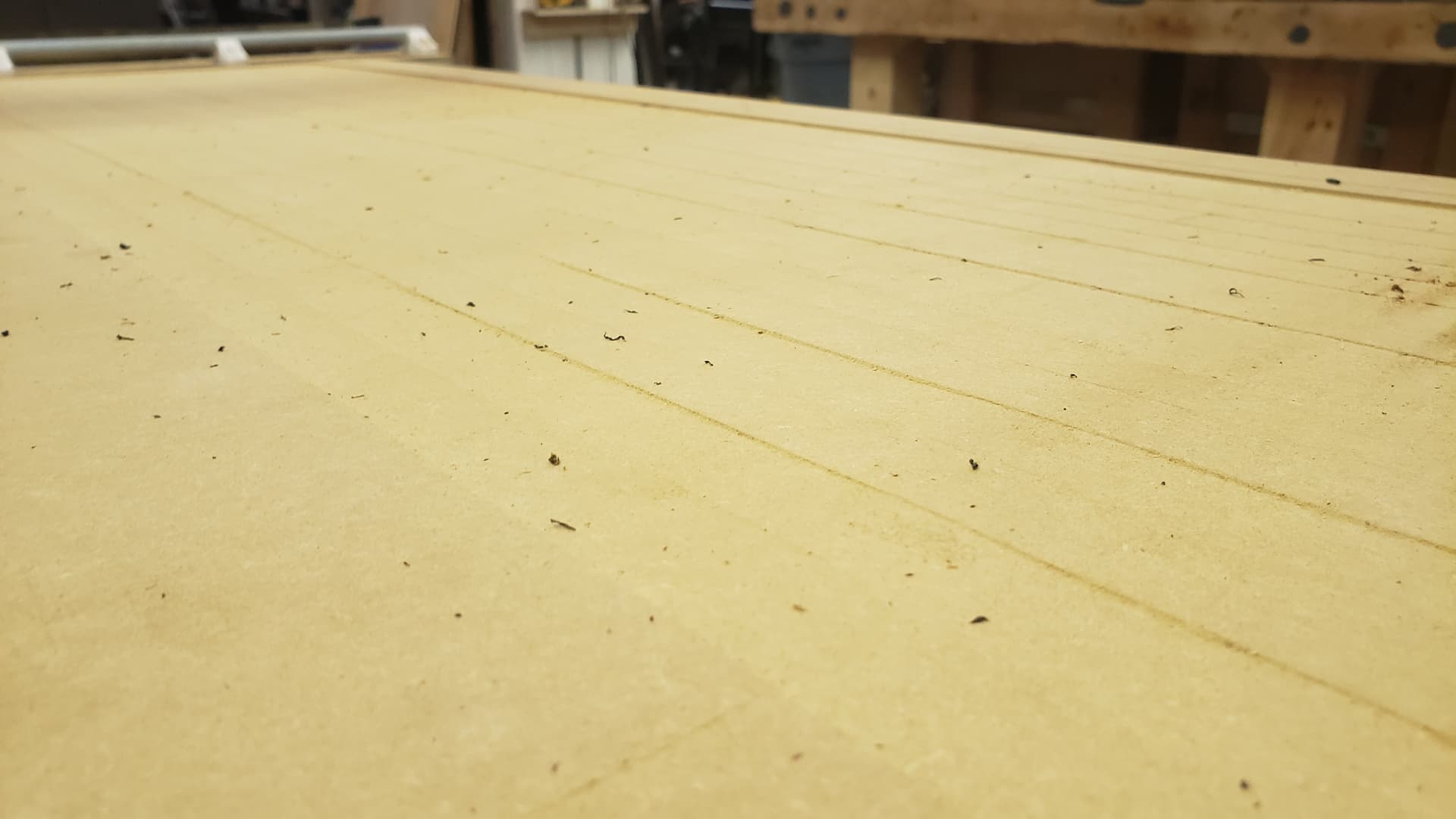
I got around to surfacing my spoilboard but only did one of two passes after seeing that my router wasn’t parallel resulting in ridges and uneven work surface
I ended up tramming the router early this morning. Used 3 washers (6 in total) on the top brace. It is still 1-2mm out at 4 inches. Is this good enough? If not is 4 washers too much?
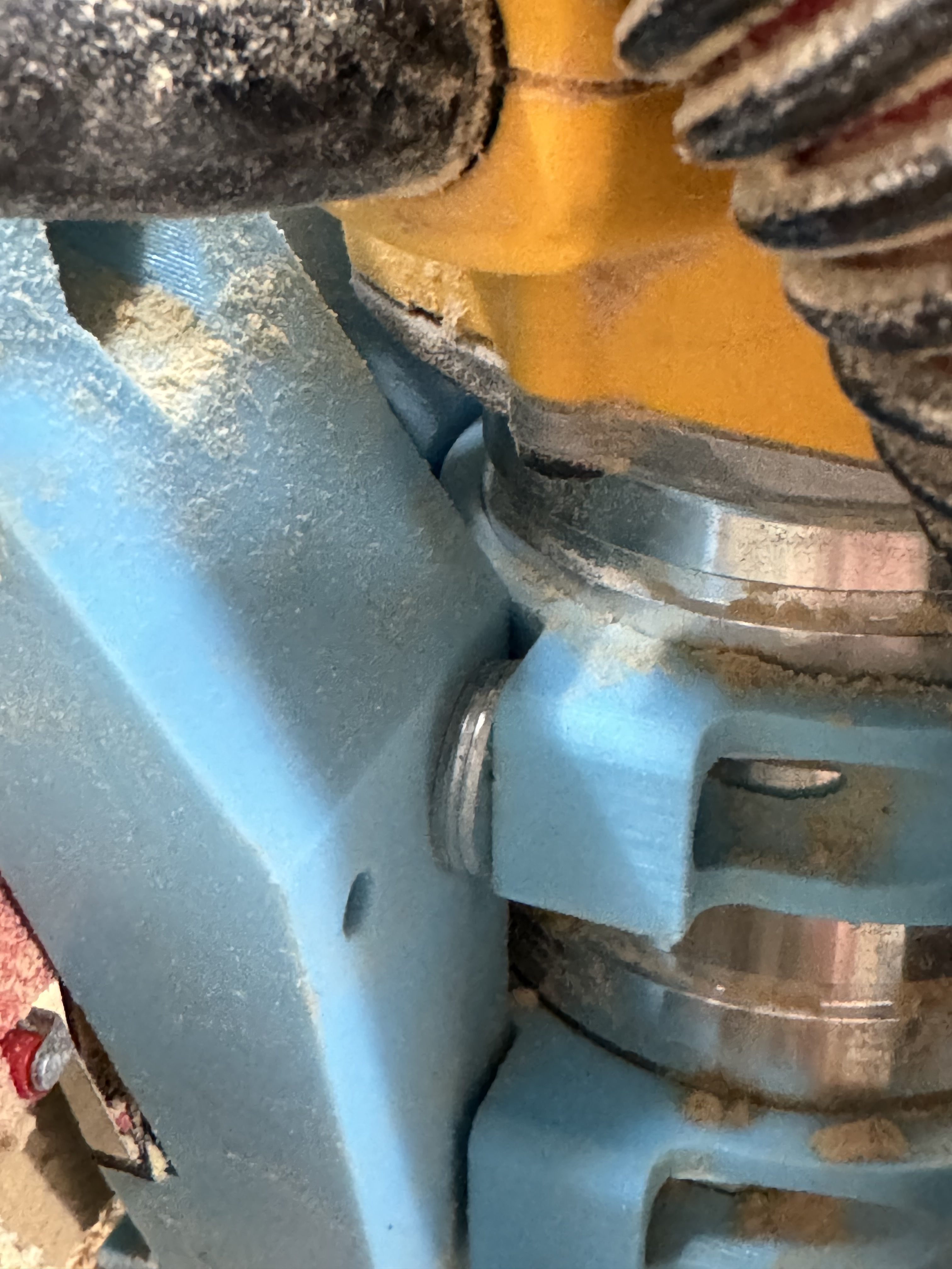
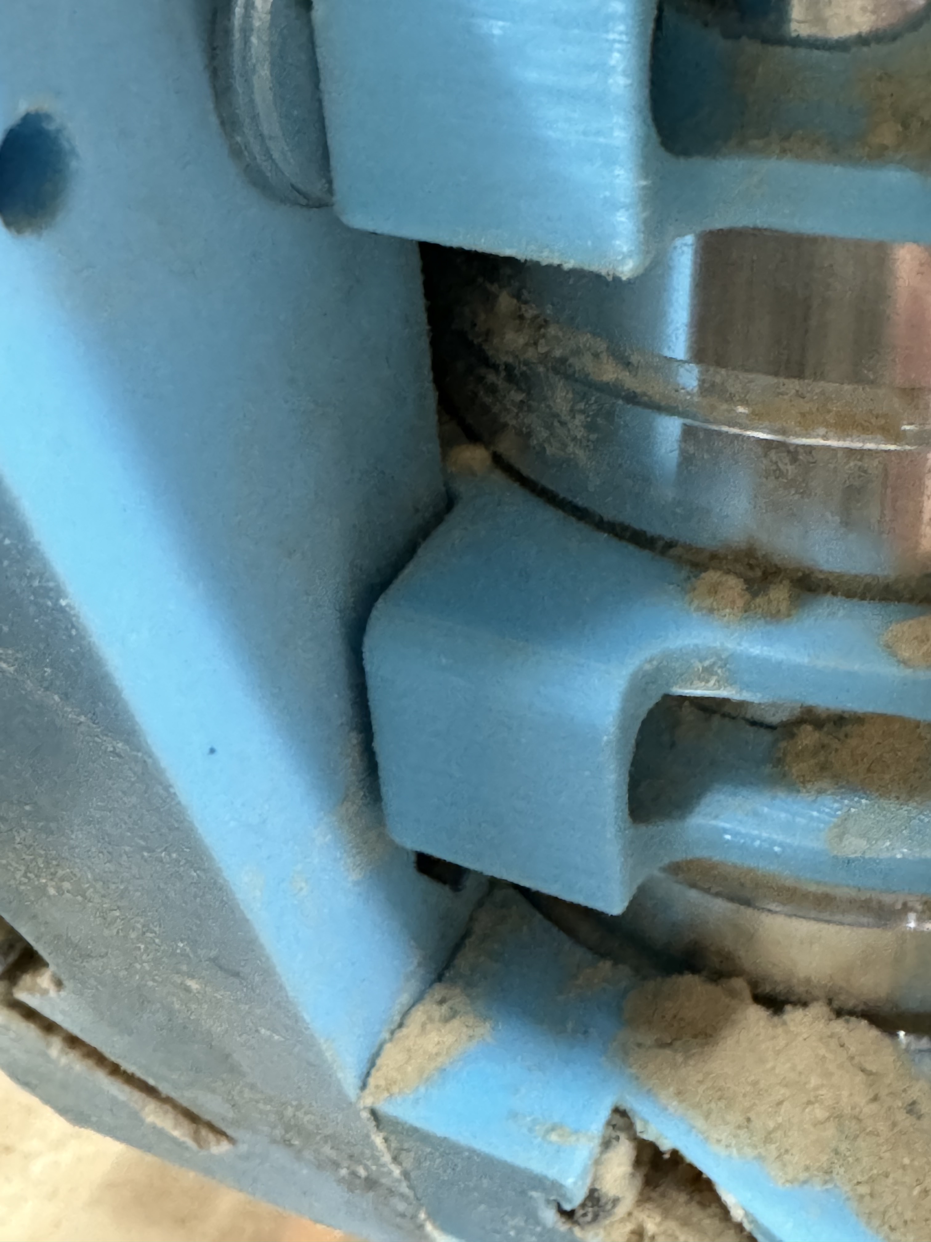
So here are the photos I could get. Washers are 1.25 mm so 3.75 mm shims
It also looks like my bottom tool mount isn’t sitting flush but the bolt is tight (snug then two rotations). It look like that gap may fix the last of the tramming. But should I tighten this?
Edit/update: apparently I fixed it??? Attached the two bits on a tram arm again and now it’s parallel? I had losened the lower mount and started retightening both sides again. Gap is still there but the issue is fixed? Do I mess with this black magic to figure out why that worked?
I’m no expert, but I’m pretty sure that the gap on the lower mount indicates a problem with the whole system.
Typically the printed parts fit together pretty tight (at least in my very limited experience), with no gaps or voids. I would look for things like elephant foot, and maybe check the printer calibration again. You may need to shave any edges or protrusions to make a better fit.
The gap wasn’t there before adding the washers to the top mount. I’ll check everything again when I get back in there in the AM. I don’t usually have calibration issues as I print a lot of precision parts but 3d printers can be unpredictable so I’ll double check
Yeah, it’s probably pivoting on the vacuum shoe, so you may not be able to close the gap with all of those washers in the top mount. Tightening the bolts too far could cause a crack.
It seems crazy that you would need to add so may shims to get the core perpendicular to the table. I’ve read elsewhere that a layer or two of tape should fix any out of perpendicular issues.
It could very well indicate a problem in another area (twisted gantry rails? loose core tension bearings? skew on the printer?) Again, I’m about as far from being an expert as you can get, but something seems off here.
Is this consistent across the whole X axis, or does it change if you move the core between XMin and XMax?
Tested this out and results are all over the board. From what I can check the frame isn’t twisted and is okay. However I also don’t think I needed the spacers……… or at least not all of them
I was testing by taking a 3d printer glass bed setting it on the spoil board. However my spoil board is so out of wack that this isn’t flat enough for this test even with the glass. Why the three spots I picked happen to be the only ones that worked idk. But after testing multiple areas it changed everywhere. I will need to remove it from the table and square on my workbench or a flat surface.
Ummm… Got a wire coat hanger and a 1/8" collet? Make yourself a quick double-90 ‘Z’ with a decent throw, and use that to test for perpendicularity. It’s a lot easier than trying to check the ends of the flutes. It’s also a lot more sensitive, since you’re exaggerating the error across the throw of the arm, rather than the diameter of the bit. Doesn’t even have to be perfectly square angles, either. Just as long as it’s consistent all the way around, it’s perpendicular. Maybe wrap some tape around the end so it fits snug in the collet.
Ryan even has a couple of tramming tools over on Printables that might be useful to at least look at. They’re for the DW660 and Makitas, but they’re designed to slip over the collet nut, so my guess is they’d likely either work with the DW611, or be easily remixed.
I didn’t realize Ryan had one. I printed two different types one that uses two 1/4 router bits and another that uses a dial indicator. I’ve only used the router bit version as my dial indicator is bigger than the 8mm.
I didn’t think about that. After retightening I twisted the router to make sure it didn’t move and it didn’t but with how the brackets are designed the top one shouldn’t be tightening. I imagine this might also introduce issues while traming
Here’s what I am going todo. I’ll get into the shop tonight, take the lr3 off the rails set it on my flat melamine workbench. check rails for twist, check the core to make sure all bearing are in contact. Power it up, relevel the z axis on a flat top (now realizing that is probably skewed as well). Tram the router in the middle of the x axis via the tape method; using the 4" tram arm I have, and using the 3d printer glass bed again (now that the surface will be 90-99% flat). Double check square/perpendicular in X Min/Max as well. Then if all checks out I’ll check back in here with my hopeful success and use Vector76’s surfacing gcode set to N (this should eliminate any tram issues altogether) vs estlcam and hopefully wont have any more issues.
man I am ready to make dust that isn’t mdf spoilboard dust
Welp good and bad news. Taking the lr3 to a flat surface worked wonderfully. Got the Z level to within 0.1mm, and the tape method worked wonderfully (4 wraps of tape did the job). However the bad news. After tramming in the middle of the x axis I have revealed a twisted gantry. At x0 it is roughly 2mm up in the back at x1200 it is roughly 2mm down in the back. What do I do to fix this? Is 2mm flex worth chasing?
Is that a twisted gantry, or are your z endstops offset by a bit (resulting in the gantry skewed in the Z direction along the X axis)?
The gantry twist (if it exists) could possibly be checked by removing the core, then placing the rails on a flat surface. If it is sitting flat on both rails the whole way, then it should be good, but if one edge is lifted at one end, then you may need to give it a twist to straighten it out.
Either way, you may need to add or remove tape afterwards.
I’ll have it apart in the morning and check the gantry.
My measurements were as follows
X0: tram in front 1.88mm away (size of touch plate)
X0: tram in back 3.1mm away
X600: tram in front 1.88mm
X600: tram in back 1.89mm away
X1200: tram in front 1.88mm
X1200: tram in back -.2mm
I feel like if it was the Z end stops I’d be seeing more divination in the left and right not front and back
Yes, I wasn’t sure by your initial description, but with this additional information, it seems like the Z endstops are set up pretty close. This assumes that you didn’t move the Z position between measurements. If you did raise the Z between moves and then reset Z0 using the touchplate before each measurement, then all bets are off.
The front to back variation along the X axis seems like twist may be a factor, or your table surface is really crooked.