Some people put a Zen in their living rooms, others just make do with a LowRider… ![]()
4 Likes
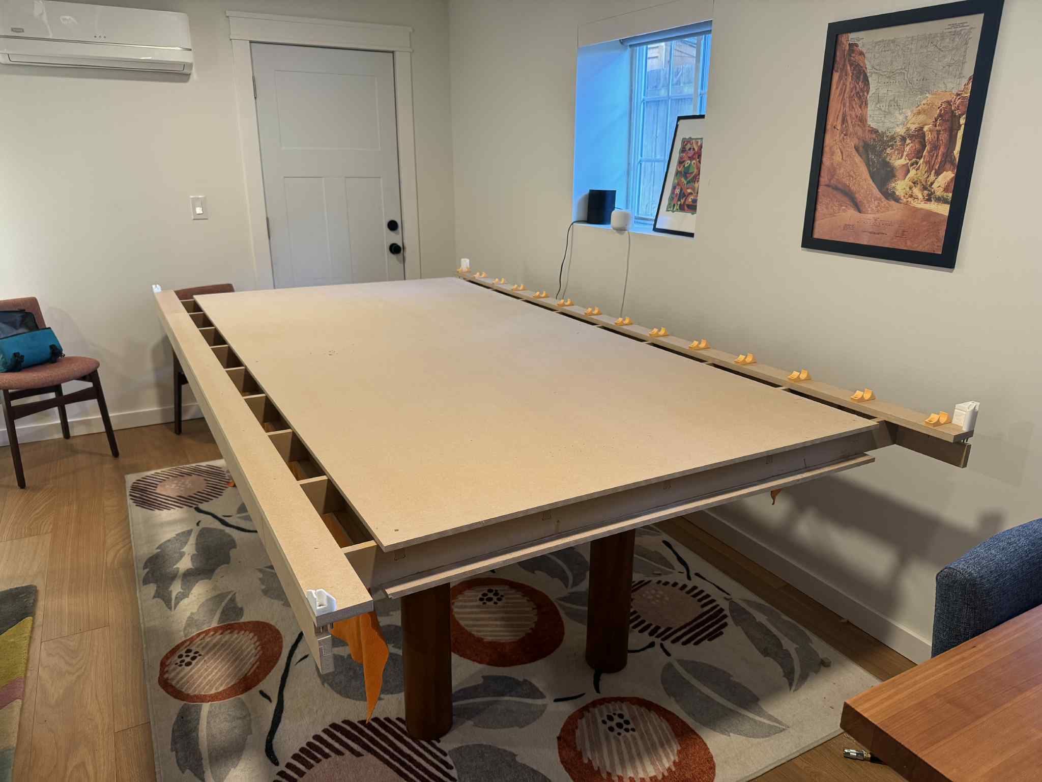
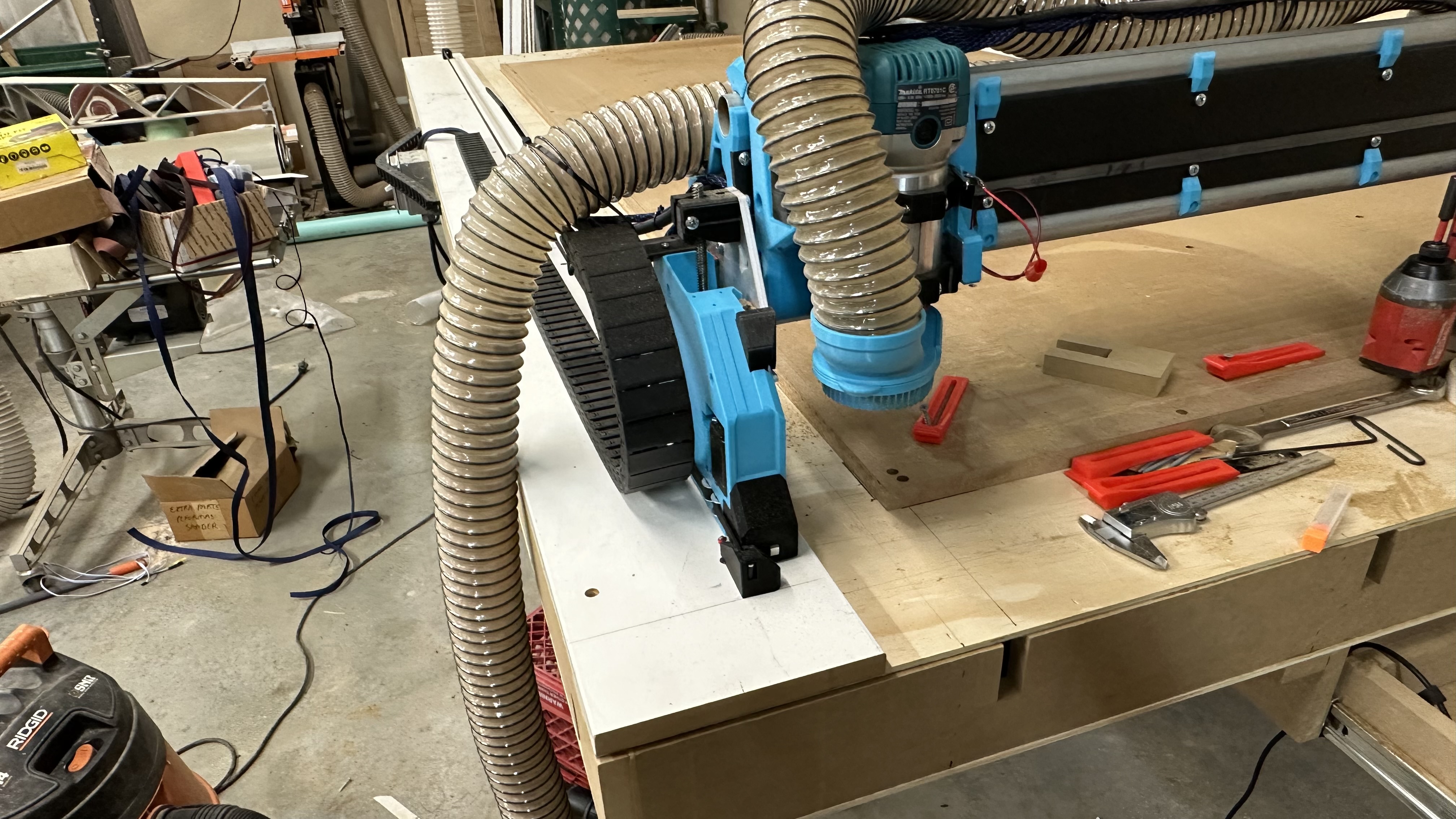
It’s all put together. The pre-drilled holes for the rail clips and bar-ends worked pretty great. I had to cut a few little notches in the spars for screw, but overall it came together nicely.
I’m marking this topic ‘answered.’ The table generator works, and the result comes together nicely. I’d love to see if anyone else tries it, and/or I’m happy to fix any bugs or issues you find!!
6 Likes
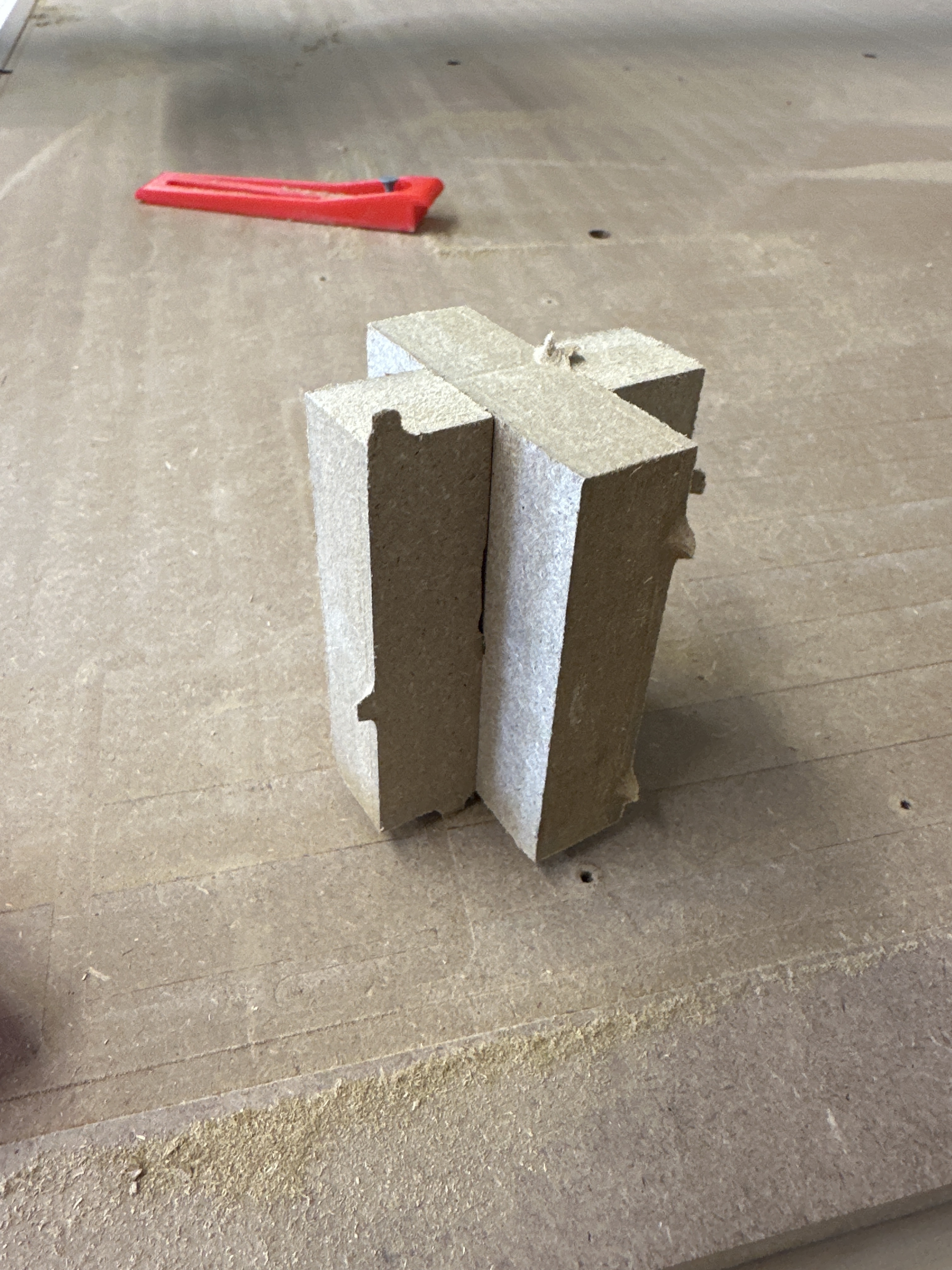
Is the gap in the lap joints exactly the material thickness?
Might be nice if we could specify a “fit tolerance” that would add a few thousandths - previous work building a table like this showed me that fitting all the pieces together becomes really difficult if there isn’t a little slop in the joints.
Started to play with the test fit pieces today but got interrupted by a failed septic tank pump. Just what I wanted on a rainy Easter Sunday…
2 Likes
I would expect the material thickness to be set to whatever value gets you the proper fit from the test pieces. I don’t see anything in the design where separating the tolerance from the material thickness would gain anything.
3 Likes
It is, and I agree with @jeyeager that you probably want to mess with the thickness first. If you have problems I am happy to explore adding a configurable extra gap.
Thanks, I’m tinkering now. Just wanted to verify that setting a thickness value that’s a little more than the actual thickness wouldn’t throw off any other part of the layout.
One thing I need to keep in mind (and pointing it out for others who may come along) is that all MDF isn’t the exact same thickness – I’ve got scraps in my shop that are .745", .755" and .760", from different brands and local suppliers.
So I’ll really need to get the material I intend to use for the actual project and test the fit in that material.
I’m definitely impressed with the generator - thanks a bunch for throwing it together!
Oh - one more thing I thought of:
Would it be possible to either change the orientation by 90 degrees or add an option to allow that? It’s a little bit obnoxious to rotate the drawing in Estlcam every time I open it… ![]()
The only other part of this that it should affect is that the side rails are included in the overall X dimension. So if you want the table to be 60" in the X dimension, it will build X spars that are 60 - (2 * material thickness). Because you clap the side rails on the side.
OMG, I was also annoyed by that and never thought to just rotate it. Yes, I can do that, it should be very easy…
2 Likes
5 Likes
Next question, regarding the side rails:
What are the lines at either end for? Alignment to the x spars maybe? Did you just use a V-bit and make a little groove for those or what?
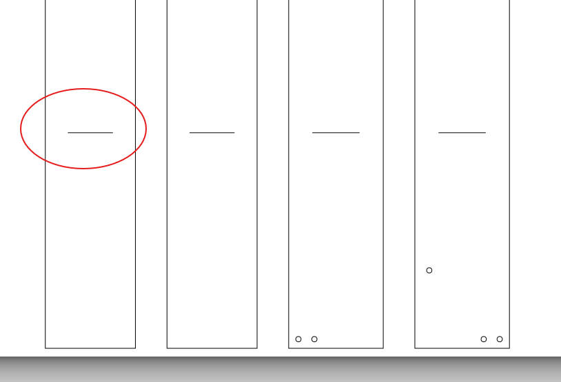
Yep, those are for aligning to the X spars. I just cut little slots with my end mill. They’re not super critical.
1 Like
As I’ve been playing with the new table and getting it square I realized that my assumption about the front and back buffers for the sidecars being equal might be wrong.
@anon32961777, I would ignore those little marks for the spars until I can get it fixed. I’d just attach the spars last if you’ve already cut them.
@vicious1, are the distances from the front/back belt clips to the cutter head constant? Do they change for the different routers?
1 Like
Thanks for the heads up. I’m going to work on getting the table cut first before I worry about the side rails.
Ryan’s non-CNC design uses different widths for the side rails. And it appears that the distance from the edge of the spoilboard to siderail is different from one side to the other.
I wonder if it would be possible to make the rail width configurable for each side? I’ll be looking to add a drag chain on the Xmin side, just outboard of the belt. On the Xmax side, I only need the side rail to be wide enough to accommodate the mounting clips for the EMT conduit track and belt. Changing those widths would change the length of the X spars to accommodate.
I don’t think that changing the width of the rails will change the length of the X-spars (since they will still have two rails clapped on the sides, and the overall width is set by:
X cut length + buffer from calculator = (2 * rail material thickness) + X-spar length
However, the rail width is currently set to have both rails be 5mm wider than the width needed for the mounting clips. I could make it match Ryan’s drawing and have the flat rail much narrower, that would be easy. I think it would be better to have that not configurable, though, because I’m trying to avoid having too many different parameters here, it’s more to explain/confuse people. Open to being disagreed with though!
You can poke around the CAD, but what you see there should be considered minimum.
2 Likes
Maybe I’m not visualizing it correctly, but…
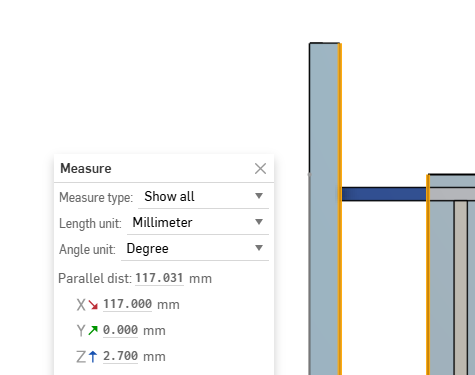
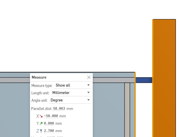
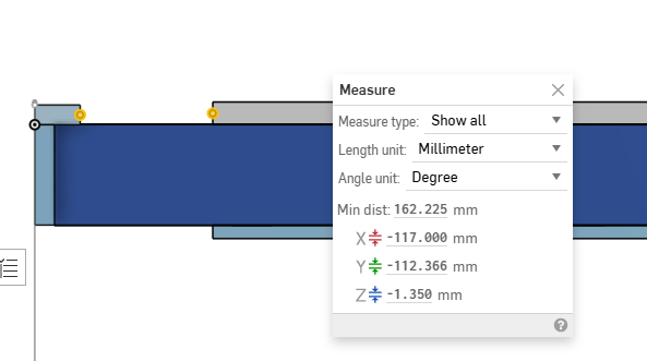
My assumption was that the gap between the table top and side rails would be constant - essentially being the distances shown in my screen grabs from my previous post.
If that’s the case, then changing the width of the side rails would require the X spar length to change as well, so that the the outer edge of the side rail would be past the end of the X spar by the thickness of the side rail, and the vertical side rail piece would attach to the ends of the X spar.
From a front view on the OnShape project for the non-CNC table:
I definitely don’t the generator to be any more complicated than necessary, but this feels like one bit folks are going to want to customize. I’ll likely end up modifying the X spar widths from the generator to allow for wider side rails if the generator doesn’t handle it for me - not really a big deal either way, I guess.
Sorry, I’m a little confused what you want for your project.
So, you want the drag chain to rest on top of the top rail, alongside the belt?
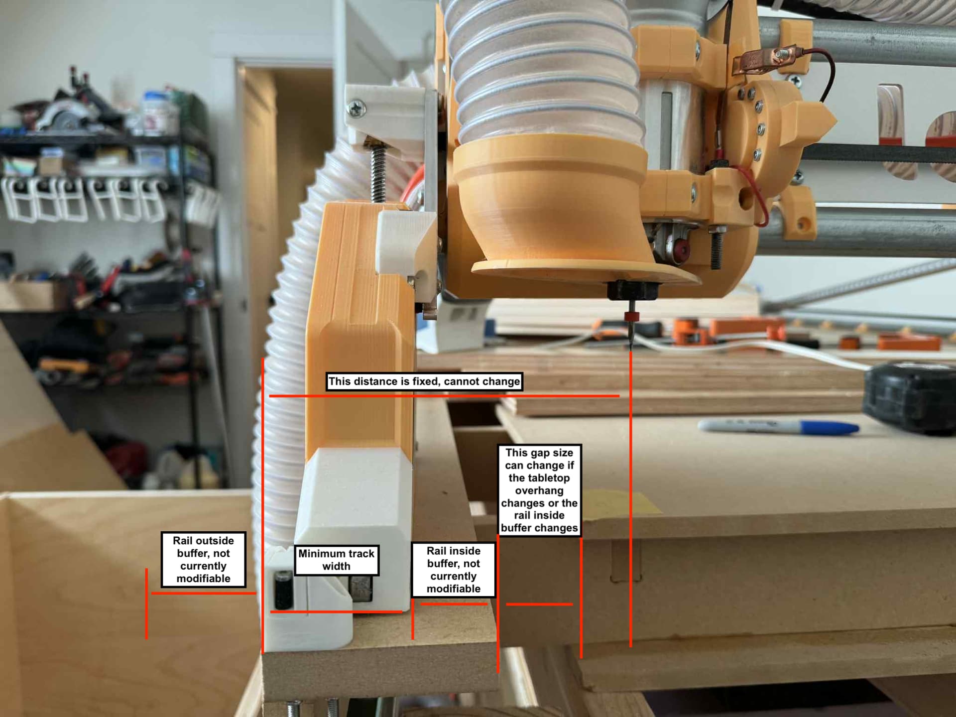
I think to be precise the distance that is fixed is the outside of the belt stand to the cutterhead. This distance is made up of, in order, the belt stand fin thingy, the belt, the YZ cart, and the side of the core.
So what I think I could add to help you here is modifiable inside/outside buffers for each rail. I also probably need to slightly modify the grid positions in the X-spars to reflect the fact that the core is asymmetrical, will try to get to it tonight.
3 Likes
And to be clear, there is currently a bug in my table design, which is that the tabletop shouldn’t actually be centered on the X axis. You can lay the spoilboard wherever, but ideally there will be supporting y-spars all along the inside edges of the spoilboard. So, I will try to fix that part tonight at least.
1 Like
Yeah, I run power lines, etc. in a drag chain
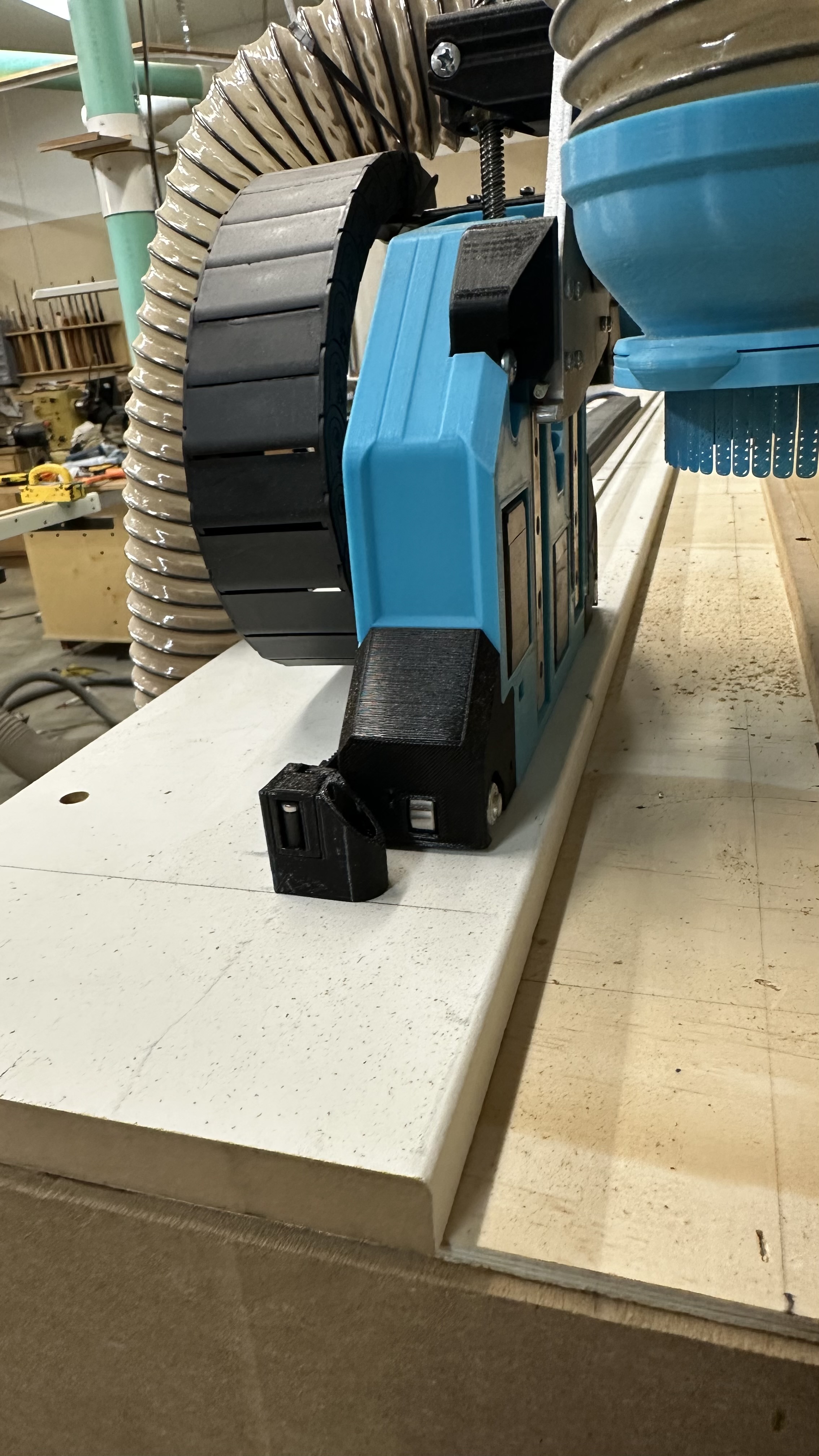
That would probably work. I’ll note that the buffer on the inside is largely unnecessary - you really need just enough for the “wheels” to run on.
Ideally, zero on the x axis would be exactly at the edge of the table top / spoil board - that’s the only way to get a fully-supported surface for doing full MDF sheet cutting on. But I also think there’s going to be just a little bit of variability in where that zero actually ends up, owing to how the x axis is assembled, where the limit switches trigger, etc.
Appreciate whatever you can do - if it ends up looking like my requirements are an outlier, I can always fork your repo and change the code for my specific case (though I can’t express how much I dislike React… ![]() )
)
1 Like