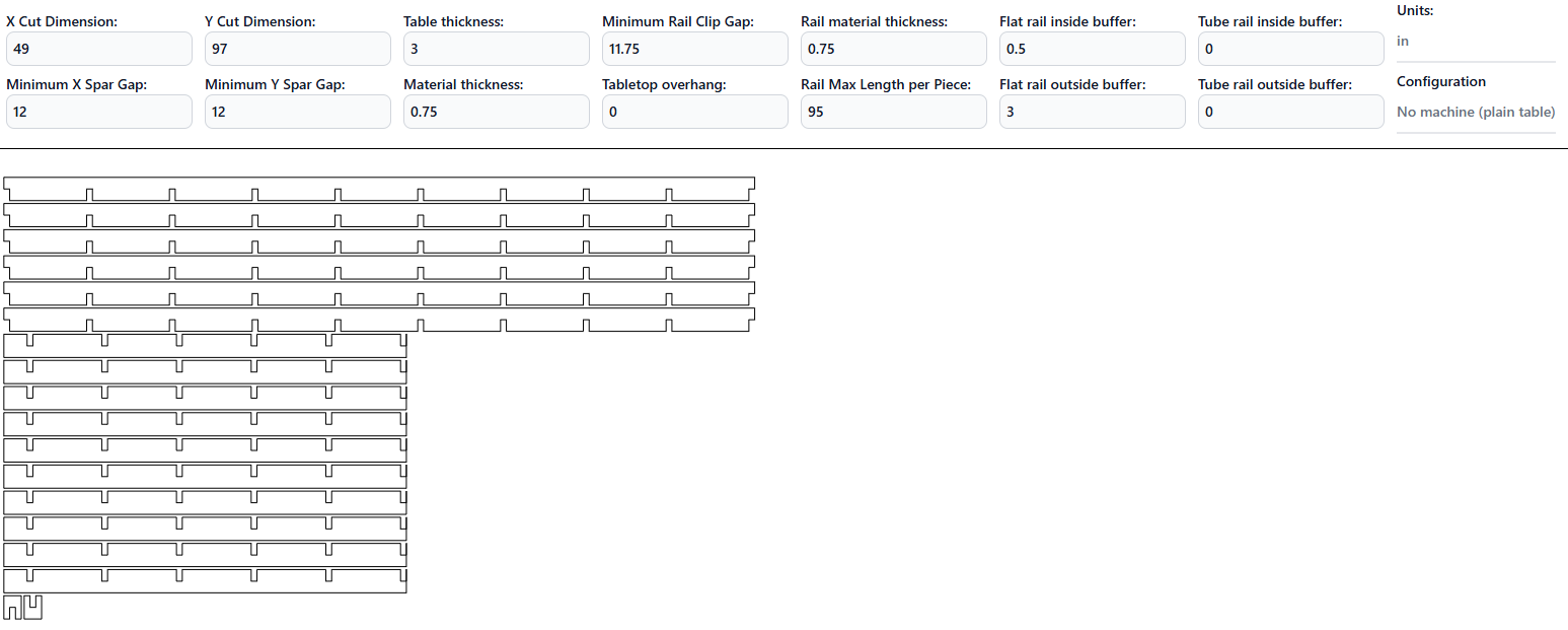
The table grid is readjusted based on the CNC drawings. The cut surface is slightly offset
You can specify custom inside and outside padding on each rail. Outside padding will increase the x-spar length.
There are sane defaults when you first launch the page.
The rotation thing is a little more annoying than I first thought, so I’m going to punt on it for a sec, because I want to get some other projects working. I’ve been informed that if I don’t get the workshop a little more organized, I will be in hot water at home…
Let me know if you spot anything odd. Thanks for trying this out!!
I notice a strange drawing artifact when I change the outside buffer values to anything other than zero:
The drill holes for the belt clips are distorted.
Will play with it when I have a bit more time, but I think this is really close to what I was hoping for.
Appreciate you working on it – and good luck with the workshop organization; I’ve been trying to get mine reorganized for about 2 months and always seem to lose focus about 30 minutes into any given session…
Can you help me understand the measurements for the rails in relation to the cut area please? Looking at your picture I see you labeled the distance from the bit to the outside of the rail as fixed. What is that distance on both the Xmin and Xmax sides? Also, what is the distance the rail has to extend beyond the cut area in the Ymin direction. I have a cutting surface that is 32" X 52". I am trying to figure out how wide to make the rails on each side and how far to extend the rails in front for a new LR4.
Yeah, I’ll admit I don’t check that setup very much. I’ll take a look later today or tomorrow. I should really write some tests or something… bleh, feels too much like real work.
I can try but my understanding is incomplete so apologies in advance if I get things wrong. My first version of the table generator (the one I used for my own table) assumed that the cut area was centered in the x/y directions, which I have realized is incorrect. This is now corrected in the X direction but not Y.
I measured on my machine (and double checked using Ryan’s model of his table). This is about 157mm on the flat side and 133mm on the tube side. I would bet that things like router choice, XZ plate thickness, and other small construction changes can vary this, so give yourself a buffer.
I don’t have this yet, but you could look at Ryan’s model to estimate it.
Are you using this table generator or designing your own? If you’re just assembling your own then I would just slide pieces around before fixing them in place. If you’re using the generator, a lot of this is already handled for you.
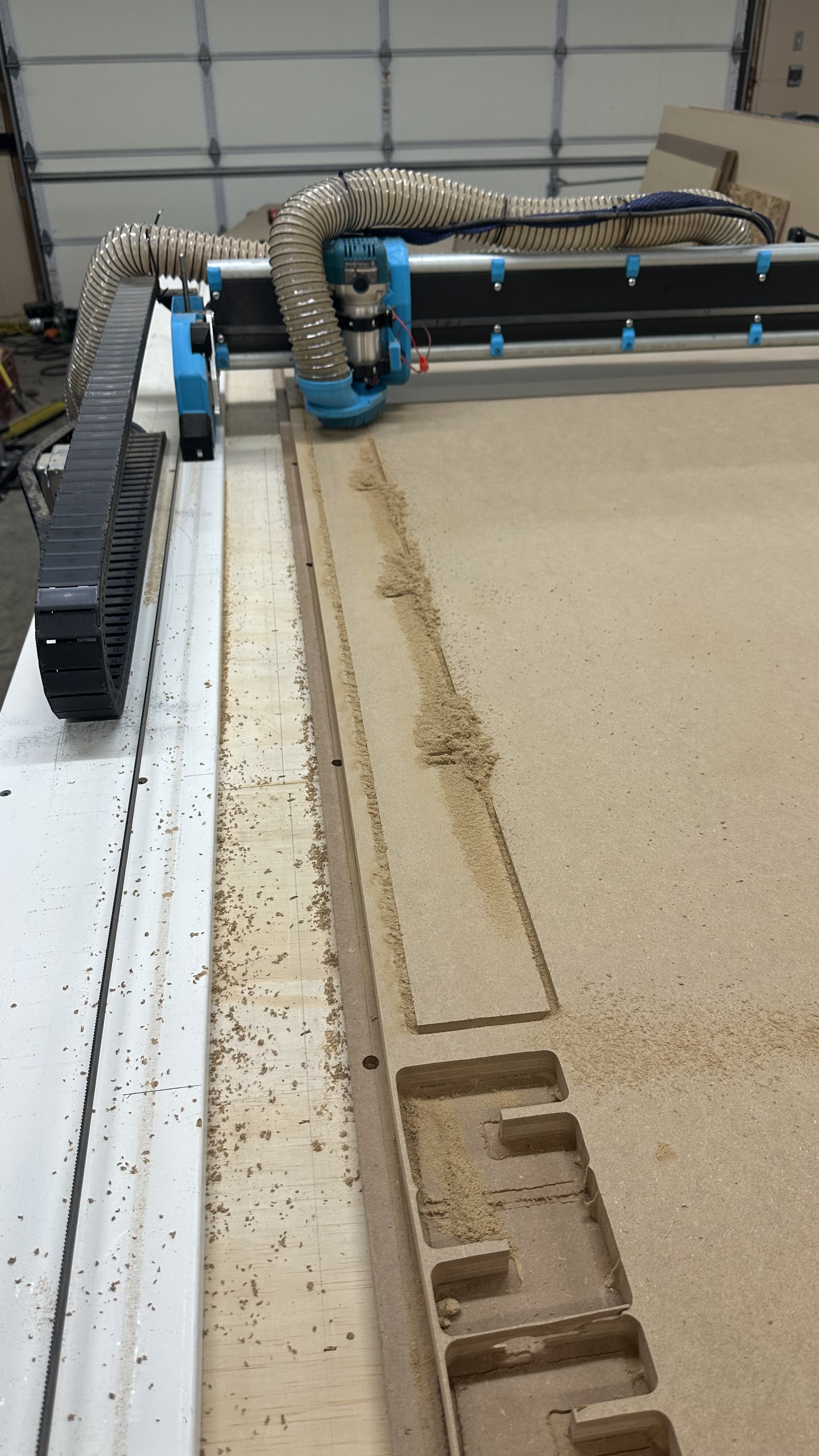
1/4" up-down compression bit, .25" pass depth, 250 in/min in Estlcam (though I’m not positive the LR4 is getting quite that much speed but it’s moving right along…) Makita router is on about speed 5 which may be a bit too high but sounds better than listening to it bog on lower speeds.
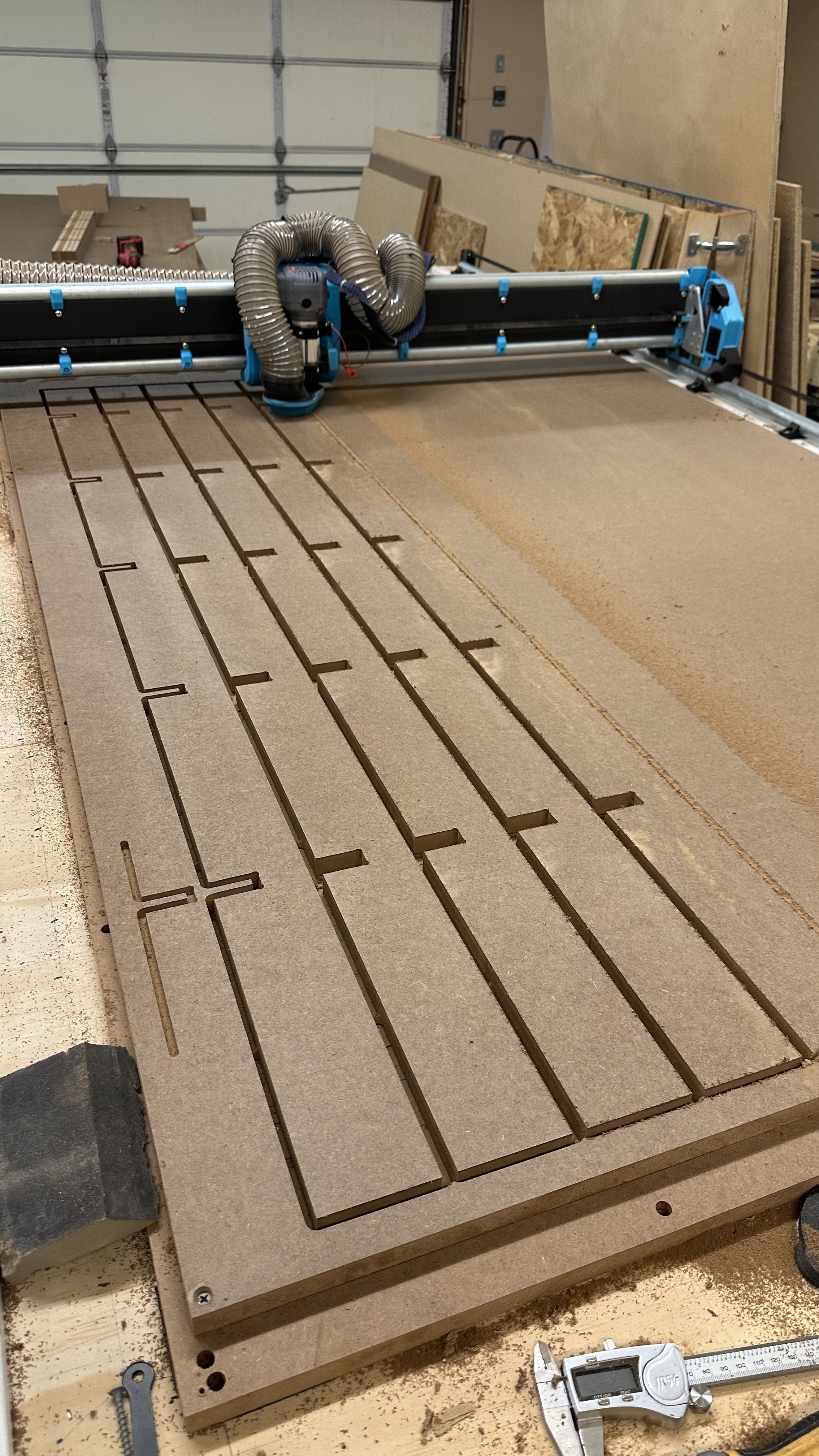
Discovered about 2/3 way through the X spar cuts that I had some wobble on the x rails - enough that I could watch the whole core move in the Y axis direction as the notch cuts were being made. Result was a bunch of pieces with a way-too-narrow notch, so those will get donated to the scrap pile and I’ll start again now that I’ve tightened the rollers to alleviate the wobble. If I only end up scrapping 1 sheet of MDF in this process, I’ll still be happy…
The only other customization I can think of that might be helpful would be to allow setting the spacing between parts - I had to spread them out a bit in Inkscape so I could leave enough “meat” between the parts for the tabs to have something to attach to.
Oh, I just put the tabs on the same place, so that parts were connected by tabs. But increasing the kerf should be pretty doable. I’ll take a look later.
I have tried inches and mm, online converters, and re-exporting through inkscape. No matter what I do I can not get this to be scaled correctly in Aspire v12. Could this output a DXF format or include reference dimensions so I can manually scale the import?
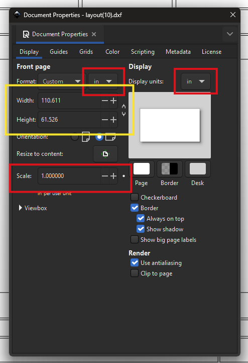
I set the scale to 1 DPI, and the format/display units to inches (if you’re entering measurements in mm on the web tool, try mm.). That’s all the red boxes.
You should see dimensions in the yellow box that make rough sense with the layout you’re seeing. Probably the width is the value that makes the most sense to check directly. This will be just slightly longer than you expect the Y dimension of your table to be.
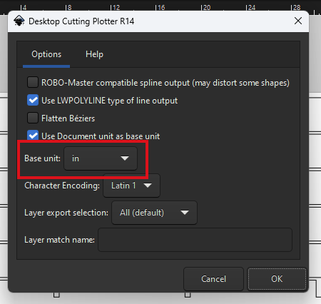
Now, save as a DXF. File > Save As, pick DXF14 in the filetype dropdown. You should hopefully see a window like this where you can pick ‘in’ (or, I guess, mm if that’s what you’re working with) as the unit.
This will create a DXF file. When I import this into Vectric (I just downloaded the free trial myself, hopefully your experience is the same/similar…) I see everything at the correct dimensions.
I think this process will help me with other SVG imports into Aspire. Some search terms to help others find this information: SVG scaling, SVG import, SVG too small, SVG Aspire, SVG Vectric.
Maybe you could post this independently as a software tip. I would be happy to do it, but I don’t want to take credit for your solution.