Time to see how bad I can mess this up

After poking around here a bit, I finally clicked print. I even got the Mrs on board with the build and the need for it. Core only took 10.5 hours. So carry the 1 and divide by 0, should be done printing around this time 2025. LOL

Here’s to getting this project started.

9 Likes

I think my first step is going to be upgrading the printer to flow more. I have a rapido hot end sitting in its box. I think putting it on my E5s1 would save me gobs of time printing these big parts. I need to wait for more filament to get here anyway, so printing off little 3D printer parts in the mean time is probably time well spent.

Phaetus-Brochure-2-pdf

as it stands, my printer can reliably flow roughly 20-25 cubes. The Rapido UHF claims to do up to 75 but I have seen 45ish reliably. That’s almost 6 times the plastic being printed per second. And because I’ll actually need to slow my speed down to get the flow rate and cooling correct, it should give me much nicer prints much faster.

3 Likes

Let us know how the new hot end works out! I have a Rapido HF hot end here as well slated to go on my Ender 5 Pro Zero G upgrade. Still have to print the parts for that LOL

1 Like

I am currently working on designing a mount for it. The Ender 5 S1 is just different enough from the other 5’s that almost nothing works.

Starting from here and working my out to the fan.

1 Like

I need to do the same thing for this H2 V2S Lite on my MP3DP V4. Right now I’m setting it up without part cooling since the first thing I’m printing is ASA parts for the Zero G conversion on my Ender 5 Plus lol.

My LR core took 37 hours to print… I envy you so much right now.

I tried to switch my Snapmaker A350T from the default 0.4mm over to a 1.0mm hot end and I ended up almost destroying my entire 3DP module… sometimes i wish I’d gone with a different make, everything is so proprietary with SM…

1 Like

to be fair, it called for just over 14 after slicing. But according to kilpper it was just over 10 hours. I would have to pull it up to see exactly, but it ahead of schedule.

I’m trying to decide on size based on needs and available resources including space.

so I’m going to back WAY up to before I got trapped in this giant rabbit hole.

I am an EE by schooling, a mechanic by trade, and a guy who buys more tools just so he can learn how to use them by birth. I have a 24x24 garage shop that would be good size for anyone doing any one of the things I do. BUT I do lots of things that all need that sort of space.

That is the most recent iteration of my mechanic tool section. Its about to get reworked so my air compressor is outside giving me more room on that end of my tool box for my welder, creepers, jack stands etc.

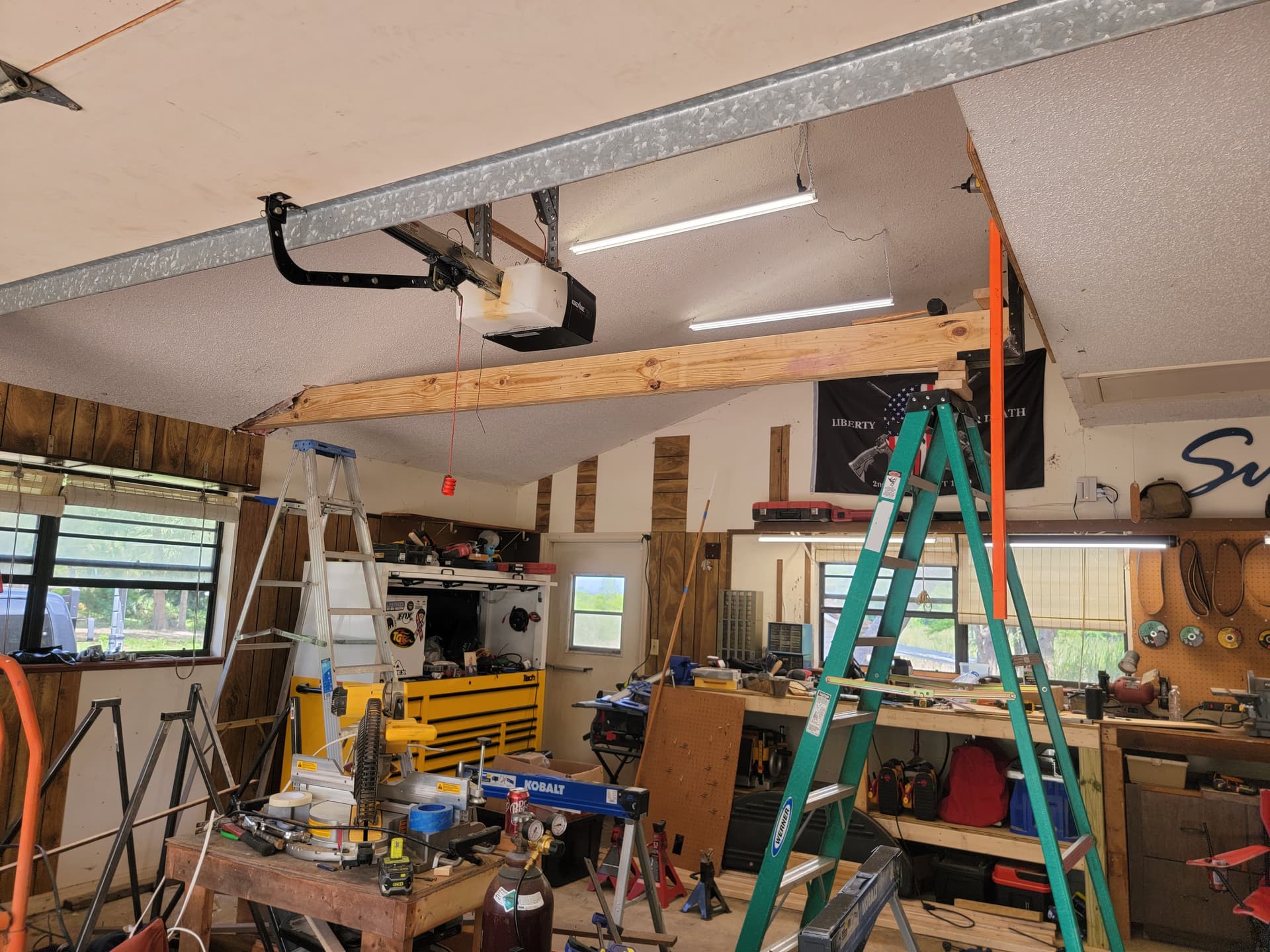
on the opposite wall is my Miter saw station which is more of a “woodworking” station. The yellow thing hanging in the top right of the picture is the control for my electric hoist/gantry crane seen bellow

and the back wall is my hot work type stuff. Metal fabrication tools, knife making tools, welder stuff… things that get hot.

not bad yet because the most I give up from any one wall is about 32" BUTTTTTTTT


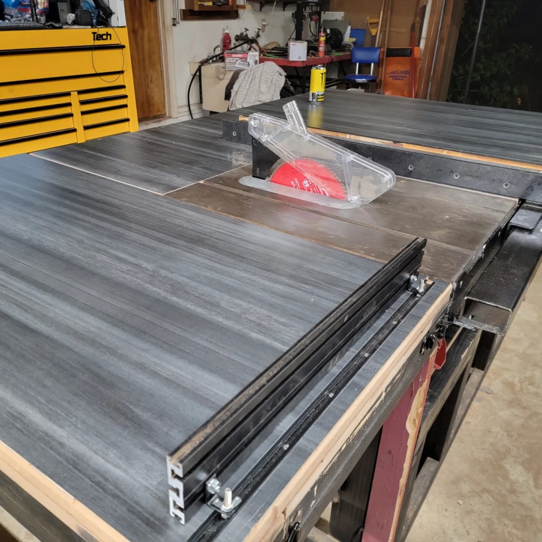
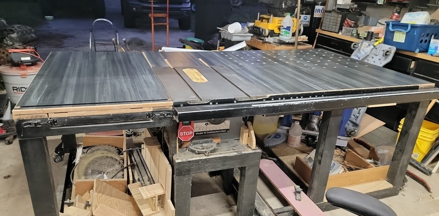
this is my 4’x8" assembly table. It also holds my table saw and has a sliding cross cut cled. She is BIG. She is also on wheels so I can move her around for differnet shop configurations.

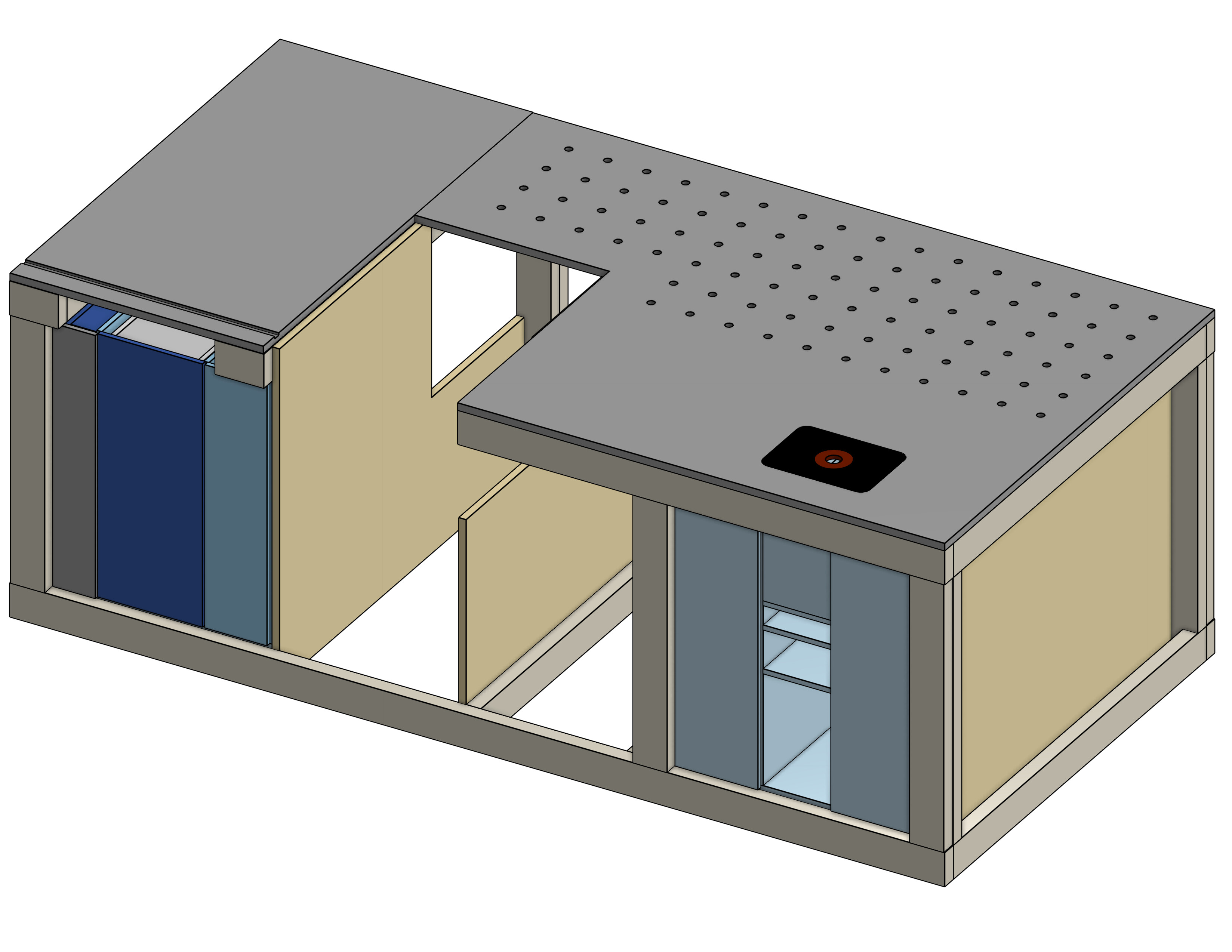
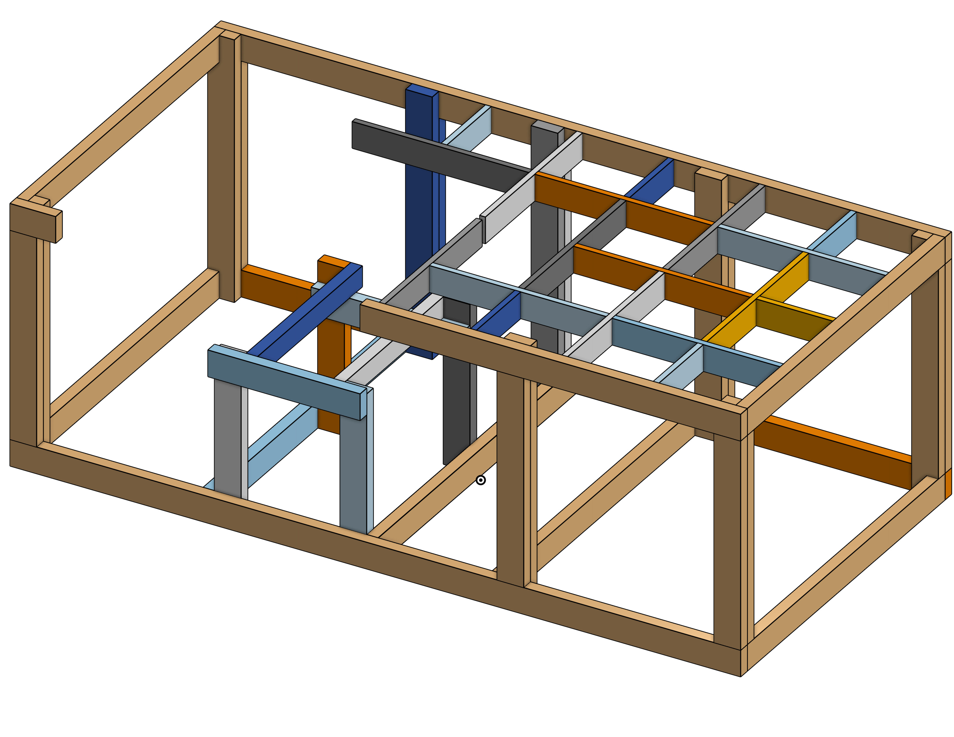
Now here is my working thought process. Hidden belt mod like Doug has done. But make it “floating” around my assembly table to allow for cutting a full sheet of MDF. But also make it removable so that I can still use my crosscut slide.

Once I have the LR3 opperational I can get a better feel for work flow. But I almost never have one project on the go at one time. I dont know even know what that is like. I always have very many multiple at various points waiting for different things. So being able to quickly take the LR off the bench and have the full bench is important. It also has to be easy to go right back on and still be one homing opperation from being back in calibration.

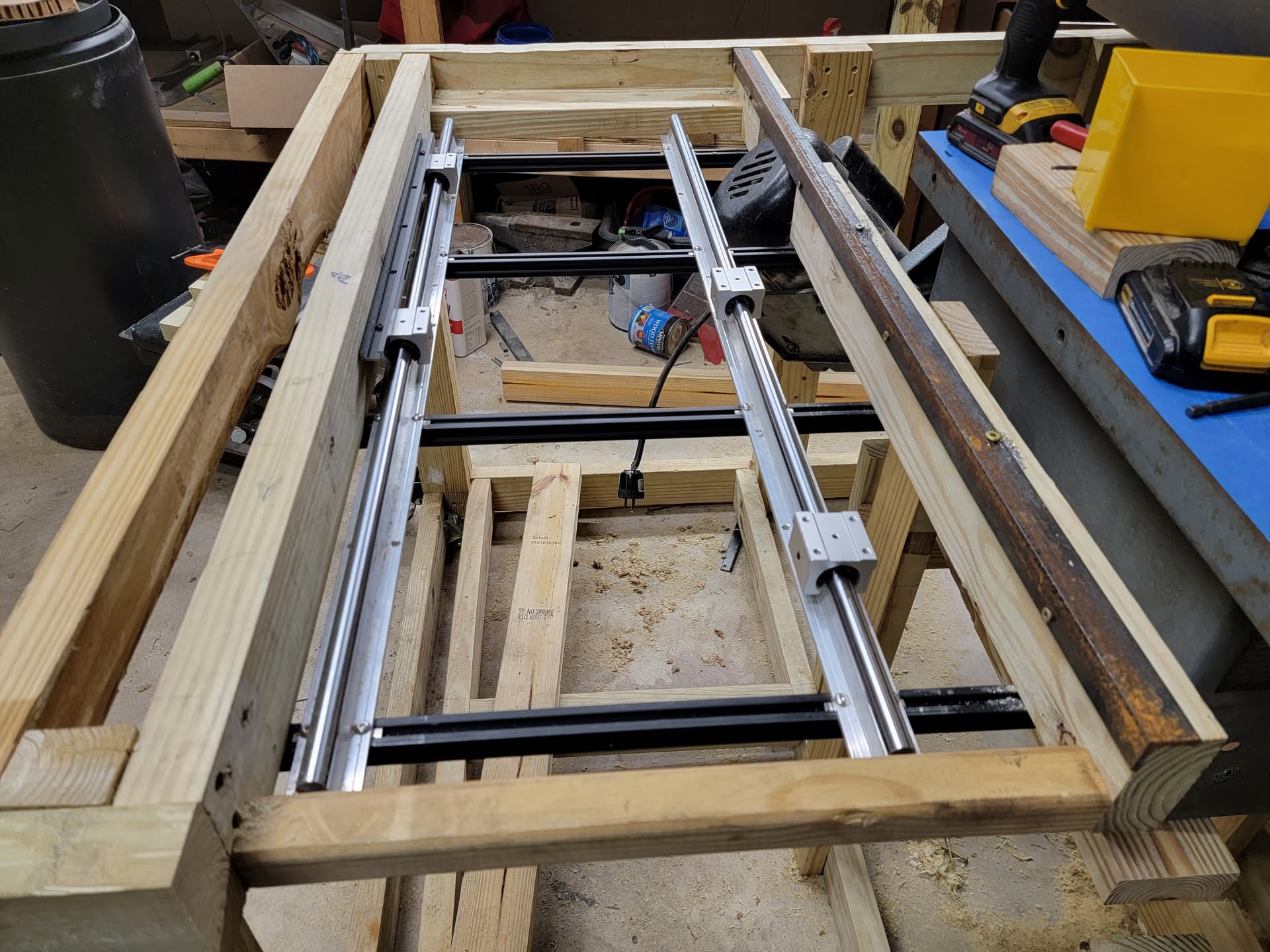
One thought I had was to take advantage of my table saw fence guide. If you look at the last picture of my bench/saw that is roughly 6feet of 2"x3" steel box tube. I could put a second one the opposite side and have dead flat rails for the LR to reference. I wouldnt get a full 8’ of Y but I could always just move the piece after the first 4-6 feet and cut the rest.

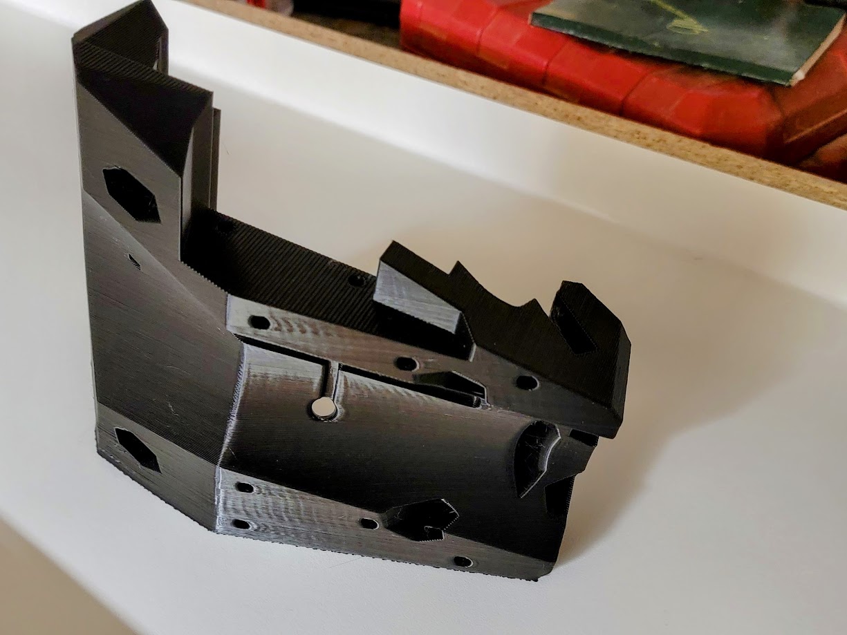
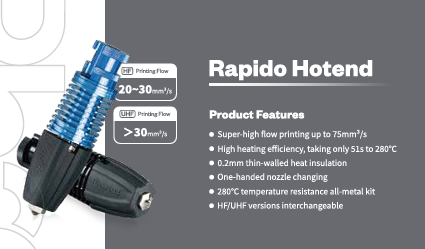
Lots of things to consider moving forward. But I know I need these printed parts, and since the mailman didnt bring PLA today, I will keep working on the Rapido Hot end swap for now.

5 Likes

I like the sound of this plan! And your setup!

Did you design the wall mounted plywood paint can holder?

I wish. They are so very sexy. My buddy Chris makes them. They are laser cut and need no glue. check out the video for info and where to buy them if you want. No affiliation or anything, just my buddy’s one man shop.

if you skip to 4:20 those are the ones i got.

6 Likes

Im glad you said that. I am going be bugging you to help me get it working correctly.

2 Likes

so, expanding on the steel rails idea a bit. I do a bunch of thinking while I’m driving and this is in the forefront of my project brain right now.

The box tube wont allow access from inside to use the hidden belt method. And I dont know of any unistrut in that size. So I need to figure that part out. The way my table saw fence works is that it clamps onto the vertical sides creating a dead 90 degree clamp. It has screws on the inside part to micro adjust the left to right so that stays at 90 every single time. Now the clamping force is just a cam lock by a lever, so its not a crushing force by any means and I couldnt see it being too much for a unitstrut to hold even after millions of times locking the lever down. But I would need the opening to be on the top or he bottom so that the table saw fance has two flat sides to reference. The LR3 will need a flat side as well so that means I would need the open side of the unistrut to be on the bottom. Not a huge deal, I will just need to design the mounts Doug used to not only reach in to the strut but also come back up. ORRRR I would have to make a trolley of sorts that stays in the channel and that the LR3 attaches to. Huge advantage of the unistrut/trolley idea is that I can have a set of bearings and wheels on the trolley so it always stays firmly in plane with the strut. Downside being that I dont know how well a printed part would hold the weight of the LR3 over time in that sort of set up. Very likely that I would need a printed part for initial assembly then use the LR3 to cut our aluminum plates to replace the printed ones.

Other thoughts about using my assembly table…

that was one of the first itterations of my table. But the point is that its a torsion box for most of it. Its not a full on torsion box with skin on top and bottom, more of just the frame with a substantial top. But for my purposes it holds the level without deviation.

My table already has dog holes on the quazi torsion side as well. So I’m thinking that I could add a few more and use them to hold a sacrificial spoil board. It could be as simple as a 1/4" mdf. It wouldn’t have to hold plane, just keep my cuts off the surface of my table surface (and table saw) while the table holds the level plane. Anyone who hasn’t used dog holes, they have various clamps and hold downs for both the horizontal and vertical plane. And with them being a set X and Y they can even be used to reference square. Mine aren’t perfect because as you can see from the picture, I did them by hand. But I could use the LR3 to make a new top for the bench with more holes in more precise locations after everything is up and running. And if the Z axis is too short for that, I just need to get the holes started and I can finish them off by hand.

Soooooo much thinking and trying to make sense of a system I have never used. I know two guys on this forum are in my general area, but I think they are both MPCNC types not LR types. If anyone is between Ocala and Tampa with a LR, hit me up so I can come see your set up and see what I am actually dealing with.

1 Like

Can someone please explain how a concrete hearth is part of building a cnc? My wife swears it is but i fail to see her logic

2 Likes

Sounds like the classic wife hack. “Since your buying that I get to buy this” lol

1 Like

If you keep your wife happy, she is much more likely to tolerate being ignored when you disappear for 10 hours on your CNC project. So yes, definitely part of the process!

2 Likes

How else are you going to get the fancy molds for the facing of the hearth? Any yahoo can make a flat-faced slab’o’crete. But with a CNC, you can make art.

2 Likes

doing some research on different version of PLA… I dont think the names of any of these mean anything anymore. these are all pla of some sort and even from the same manufacturer

Tensile Strength(MPa) 42 60 57.64 32.2 64.94 40.74 52
Elongation at Break(%) 50 20 21.76 68.9 8.64 76.85 14.4
Flexural Strength(MPa) 59.95 74 78.7 41.31 74.45 61.62 65
Flexural Modulus(MPa) 2878.5 1973 2800.36 1701 2615.14 2570.75 1447
IZOD Impact Strength(kJ/㎡) 6.2 6 6.45 8.58 8.64

So the real question is what would be the preferred type for these builds from strictly the stats listed.

Printing out the XZ plate and I have to say… Ryan I could kiss you for these designs. Everything just prints straight out of the box. I had to make a new settings preset for this project because I never print like this, but now that I have its load, slice, print, repeat

3 Likes


And it is so pretty to watch

4 Likes