This is funny. I ran into this last night right before i went to bed and decided i’d figure it out in the morning… And here’s the answer. lol…
1 Like
wasnt sure where to ask, so i figured here was as good as any
in 3D printing, we have calibration and optimization prints, like the Benchy or the Cube.
Anything like that readily available for ‘speeds and feeds’ or squareness (circles, arcs etc)for a cnc? I know i could make a file with different tool-paths and change the speeds etc, but was curious if there is already a standardized file that could be used to compare between different machines of the same type
thanks!
2 Likes
I don’t think it is that complicated with CNC. Just cut the largest square possible and measure the diagonals, with a circle you can cut and inside diameter and an outside diameter and see what combination allows for free movement.
Each material will give different accuracy and precision numbers, because of the loading.
2 Likes
yeah, after i thought about it more, the squaring calibration issues are pretty easy to do
what about speeds and feeds? do people just make some quick designs in CAD, then make toolpaths with different feeds, starting slow and ramping up per ‘round’? that way they can build a database of preferred speeds with each bit in each material?
Yes, exactly. Test cuts.
All CNC machines work that way. Bits come with a suggested set of parameters and you test to see what your machine can handle and hold the tolerances YOU need. Some people insist on 0.05mm and some are fine with 3.5mm.
3 Likes
Very nice. I’ll be happy when I figure out what is up with my motors or board so that I can do the crown. I have already made the file in preparation! Hoping it is soon operational!
3 Likes
Have you started your own thread in the “LR3 Builds” category? if you post some details on your situation there is probably some helps that can come.
2 Likes
make sure to add the starting G92 X0Y0Z0 to the gcode. just open the gcode as a text file and type it. or download ryans crown gcode and compare the starting section
it isnt in the instructions
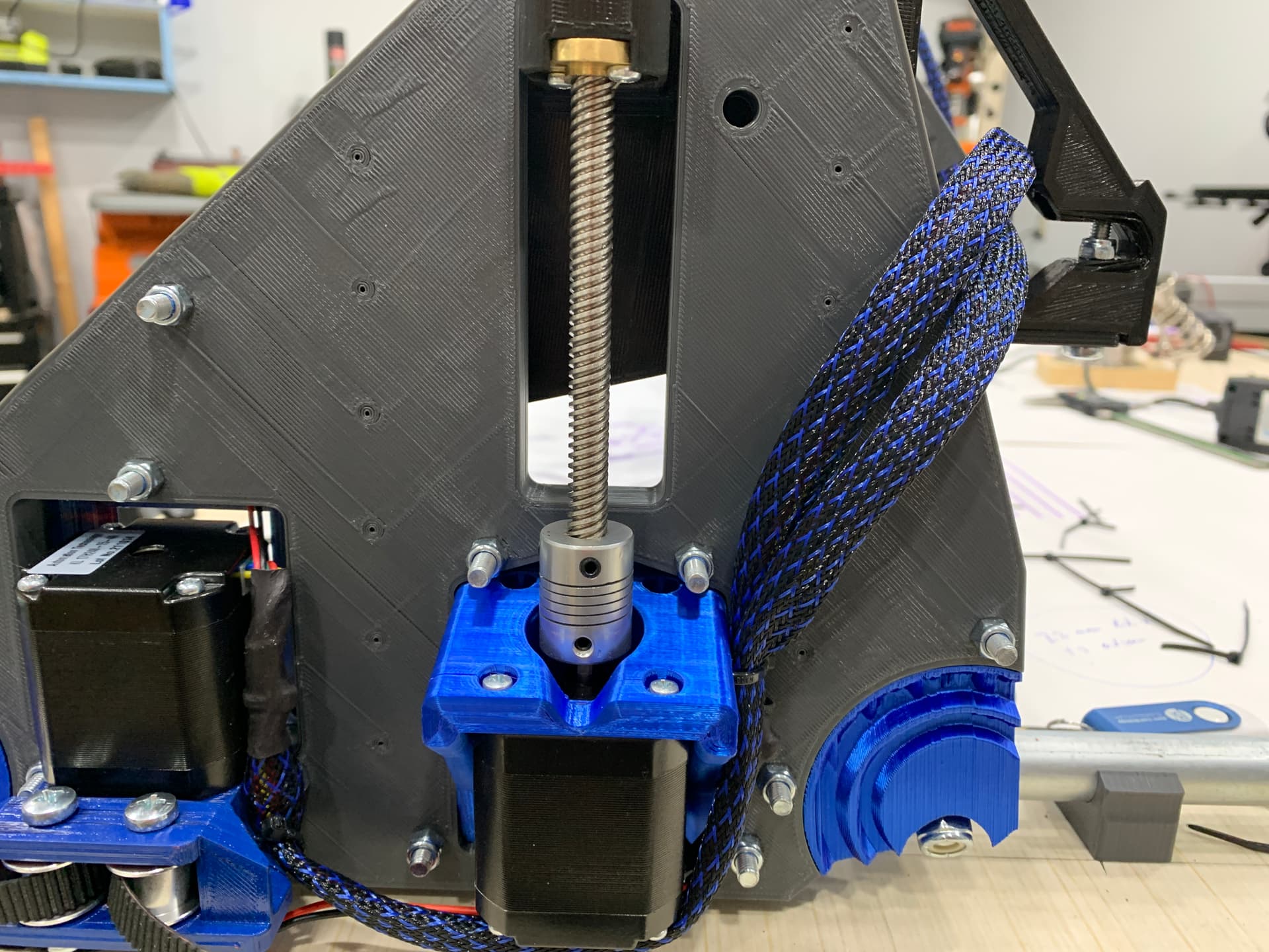
Got to tidying up the wiring with the cord sheath. man- those extensions are about 4 feet too long, lol. will need to coil and wrap them with ties and stick them in the gantry frame.
need to figure out my solution for securing it in the box- may end up drilling a couple holes next to the big V1 logo shaped hole and using zipties. i found the biggest cord gland i could in my supply box but couldnt pass the connectors through
also- using regular electrical tape to secure the connectors- that ok? i couldnt find my kapton tape and ddint want to wait for amazon order. i hate moving house
when cutting the strut plates-
Ive loaded up the model into ESTLcam, then done hole toolpaths on the internal shapes and the screw keyholes, then a part toolpath on the perimeter, using 12 evenly spaced 25mm tabs at 3mm height.
1000mm strut comes out at 45 minutes. My feed XY rate is 15mm/sec (900mm/min) with a 1mm DOC per pass.
Sound about right?
edit: did a 2mm depth of cut and 3.3mm final depth and dropped it down to 16 minutes.
just not sure how hard to push it on the first cuts
Just get the first ones done, slow and steady. No point in pushing it yet.
I have not figured out a good way to do the instructions for this part, but I need to just do something and work from there. Sorry for leaving it so wide open.
Absolutely.
1 Like
I have started a couple. Most of my problems have been solved. Only issue is my z axis now and my TFT25 screen. I did what someone told me to do but when i went to try doing it from the screen it froze and i couldnt do anything
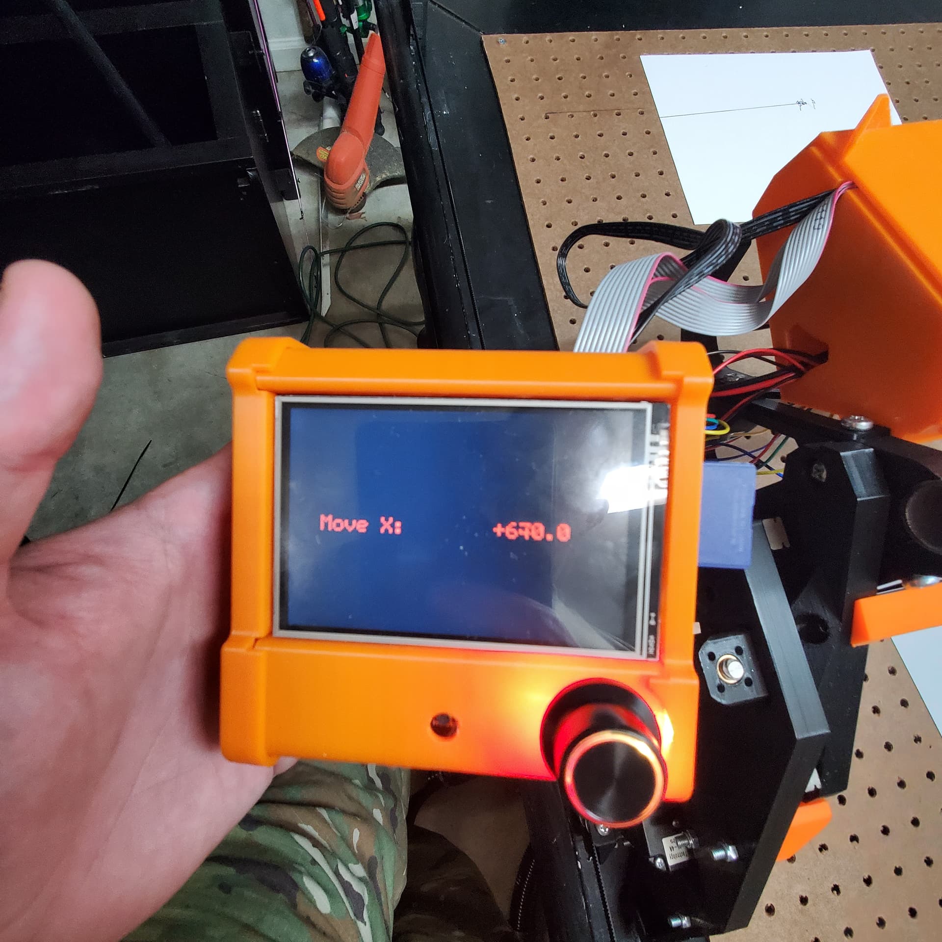

Spent some time wire management last night- boy, are those extension loooooooonnnggg
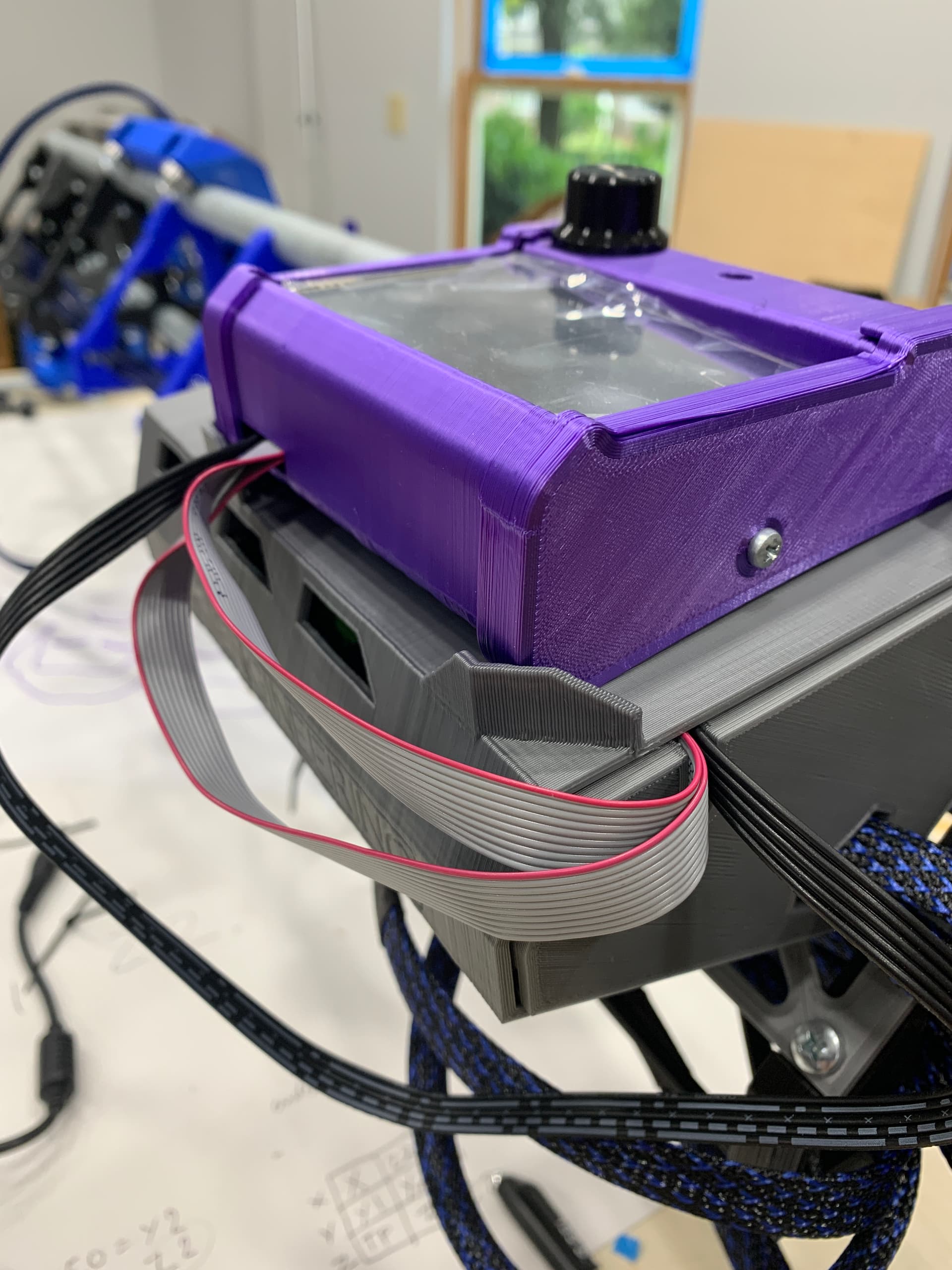
Also- my tft cables are short. Like- ‘can’t position the screen in the cradle the correct way’ short. Not sure if I’m just going to deal, or if I need to source some longer ones.
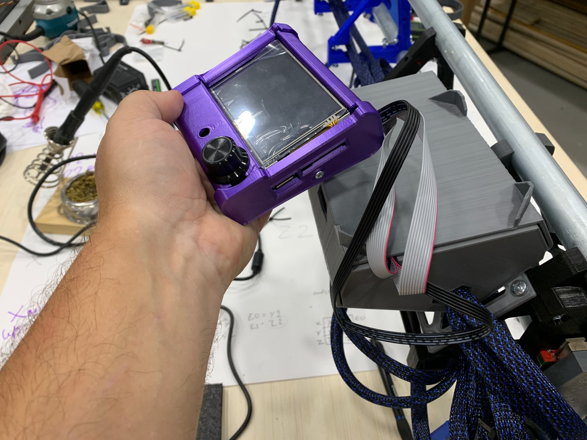
I face my screen sideways and never really move it.
You can go about twice that long with the cables but more than that and you will get errors.
Yeah, but these are the cables it came with. They don’t reach as far as I see in your setup. I can’t position it sideways unless I put the button on the far side
I think I’m going to end up printing a holder that is off to the side and do it that way - move it off the enclosure
I’ve actually been looking at the joystick mod, so may incorporate that
I fought with BTT to at least make them the same length as the black cable, and used to pay to have longer ones made. Neither of those is an option any longer. The difficulty in getting things now has increased exponentially. Most custom things are just not available, and the cost and time has at least doubled. For the first time in 7 years I have taken out loans to try and help this situation, some things are just simply not available right now. I have to buy larger quantities, further out, with higher costs, much higher shipping.
I could make the LCD case have the cords come out of the bottom, or just integrate the screen into the board cover like others have. If I ever pick up my screen it is just to select the file hand hit go, or resume after a tool change.
You have not seemed very pleased with this entire experience so far and I would like to try to help. If you have an order to place let me know and I will thrown in my longer cables if you want them. Or I can devote some time into modifications into some of the printed parts, or finishing the instructions. Let me know what might help make this more fun for you. I do my best to make this right for everyone’s use case and expectations but I seem to have completely missed the mark with you, that bothers me and I would like to change that.
You know what, I actually have another option for you. If you place an order, and want to make some room in your printed part, cut a hole, and flash a firmware edit I can send you a headless connection for your system. Then you can have a touch screen and wireless controls. You will need to edit the files to make room for the antenna and flash some new firmware. Things I plan on doing soon, but I am not going to promise it. So if you want that I will drop it in your order but you would need to do some work yourself on that one. This is going to be my option to lower the cost and improve functionality, but I do not have enough free time to implement it yet.
To keep the cost down I am reusing the old LR2 wire inventory. The new wires will be shorter…but cost probably double. Please understand this is a new machine, just released and I am one guy, trying very hard to listen to all the things people are reacting to and working on improving it. In a few months it should be a stable release.
3 Likes
Ryan
My apologies- I honestly am sorry if I’ve come across as being disappointed or upset with my LR3 journey. Believe me when i say that is absolutely not the case!!
You definitely havent missed the mark. A DIY CNC that has the performance characteristic to rival a commercial product, for <$1000. Are you kidding me- that is PHENOMENAL and i am very very happy to be able to meet that barrier to entry and start my CNC journey.
The build journal is more a running account of my build and my musings of things i encounter during build and use. It isnt meant to be taken as a criticism of the LR3 or V1engineering. Are there differences with my particular ‘kit’ that i’m noticing with other builds? Yes- but supply chain and availability account for that, as in the LCD cables like you explained. It was just a little unexpected to spend 3 hours sorting out my wiring to see my LCD not turn enough to sit the same way ive seen in other builds. but im not upset.
Was the interface not quite what I expected from a CNC interface? Yes, ill admit seeing a lot of irrelevant 3DP stuff on the screen is a distraction and does seem like the software has been ‘tacked on’- but explanations by yourself, Jeff and Dan have shed light on why it is that way. Have I been able to overlook that aspect, and already started producing fairly complex drawings, starting from scratch with png’s and editing gcode using your guides- yep!
Honestly- your concern that you’ve "missed the mark’ with me just shows how invested you are in bringing this technology to everyone for a price-point that most serious hobbyists can meet. Your willingness to correct what are perceived negativeness in my opinion is very telling as to how you treat customer relations and is very commendable.
There is absolutely zero need to go to any of the efforts you’ve mentioned- I am honestly very happy with the process, and the products, and the real-time support.
Again, Ryan, i absolutely love what you’ve done with V1engineering, and the products you’ve built. Stellar engineering and design principles, and affordable.
Regards
Neil
6 Likes
I do sincerely want to make this more ideal. Your experiences here and FB have been noted and I appreciate the feedback. I do want to make it a better experience for you, if possible. I am following along and will help change what I can as soon as possible. Glad to hear you are not as disappointed as I thought. My frame of reffence is changing. I used to be solely focused on the machine’s performance above all else. I am learning more and more to take the build and experience into account.
5 Likes
I used these cables for the screen https://www.amazon.com/dp/B07SR3S2W3?psc=1&ref=ppx_yo2ov_dt_b_product_details and then just extended the 5 pin tft cable with a leftover dupont cable connector kit I had laying around. they’re cheap enough and easy enough to extend.
I then wrapped it all in a 3/8" braided loom. The extra cable helps as I don’t know how to (and am currently not using) use the touchplate z min homing. Basically when I’m lowering the unit to my origin point, I can have the screen right in front of me vs off to the side.
1 Like
Velcro works a charm for keeping the screen in place but easy enough to move if you want