That’s a very good suggestion, thank you. New to Marlin, I had no idea what junction deviation setting does. I’ll run some tests tomorrow. LR3 does the job now, but having fast and smooth moves would make me feel much warmer inside )
1 Like
In the end it was the gcode generated by Fusion that caused jerky movements. Apparently Fusion’s scallop strategy doesn’t like the tabs I added to hold the board while cutting. I replaced scallop with morphed spiral and the movements became smooth. Turning off S curve or enabling classic jerk didn’t help much, I think with classic jerk it was even more jerky.
For the last cut I increased finishing pass speed to 12m/min, but reduced acceleration to 300 and the movements super nice and smooth. Next time I will try 15m/min.
Cutting time is currently down to 50 min for the deck and 35 min for the bottom side. Quite decent for a home made CNC ) One board makes around ~60L of foam powder. Those numbers are for short 5"2’ boards. For a long board I think it would be double, but there is still some room for optimizing the process.
2 Likes
For big stuff like that it is hard to tell but try fast shallow passes vs Deep slower passes. It can go either way. Sometimes saves a ton.
But, you know. If you build a second machine while one is cutting, you can be setting up number 2…twice the production. 
With the increased RPMs of the makita router, my last setting for deep cuts was 6m/min @ 20mm stepdown. I then increased the speed to 120% while cutting, and even that didn’t cause a slightest problem.
But yes I still have to experiment a bit with speed vs depth.
I wonder what your experience is with these couplers for the LR3?
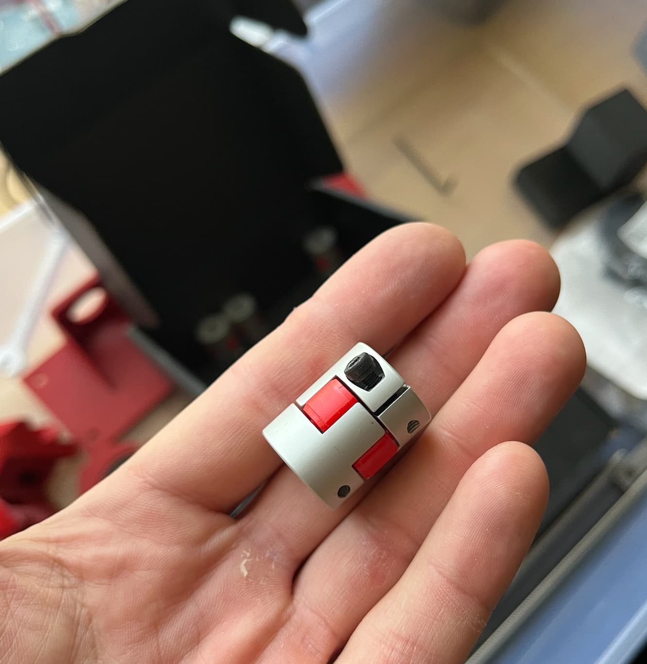
I found several in my junk box and thought they might be useful? They seem to be more rigid than the spring couplers and also probably safer in the situation where you accidentally send your Z too low. The downside is probably that they have more friction to go to their “home” position, not 100% sure if the weight of the gantry would push them down immediately
I don’t think they will offer anything other than the crashing safety. Next time you mess around with your build swap them out and give them a shot. I have some but always forget to swap them. Too expensive for the kits for any benefit they may have.
This is mostly a CAM exercise at this time. Just keep messing with the Paths to see what saves the most time. Obviously reduce travel but with large jobs I think it is more worth it to spend time in CAM to reduce cut time. Waterline vs X vs Y, so many options.
I use these for my 3D printer screws.
They are slightly larger than the spring style ones, so be aware of that as a possible interference issue.
Aside from that, my big worry would be them lifting as you plunge into material, particularly with a downcut bit. They can handle a bit of force pulling on them, but are designed to come apart. They’ll eventually wear, making it easier for them to lift.
Aside from that, they seem to offer a more steady centered rotation, which is nice, and have very little give against stray rotation. Not sure how much actual advantage this really gives, but with the LR2 I did lose a bunch of the coil couplers to being stretched. This has not been a problem on the LR3, and I think Ive already run more jobs on the LR3 than I ever did on the LR2.
1 Like
I’ve installed these couplers today together with 2 start lead screws. The new lead screws don’t crash on power loss or reset and move faster than 1 start screws. IMHO 2 start is the best option for LR3. Besides convenience, another big advantage is the ability to cut the power in case of emergency without the risk of completely damaging the stock.
I still had some skipped Z steps every once in a while even with 1 start screws. Obviously, in this configuration LR3 has more than enough power to lift the gantry so I think the problem must be somewhere else. My current guess is that the dust build up on the lead screws starts causing some friction and since the motors had to be spinning like crazy with 1 start screws, motor torque may have been insufficient at high speed to handle that friction. I could be wrong. It’s very difficult to say for sure. All the noise from the vacuum and the router doesn’t make it any easier to spot exactly when the steps are skipped. After installing 2 start screws, I set top Z speed to 35, which is <50% of the max tested speed. I also cleaned the MGN rails with brake cleaner spray and lubed them slightly with lock lubricant (probably silicone based). Maybe I should use some thicker bearing lube for the MGN rails, not sure. I’m afraid that thick lube could mix with all the foam dust and get all that dirt inside the bearings. After cleaning everything, I dry-ran my usual program with 2 start screws for about an hour and didn’t get any Z issues. Fingers crossed.
Another idea for the skipped steps is that I have acceleration ramped up too much for Z axis to get smoother movements. My acceleration for XY axes is set to 300, and Z is set to 250 (so almost the same), while the top speed of Z axis was 16 times lower than X or Y. The skipped steps could be happening due to inertia of spinning very fast in one direction, then reversing and spinning very fast in another direction. I usually get skipped steps on the last stages of my cuts, where I use high speeds and lots of Z movement is happening. After about 1.5 hours of cutting, my Z is sometimes 2-5mm off, so not a whole lot. But it usually means stock going to the trash.
I will try to lower the Z acceleration in Marlin, lower the speed for my finishing passes and try one more cut tomorrow.
Probably from trying to spin the steppers to fast and running out of torque. the trade offs are speed vs power. The slower they are the stronger they are.
35 to you is like 70 to a 4 start(extremely fast). Try going slower. RPM vs Torque.
Good idea, take my stock settings and divide by 2.
1 Like
2209 drivers rated @ 28V means that 28V is the max voltage I can send to the motor? Asking for a friend :))
You need to worry about your control boards max voltage before the drivers.
But yes they will work from 4.75v to 29V. Might just want to stick to 24V to be safe.
Instead of trying to speed it up just try to use less or shorter Z moves in your CAM.
Even with 4 start screws Z speed is the absolute last concern I have in any of my Jobs. 100x more XY moves to optimize for me.
Well, to get a nice 3d finish the endmill kinda needs to move along the face of a model. In my case Y moves ~157cm tail to nose and Z moves ~8cm top to bottom during the same time. That’s almost 20:1.
In general, I can lower the Z speed no problem. That will probably add 2-5 minutes to my 90 minute job, so not a big deal. I started playing with increasing Z acceleration when I had those jerky movements from Fusion’s G code. It appears to be mostly related to the scallop method in Fusion, other methods produce a more fluent gcode. On the other hand scallop gives me the best board finish with the least post processing afterwards… so in the end after trying all the other 3d methods in Fusion, I went back to scallop and agreed to live with the jerky motion. Increasing Z acceleration helped a bit with that, so I left it there.
What surprises me is that X and Y are flying around at high speeds with quite a bit of resistance and don’t skip. And Z has always been a problem since day 1. Hopefully reducing speed/acceleration will fix it.
Here is what I tested as a max, Real world testing of 12v vs 24v - #14 by vicious1, 12v Z 4 start 63mm/s, 24v 4 start 80mm/s with stock screws and accel. Z accel is very low, but needs to be.
So with 4 start screws you will get 4x’s slower than XY, with 1 start 16x slower, 2 start 8x slower.
Steppers are just not high speed motors.
With less start screws you can get higher accel, so in the end they might be quicker for tiny moves, but 4 start will always have higher top speed.
1 Like
You could move to ball screws and get higher speeds.
1 Like
I tested for max Z speed again today. With Marlin setting at 70, it worked fine. At 80 one of the motors skipped on the way up. So I set my max to 35, which is half of last working test. Maybe thats too optimistic. I will go lower and see if it helps.
I think the biggest challenge is keeping the screws clean and free of dust. If its covered in snow, ball screws are probably not going to last long  Today when one of the motors skipped during the cut, it was on the side next to the wall - a difficult to reach place with a vacuum while everything is moving. I clean the other one periodically while milling.
I must admit cnc milling is a bit more complicated than I thought.
First, I noticed by boards don’t look 100% as I designed them. Looks similar, but something is just not right  So I started measuring. And in some cases, the board is thinner by… quite a bit, like 4mm… than it should be.
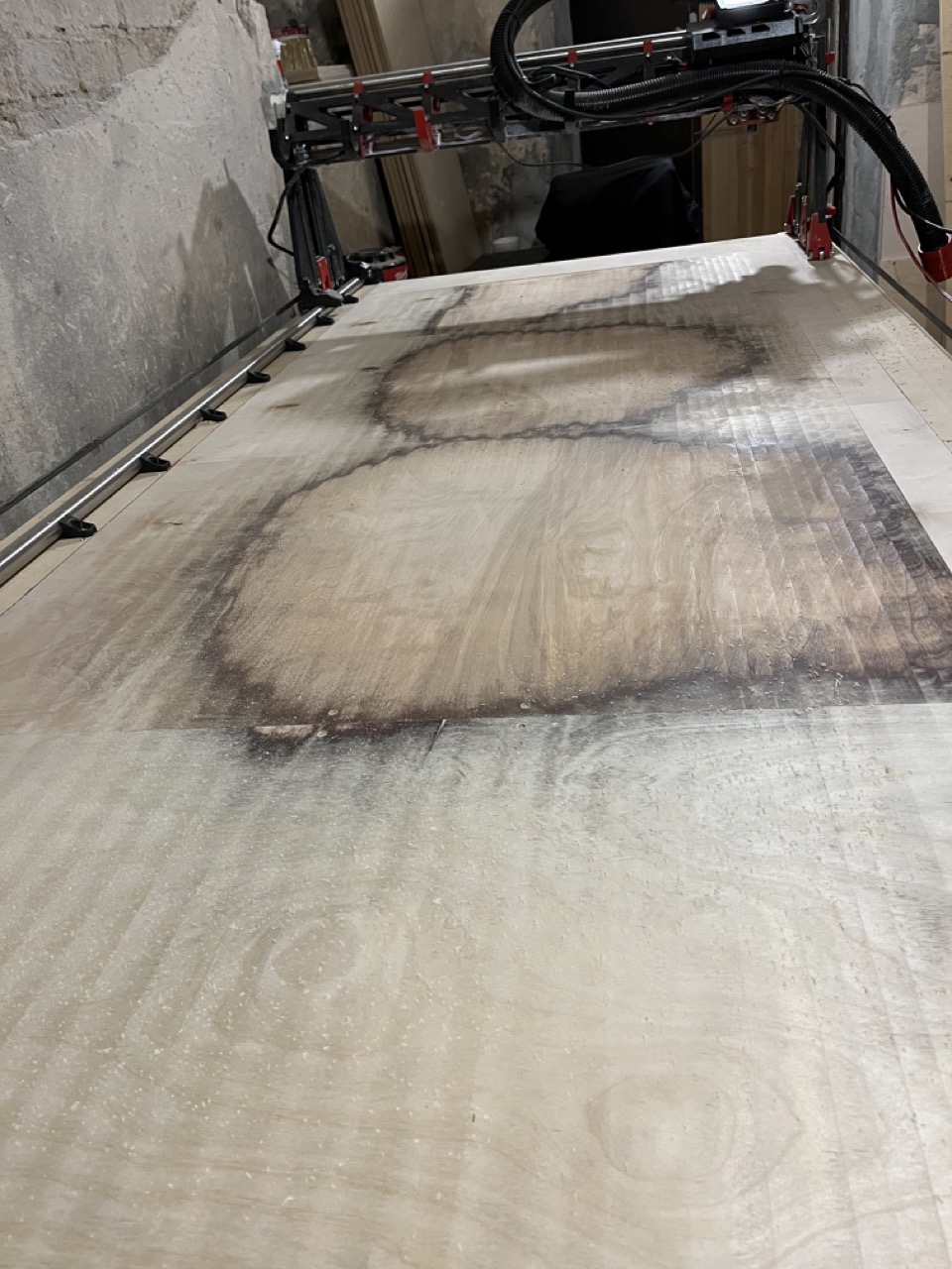
So I started driving LR3 around the table and measuring the distances and yes, the table was not 100% even. I found a few spots that were higher by 1.8-2mm than my zero position. Apparently humidity played a certain role in that, as I moved the cnc to the basement which is a lot more humid, so the old wasteboard absorbed some water and started sagging etc.
Thing is… it’s off by 2 mm on one side, then after cutting the first side I flip the surfboard over and cut the other side, and it’s 2mm off on that side as well. So 2 becomes 4. And the surfboard nose is less than 1cm thick, so basically I loose half of the nose thickness. Not cool!
I bought some thicker plywood and replaced my table top with that, and then surfaced the whole thing with a surfacing endmill. Doesn’t look pretty, but at least it’s even(er).
Next surprise: I tried to make a stand for the surfboard lamination. Found a few ideas online, made a fusion sketch and here it is:
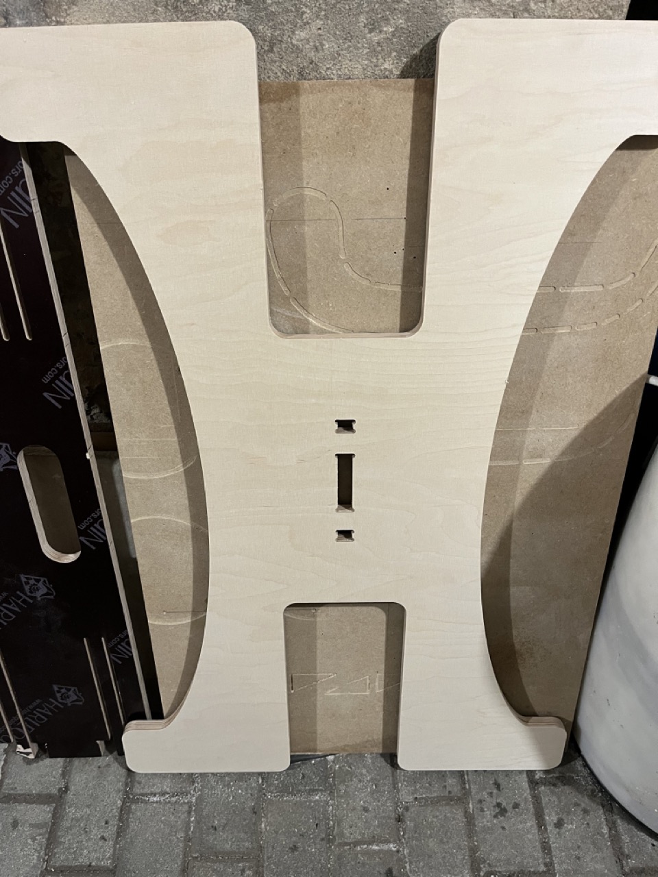
This one was cut with 6mm endmill, 2m/min feedrate and 3mm 2D contour stepdown. Looks pretty nice. Except the hole in the center is supposed to be 18.3mm, and it is somewhere around 17.3mm or so. Roughly 1mm narrower than it should be. And the other 2 holes seem to have similar issues, although they are more difficult to measure. Then I started measuring some other plywood parts that I cut, and it appears that all the holes are up to 1mm narrower than they should be, and all the solid parts are ~1mm wider than they should be. I was like WTF maybe my endmill is 5mm instead of 6 and I didn’t notice it! Measured the endmill - it’s exactly 6! Damn.
Then I made some tests and apparently cutting speed plays quite a big role in accuracy. If I cut reallllly slow, the tolerances are more or less what they should be. Or at least so it seems, I haven’t had the time to test it very thoroughly. So I guess I should use a finishing pass and make it go sllllow. You live and learn. This is a time consuming hobby.
2 Likes
You do not need to go slow you do need to use a finishing pass 100% of the time for dimension cuts.
In wood something like 0.5mm at full depth is a good starting place for the finishing pass.
With that same note though. Make sure you have reasonable tolerances for wood. It moves a lot. Most projects, 1/32"-1/16" is way more than enough.
Plastic and metal can be held to higher standards but as you see humidity can change dims very easily in wood.
If I’m using 2m/min with 3mm DOC for the milling of the contour, what would be the recommended speed for the finishing pass? Leave it the same? I actually used 2x speed for the finishing pass as I thought there would be hardly any resistance, maybe not a great idea.
=33.3333mm/s That is fast. You can go deeper and a bit slower. I use teh same for teh finishing pass just full depth 0.5mm cut.
The firmware is limited to 50mm/s. Speed does not equal accuracy. You will only save a few seconds so just stick to the same speed.
Beyond that do some actual test, everything is completely up to YOUR build, no two are the same. so real tests give you your numbers.
I found a mistake in my model, where one of the hole edges was offset 0.15mm in the wrong direction. That’s definitely part of the problem. I will try a new cut tomorrow with the fixed model and adjusted speeds, will see how it goes.
1 Like