You should be able to do a full depth finishing pass. That should give you a good finish and accuracy. I’m not sure what speed, but it is only just barely touching the material (if things went right). So I would start with the same speed and just full depth.
It seems like the problem was with the milling bit in the end. I ran the finishing pass 3 times at different speeds and couldn’t get the accuracy anywhere close enough. After changing the milling bit it worked from the first attempt.
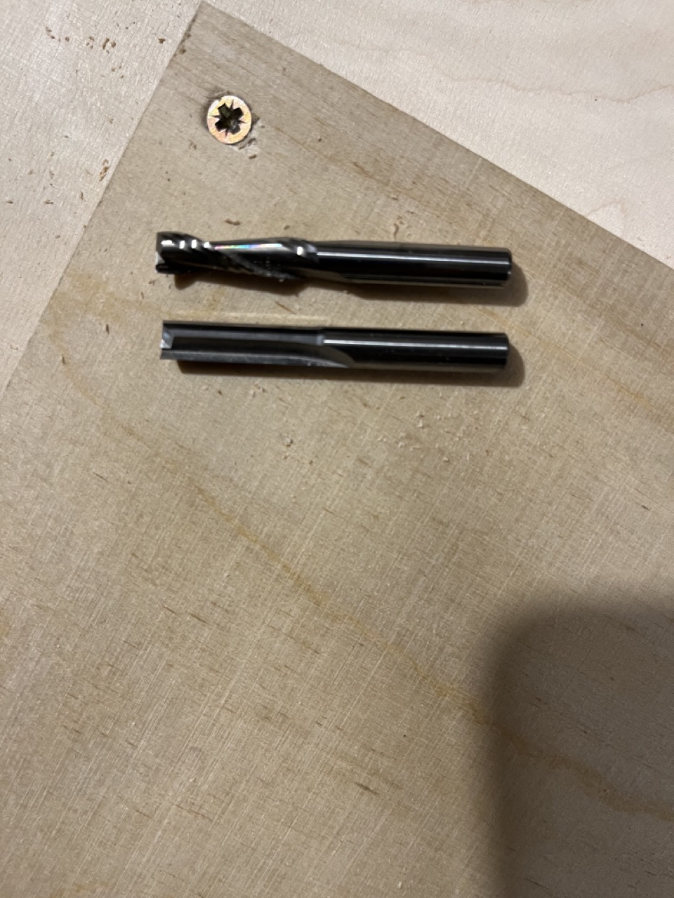
The one at the top was causing problems, the one at the bottom seems to be way more accurate for cutting plywood. The downside is that it seems to be much louder as well.
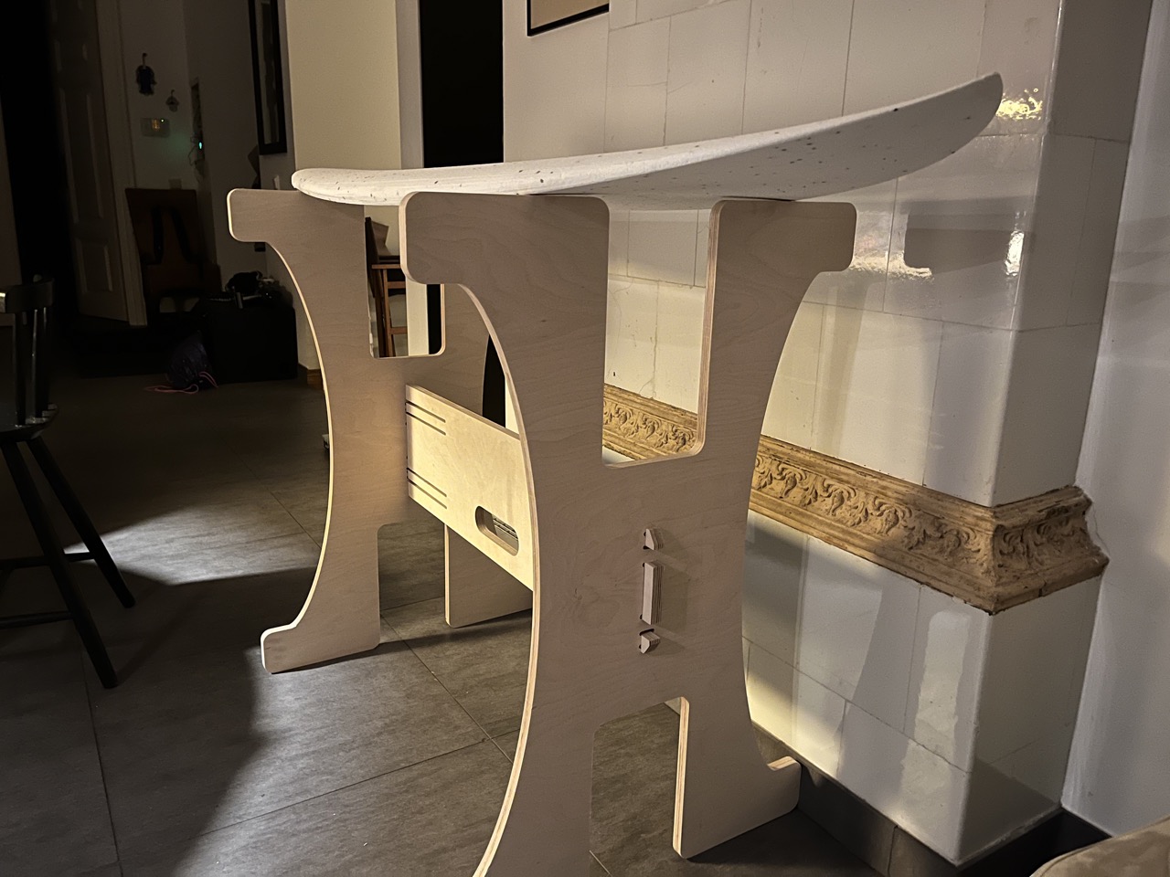
When the cuts started coming out accurate enough, I was able to assemble the stand.
I will still need to figure out the proper dog bone hole diameter, as the endmill is making strange sounds when it enters the hole. I used 6.5mm for the 6mm endmill.
3 Likes
Your CAM program should offer to do that automatically for you. Usually you get a few options as well, I use the smallest one.
The straight mill also tends to need much slower federates so play around with it a bit. Odd that your upcut isn’t the better one. The next one you should get is a single flute upcut for the wood. Our routers are generally too fast for two flute or more.
I’m using Fusion 360 and I don’t think it has any support for dog bones, at least not officially. I heard there are some 3rd party plugins, but they seem to be buggy and only offer one position for the hole.
What CAM program are you using that does this automatically? Creating those holes manually every time is indeed a bit time consuming…
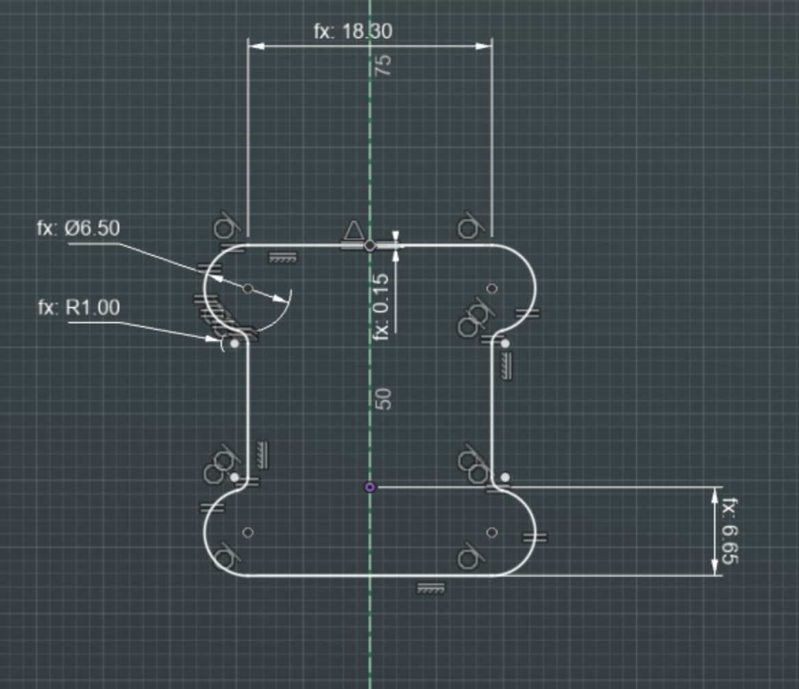
It isn’t quite automatic with estlcam, but you can choose the overcut tool and click on the corners you want to overcut. It doesn’t do the same dogbone you have in that picture. If the ones in your picture are at 90degrees to the side, the estlcam ones are at a 45. That ends up making them just a little smaller.
2 Likes
That is it, overcut in ESTLCAM. Works great.
1 Like
I use one of the addins for fusion. Most of the time it works well, let’s you pick the endmill size and add extra if you want, but sometimes it fails on certain corners and I have to run it again and pick those out specifically. Weird.
Thinking about how to better handle dust related issues, I came across this:
These rails are pricey but in general igus products are known to handle dusty environments well. I think they have 1:1 MGN12H replacements. Anyone tried them out yet?
Fun fact: The MGN rails on one side of my machine get 10x more dust than the rails on the other side. I think that’s related to the direction of endmill rotation somehow. The stock is always centered on the table.
1 Like
Here’s a link to a script for fusion and an article (dated 2017) discussing very minimal dogbones as the neatest solution:
And they are built in to Kiri:Moto so no need to draw them in your CAD program. just tick the “dogbones” box and watch the magic happen! ![]()

3 Likes
I have the exact intermittent problem you did. It really started to fail more often when I put the cover on the case. I’ll try pull up resistors tomorrow and report back
1 Like
Hey!
I’ve been out of the country for 6 months and my LR3 was left to rust in the basement during this time. I am now back to cutting my boards (did 4-5 last month) and it’s going pretty well. One minor issue I noticed is that there is probably some slack in the Z axis and I can’t figure out where it’s coming from.
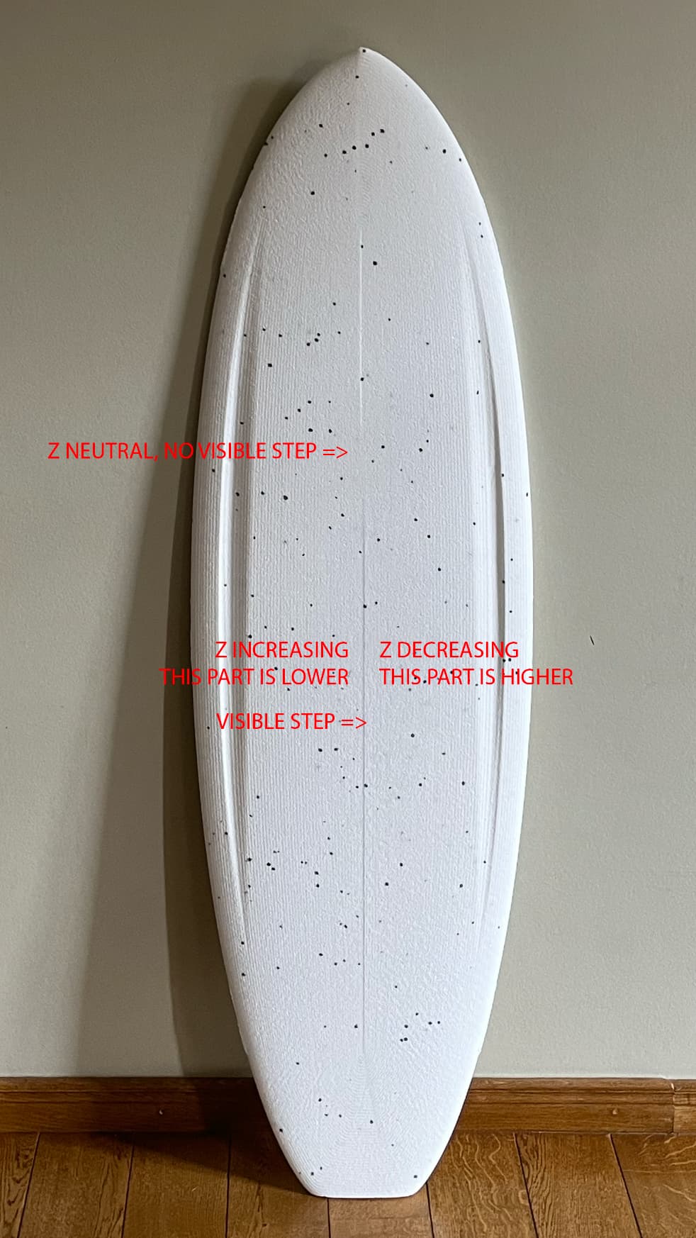
If you look at the pic, there is a visible step at the center of the board. At the bottom, the right side is slightly higher than the left side. At the top, it’s the other way around. The step is not big, maybe around 1mm or so. My first thought was that I moved the stock by accident, but I now have at least 3 boards with the same step and it’s becoming obvious that this is an issue with the machine. The deck of the board is completely flat in the model.
The cutting program is a morphed spiral generated by Fusion 360. The endmill is basically spiralling around the center of the board in CCW direction, doing really long ellipse shaped passes.
I think that there is a little play somewhere in the Z axis, and the endmill ends up in a different position depending where Z is travelling from. I’m pretty sure that if I reverse the direction of the spiral, the step would get mirrored as well.
Not really a big issue, but I would appreciate any ideas if you’ve experienced anything similar.
1 Like
Check the grub screws. ![]()
With that step being at the exact center line, I have a feeling it is CAM related. Try opening your gcode file in a gcode visualizer to see if it shows up. You can add a finishing pass as an XY direction to just that section of your board to level it out.
That is freaking beautiful, I think that is the first full sized board I have seen made with one of my CNC’s yet it was one of the first 5 projects I wanted to try.
Philip is probably right, though, The coupler grub screws are a prime suspect. As well as hitting your Z bearings with a light lube.
Philipp, if you please. It’s the Greek spelling, meaning lover of horses (platonically). ![]() (My dad is a professor for ancient history, specialising in Romans, being able to read Latin and old Greek fluently. Weird guy.
(My dad is a professor for ancient history, specialising in Romans, being able to read Latin and old Greek fluently. Weird guy. ![]() )
)
do you cut one side, then the other, I am noticing the left side nose and the right side nose are dramatically different cuts!

1 Like
Sorry, I just started with my coffee when I wrote that.
1 Like
For a “lover of horses”, you’d think he’d have found one…

For you unwashed heathens, that’s a statue of Pheidippides (AKA Philippedes) along the Marathon road. He’s the poor sod who died after running the first marathon.
2 Likes
The step is right in the center because … how do I explain this in English… this is where the opposite direction lines meet. On the left side, the endmill is traveling nose to tail, and on the right side the endmill is travelling from tail to nose. Z axis travel also becomes opposite, which creates the step I think. I will double check the gcode. The model is completely flat in the render:

Thank you! It took a LOT of effort to get the 3d model right though… I think I spent more time on 3d modelling the board than I spent on printing/assembling/testing LR3. I started from zero 9 times and had to learn all the workflow of fusion surface modelling from scratch. Was great fun apart from being ridiculously time consuming.
I do clean those MGN rails with brake cleaner spray, then compressed air, then lube with silicone spray every 5 cutting hours or so. Foam dust is still an issue. If I don’t clean/lube so often, the Z movement becomes a little bit jerky with a slight oscillation on the way down, creating funny little ripple/wave patterns on the board ) But spraying some lube and running the final pass takes care of the issue easily.
I will double check the screws!
This is probably just a poor photo quality or a shadow that you are seeing. Here is a more close up pic:
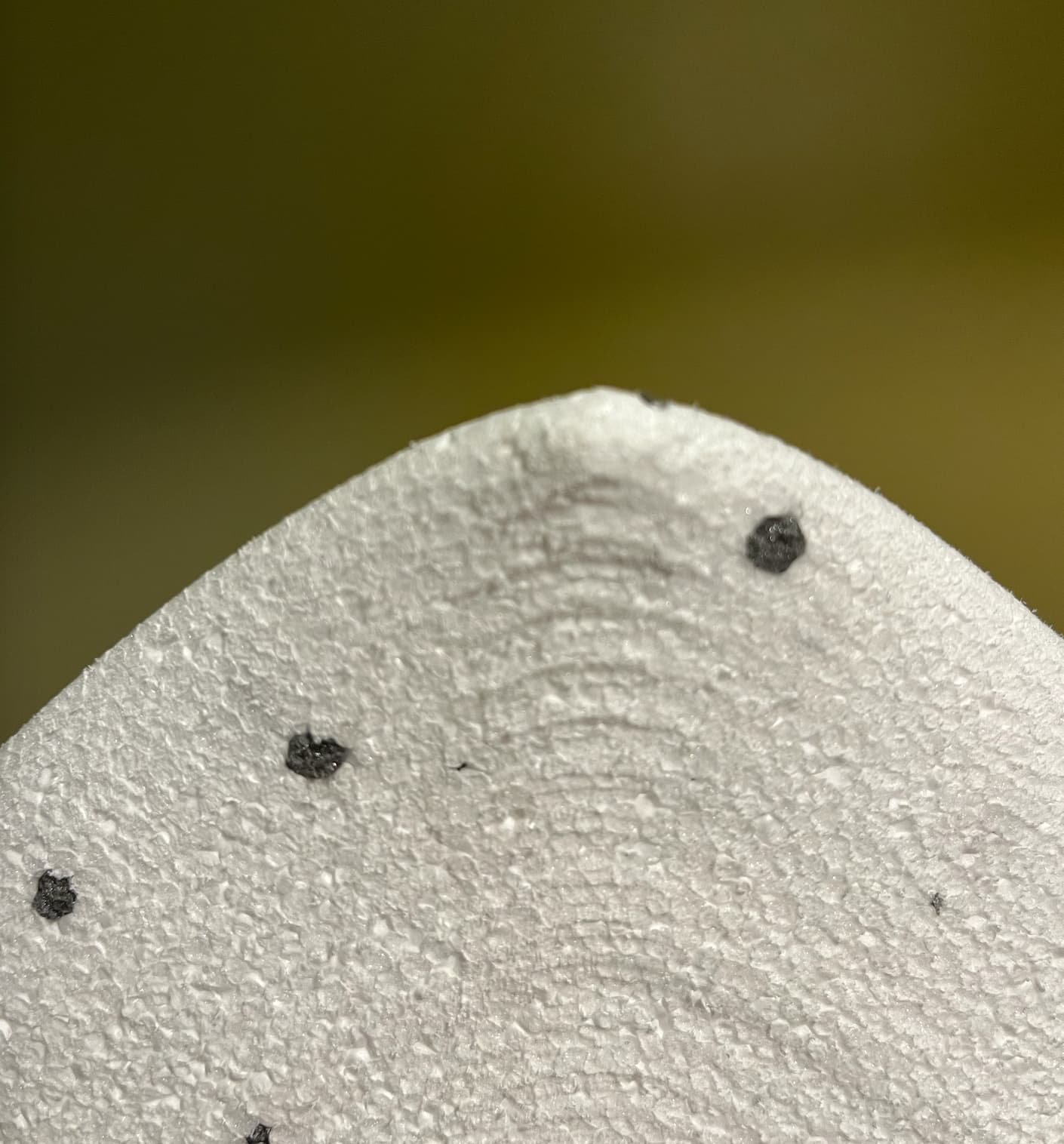
3 Likes
Yeah, gut reaction is that if the issue is at the inflection point where the Z-axis travel is changing direction, you likely have a loose grub screw or two. That might explain the apparent backlash (too low on the way up, too high on the way down). That, or your couplers have gotten… springy.
1 Like