Oh, you don’t believe me?!
10 Likes
Nice now relax and enjoy the rest.
Once I had the LR drawing, I started to really enjoy it, I was a little tightly wound for a while. Tidy up the wires more, and fix some little things.
2 Likes
bwhahahahahahaha, Oh i believed you, i just wanted ZEN video P0rn…
1 Like
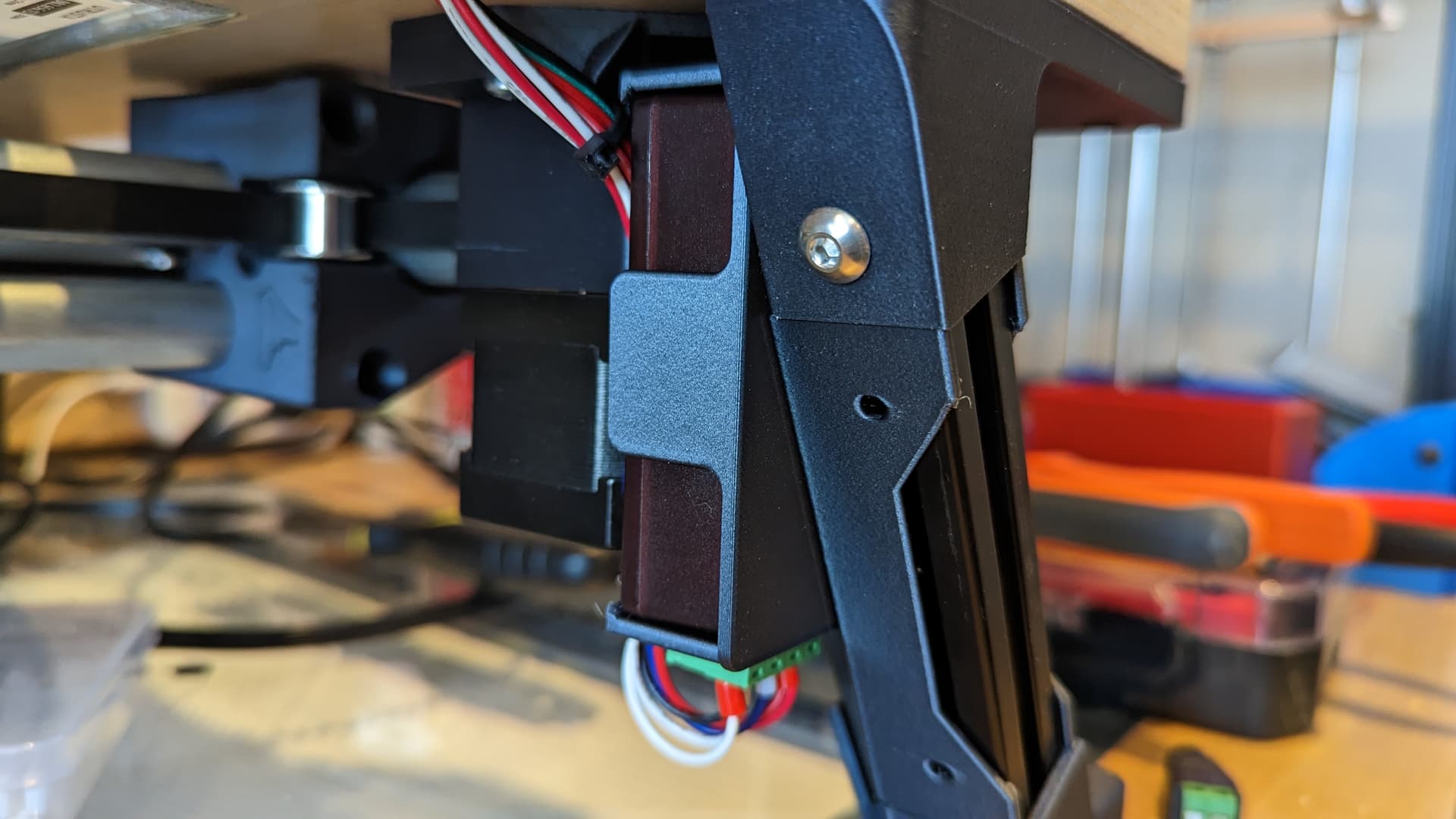
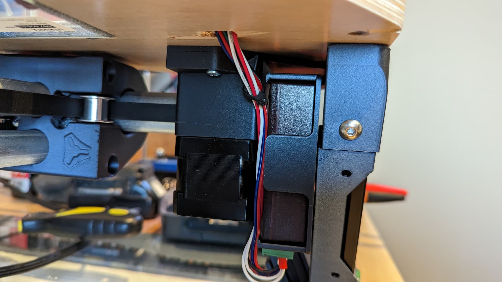
I designed a pretty functional electronics case. The leg/2020 choice made it a little harder, but I think it is doable.
I am going to mount the esp32 fluidnc board on the front left leg. The endstops are there.
I am going to mount the LED controller on the front right leg. I need to run +12V and ground from the esp32 board to the led controller. And I need to connect the LED controller into the LED middle layer for the lights.
I am trying to decide how to route the second stepper motor wires. And the power for the LEDs.
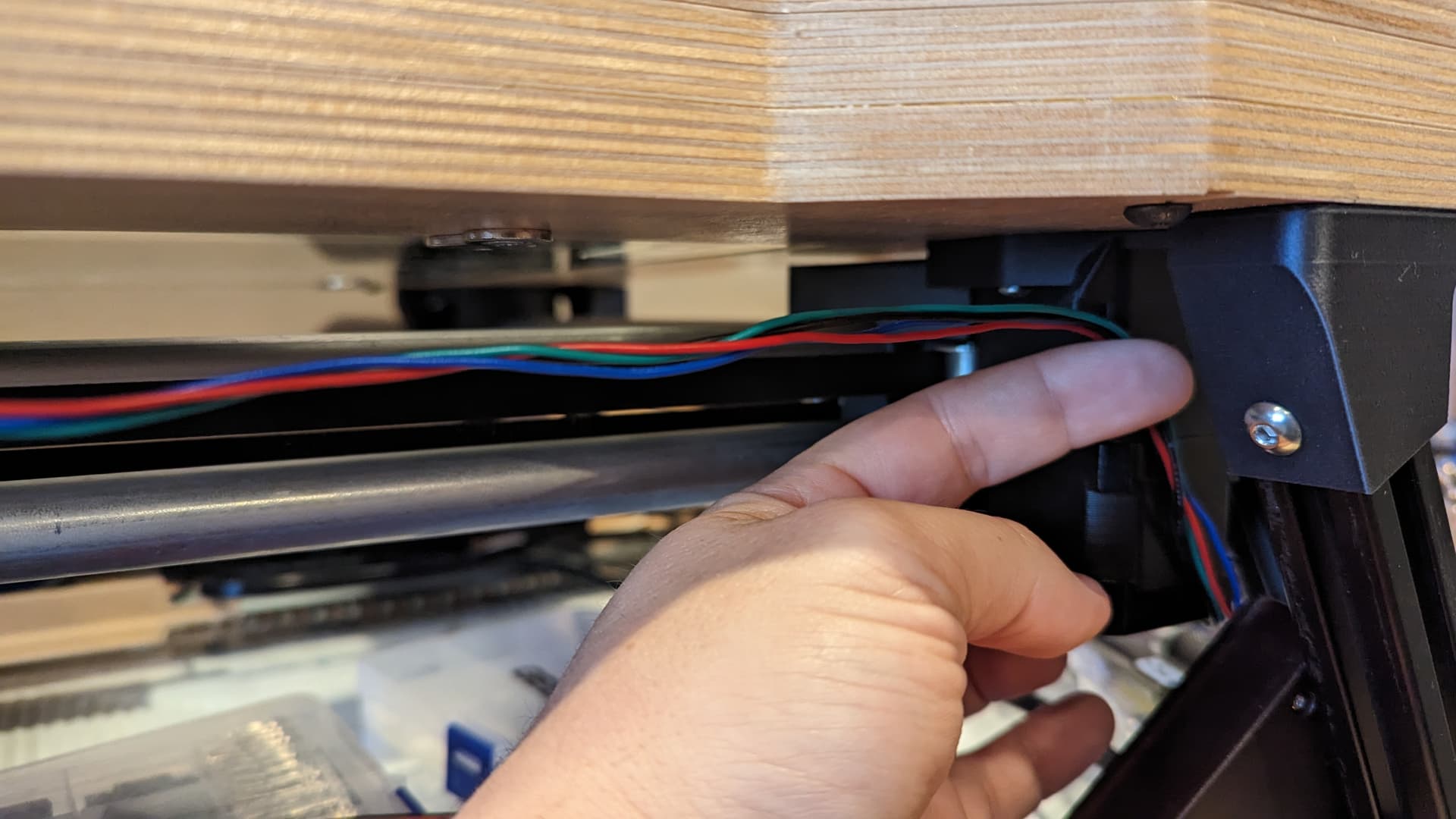
There are these little zip tie spots, which seem like they were meant for this. But they are just a tad low. They would work, but they aren’t extra fancy.
I could dress up the cable a little by adding some of that accordion wire wrap stuff. Or I could print a little part to lift the cable a little higher. It is about a half inch below the surface.
Or I could cut into my table and route the wires in front of the LEDs in the middle layer.
I could design and print something I could glue to the bottom to manage the wires.
Thoughts?
If I hear nothing, I think I will try to add some wire wrap. If I hate it, I will add some glue on clip to lift it up.
1 Like

Like drill a little hole on each side, that seems easy?
If not I can model up some small screw in clips for you.
2 Likes
The middle layer is 0.5". The led strip is about that size. I was thinking I would have to route in a channel, but maybe they would be fine just hot glued down.
I have to make one hole already for the leds.
I can model some clips too. I have the machine sitting in front of me.
I’d cut a groove in the bottom of the table deep enough to inset the wire in it. Then use silicone blobs to hold it in place.
1 Like
That is an option too. But I already finished it, and I hope I don’t have to take everything apart again.
Little surface clips would be my second option, then.
1 Like
A second hole and a few wires should lay in the corner of the LEDs without casting a shadow, I think. But maybe the LEDs are further forward from what I am thinking. In my table, they are about 1/2" from the outside. I think yours are a few inches.
What does it look like when standing back 10’-20’ resting on a conference table, the way someone approaching with fresh eyes, for the first time, will see it? Considered downlighting to lure/hook them in ![]()
Would L bracket wood/plastic/metal fascia along the perimeter help, hide wiring and other mechanisms? Or more ply. Either way could be mitered 45 inwards (like ship’s hull). Maybe you want people to see the inwards given the audience we have. I’m going out of way to make the insides visible for this reason.
Accomplished cable braiding seems to garner much appreciation/respect.
1 Like
Now you can put a figure with a magnetic bottom and they’ll skate around the top of the glass (ice). ![]()
Great job! Keep going. Now I want to build a zen table/end table. Darn it. Another project on the list.
2 Likes
For your under-table wire management you could get some black plastic raceway. Usually comes with double sided tape and the cover just snaps closed.
2 Likes
I really like all the input. Thank you.
I took the top off. I might as well work on the leds while the electronic mounts are printing.
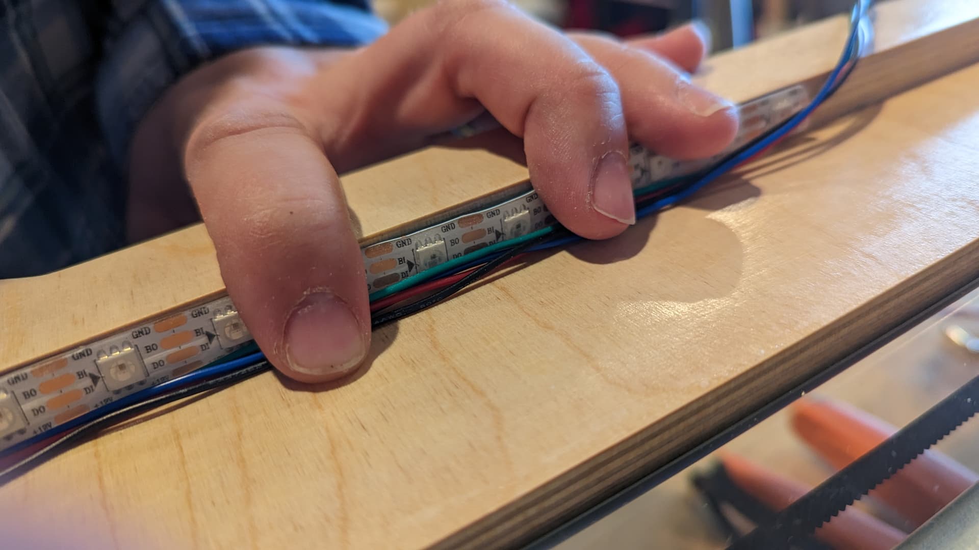
Here I have the 4x stepper wires. I need 2x more for the led power.
In this pic, they are crumpled down, but not flat. That might be ok. You won’t be able to see the leds or the wires directly. Just any shadow that the wires might cast.
Here I have flattened them out. I have some 4 pin ribbon cable, but I might just try hot snot to hold these down here.
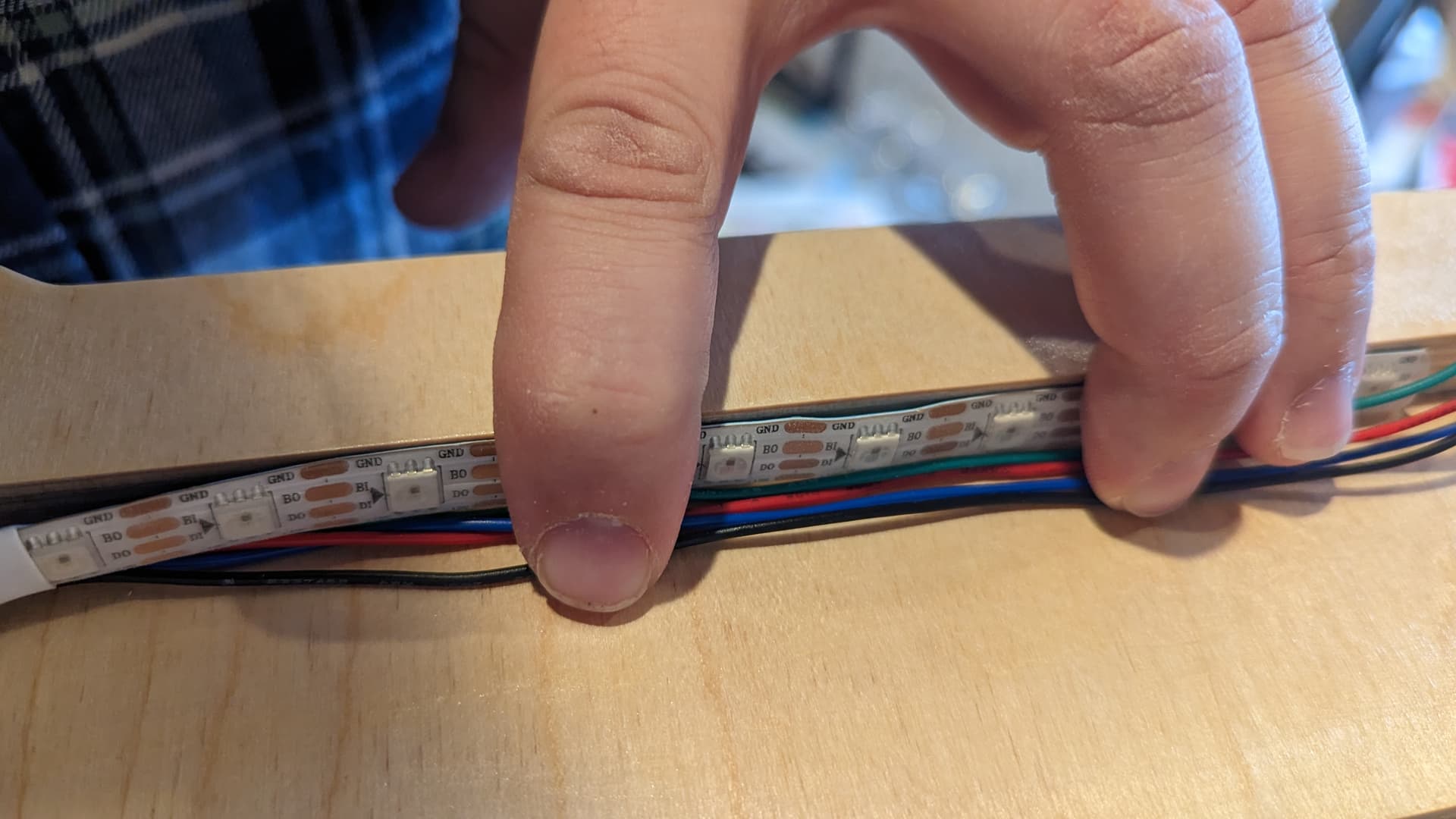
This gives you a sense of the scale of the led cavity. The top opening is a touch smaller than the bottom. So I don’t expect many people to be able to see the leds, just the lit up baking soda.
I wish I would have figured out where to put these and just carved a channel with the cnc. That would have been an extra 5 mins, max.
3 Likes
I actually have some of the silver aluminum track I used for LEDs. That could work too.
1 Like

Leds installed. I am going to try to just hot glue down the wires. That should work fine.
If it doesn’t look good, it will be a fun group project ![]()
7 Likes
That round corner inside looks great with the LED’s
1 Like


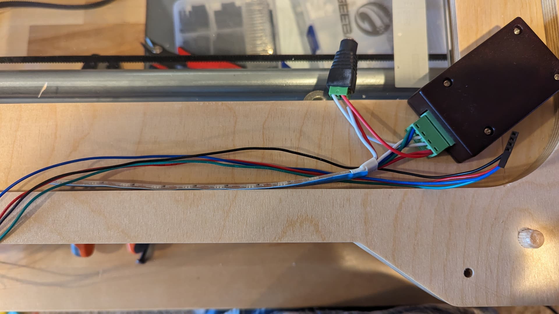
LEDs are wired up. Getting power from the esp32 board. The wiring and mounts ended up reasonably tidy.
The LEDs are visible at one angle. The wires don’t seem to have an impact. Still, I will add a channel in the design for them.
I am missing my 4 pin jst-xh connectors. I should have some from digikey on Monday. Then I can do the final motor wiring. Actually, I just need the housings. Maybe I can find some in my scrap bin.
I found some stuff at home depot to fill in the gaps around the bottom glass. It is meant for filling cracks in concrete before covering with grout, I think. I got the smallest stuff and cut it in half.
8 Likes