I know a lot of you don’t like sensorless homing but it does make this scenario a lot easier.
@jeffeb3
Great point. May do that.
Question to research: How to edit firmware so “Home XY” button only homes one and not the other?
I actually used sensorless homing for quite some time on LR2, and switched to the sensors (switches) because it was part of the default design of LR3. I’m pondering on this.
PS: While using sensorless, I did have random (but fairly routine) times when it failed and the stepper would just keep pushing.
Hmmm you mean on the screen? I am not sure. My guess is that there is a way to disable X homing. There is also one magic place in the code where thay menu item sends a command in gcode.
If you are using something else, a macro with the G28 Y/nG28 Z would work.
Yes, that magic place is what I had in mind. I am apparently not alone in finding the editing of the TFT firmware a bit confusing and overwhelming.
If I unbend the driver pin for sensorless homing one of X/Y drivers, but not the other — would I get a mix of sensorless homing and switched homing?
Pretty sure I’ve seen folks doing xy only so I think so. I home xy and home z upwards to square the machine.
You have to tune the sensitivity to within 5-10 to get accurate repeatable results otherwIse you get false triggers or gantry crashes.
You also need to enable sensorless homing for that driver/axis. Marlin tells the tmc driver to enable it.
Thanks, however, you may have misunderstood. XY only is a default button in my TFT, but my issue is needing “Y” only (“X” only after the proposed hopeful change).
UPDATE: I designed a new end stop switch holder for the (formerly X) new Y axis. So I can do the default XY homing button.
Thanks.
I am seeking to document here my firmware edits & hardware changes, in my successful process of …
…swapping X and Y axes on a Lowrider v3 with dual end stops, with an SKR Pro 1.2 main board and BTT TFT35-e3 v3.
MARLIN FIRMWARE EDITS
In configuration_adv.h, there were five (5) edits. I changed the following:
- Uncommented “#define X_DUAL_STEPPER_DRIVERS”
- Uncommented “#define X_DUAL_ENDSTOPS”
- Commented out: “#define Y_DUAL_STEPPER_DRIVERS”
- Commented out: “#define Y_DUAL_ENDSTOPS”
- Changed “#define X2_USE_ENDSTOP _XMAX_” to “#define X2_USE_ENDSTOP _YMAX_”
Here are the “before and after” code sections:
BEFORE:
//#define X_DUAL_STEPPER_DRIVERS
#if ENABLED(X_DUAL_STEPPER_DRIVERS)
  //#define INVERT_X2_VS_X_DIR    // Enable if X2 direction signal is opposite to X
  //#define X_DUAL_ENDSTOPS
  #if ENABLED(X_DUAL_ENDSTOPS)
    #define X2_USE_ENDSTOP _XMAX_
    #define X2_ENDSTOP_ADJUSTMENT  0
  #endif
#endif

#define Y_DUAL_STEPPER_DRIVERS
#if ENABLED(Y_DUAL_STEPPER_DRIVERS)
  #define INVERT_Y2_VS_Y_DIR     // Enable if Y2 direction signal is opposite to Y
  #define Y_DUAL_ENDSTOPS
  #if ENABLED(Y_DUAL_ENDSTOPS)
    #define Y2_USE_ENDSTOP _YMAX_
    #define Y2_ENDSTOP_ADJUSTMENT  0
  #endif
#endif
AFTER:
#define X_DUAL_STEPPER_DRIVERS
#if ENABLED(X_DUAL_STEPPER_DRIVERS)
  //#define INVERT_X2_VS_X_DIR    // Enable if X2 direction signal is opposite to X
  #define X_DUAL_ENDSTOPS
  #if ENABLED(X_DUAL_ENDSTOPS)
    #define X2_USE_ENDSTOP _YMAX_
    #define X2_ENDSTOP_ADJUSTMENT  0
  #endif
#endif

// #define Y_DUAL_STEPPER_DRIVERS
#if ENABLED(Y_DUAL_STEPPER_DRIVERS)
  #define INVERT_Y2_VS_Y_DIR     // Enable if Y2 direction signal is opposite to Y
  // #define Y_DUAL_ENDSTOPS
  #if ENABLED(Y_DUAL_ENDSTOPS)
    #define Y2_USE_ENDSTOP _YMAX_
    #define Y2_ENDSTOP_ADJUSTMENT  0
  #endif
#endif
Firmware Download:
-
If you were using the V1 Engineering LowRider Dual Endstop firmware.bin file, and you are OK with a precompiled copy of it that has the changes for swapping X & Y, as detailed above, then you can use the firmware.bin file provided in this listing (link below). If not, you may tweak the included editable source Marlin folder provided. It was made based on “Marlin_V1CNC_SkrPro_DualLR_2209_2.0.9.2_513-src.zip” which was downloaded from V1 Engineering, and is renamed as “V1CNC_SkrPro_DualLR_2209-2.0.9.2 (SWAP X & Y) 2022-06-21.zip.”
-
Firmware Download Link: http://design8studio.com/files/V1CNC_SkrPro_DualLR_2209-2.0.9.2-SWAP-X-Y-2022-06-21.zip
HARDWARE CHANGES
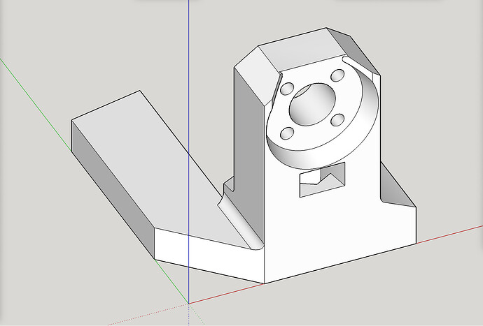
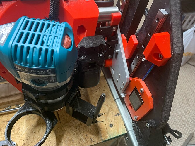
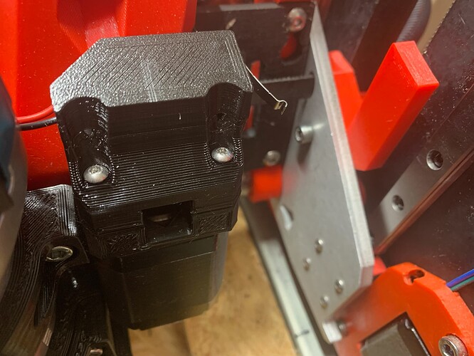
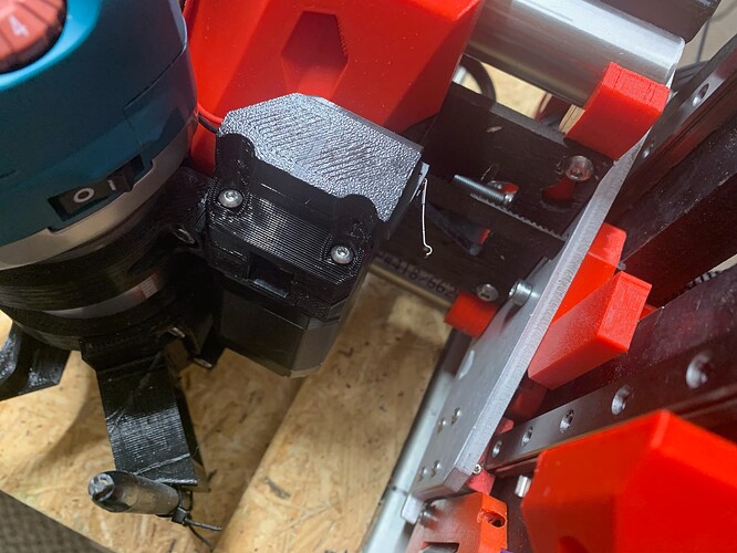
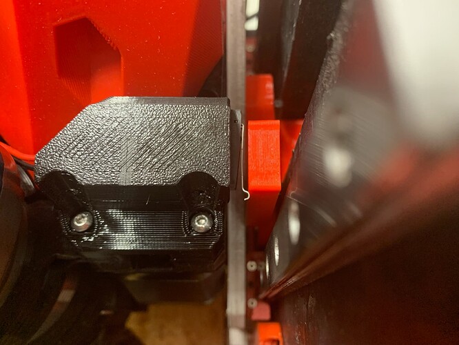
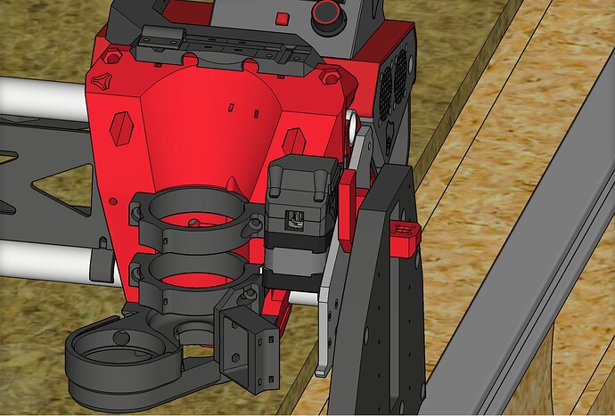
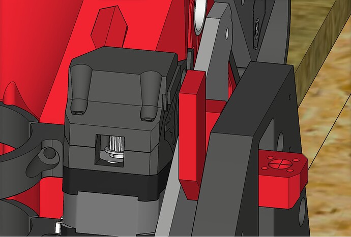
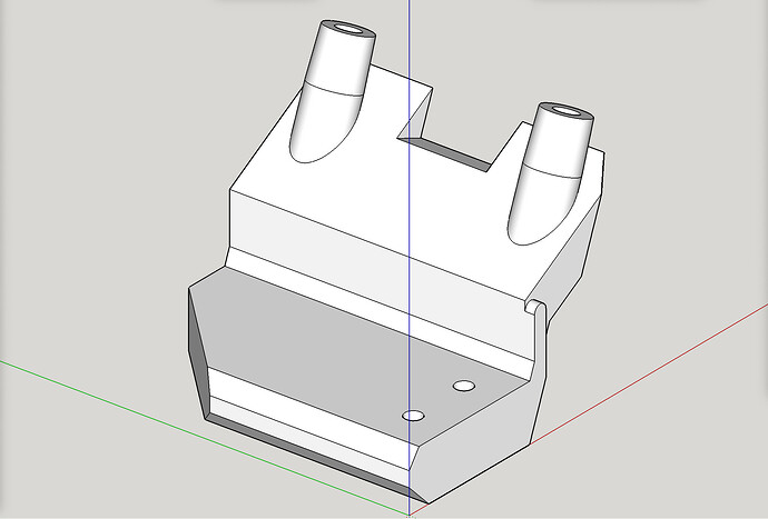
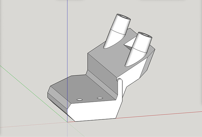
- I moved the former X end stop switch (which is becoming the new Y end stop switch) from the left side of the LR Core to the right side of the core, attaching it to a newly designed & printed end stop mount that attaches to the former X stepper motor mount, which is becoming the new Y stepper mount. I also re-ran its wiring accordingly.
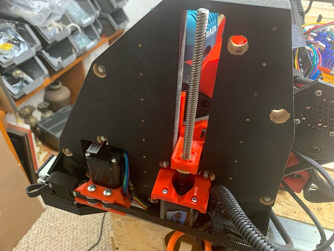
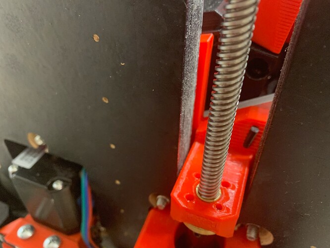
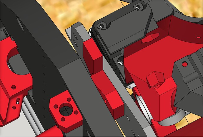
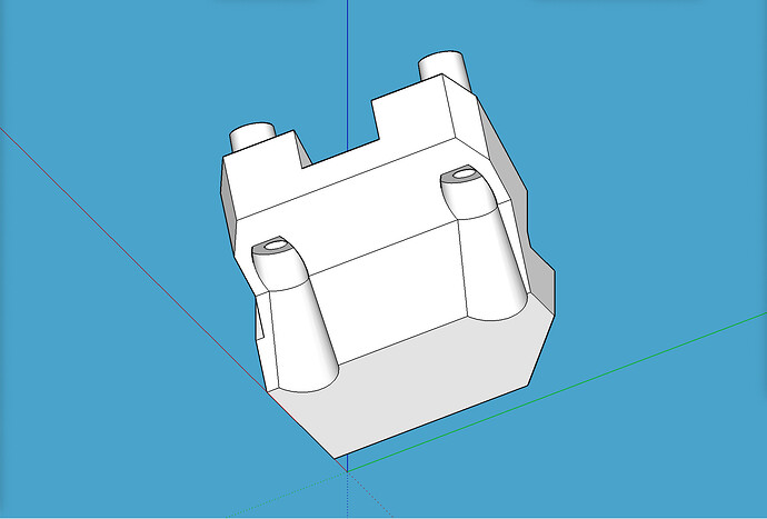
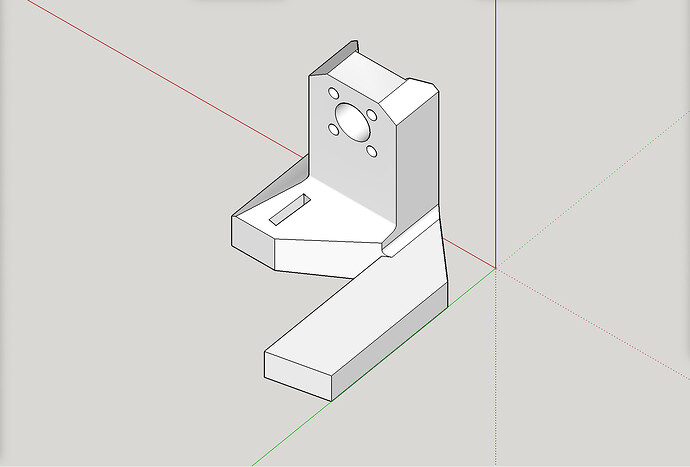
- I designed, printed, and installed a newly remixed “stub” on the right side of the old X axis (new Y axis, on the new Y-min side). The only change was to add a “stop” bar for the relocated X end stop (new Y end stop) to press against and trigger its switch. This stub is the part that the X belt (new Y belt) attaches to, and which also attaches to the lead screw on that side.
- In control box, I swapped the wires for X1 driver and Y1 driver with each other and re-labeled accordingly.
- In control box, I swapped the wires for X1 end stop and Y1 end stop with each other and re-labeled accordingly.
- In control box, I re-labeled the Y2 end stop as the new X2 end stop while leaving it plugged into the same pins, at E1 (on the SKR Pro 1.2).
Note: Some of what needed done could have been accomplished more than one way, such as firmware changes only, or physical rewiring only, and where I could, I chose to physically move wires and relabel them. This limited the number of needed firmware searching and edits.
If I am forgetting anything and you spot it, let me know and I will edit accordingly.
love this
thanks so much- you do quick work!
its looking like a decent amount of printed parts need swapped out. im going to keep my system stock until i have a few jobs on it, but keep this filed away for if i need to change my axis configuration
thanks so much
Basically one new printed part added (no disassembly required, but moving an end stop switch and rerouting its lead wires) and one new printed part swapped with old (some disassembly required). The disassembly there basically entails replacing one of the stubs, including detaching the “short belt” (formerly X belt, now new Y belt) from the old stub and reattaching it to new stub.
So at least you know pretty much what all is involved if you are considering doing it.
@Neilp
I added a download link for the firmware for swapping X & Y, on LowRider 3 with dual end stops.
- Firmware Download Link: http://design8studio.com/files/V1CNC_SkrPro_DualLR_2209-2.0.9.2-SWAP-X-Y-2022-06-21.zip
I printed the plates, so I’d need to figure out the ‘stubs’ mod. If it is simply to add a stop for the switch, maybe as simple as cutting a relief and epoxying in a piece of printed material or even a screw or something. Maybe I’m
Not visualizing it correctly.
So- you have this working? No ‘mirrored’ projects? You didn’t have to remap the coordinate system? Sounds like it was easier than expected overall
This (see download link below) should hopefully help you with understanding how simple the stud mod was!
https://www.printables.com/model/229940-lowrider-3-cnc-reversal-of-homing-on-short-axis-fo
Yes, it was as simple as adding on a “tab” for the end stop switch to touch for triggering.
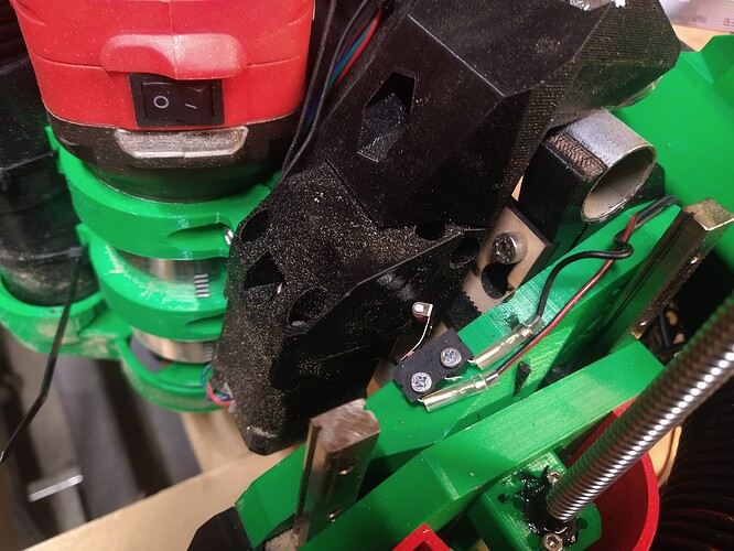
Here’s a pic of the modified stub. More pics below.
Why add it to the stub?
The stopping point for the switch to touch, has to be “part” of the whole assembly that raises and lowers with the beam itself. It’s likely unworkable to try to use the YZ plate’s flat side as the stop point, as you’d likely see the end stop switch get higher than the side plate itself while the beam is Z-homed to the top max, and then snap off your switch’s trigger finger when then moving back downward.
Here are some pics, including some of the modified stub:
Q. So- you have this working?
A. Yes. Working great. Exactly as expected.
Q. No ‘mirrored’ projects?
A. That’s correct. It works exactly as intended and expected, without any need for ‘mirroring’ projects.
Q. You didn’t have to remap the coordinate system?
A. That’s correct. No remapping of coordinate system needed.
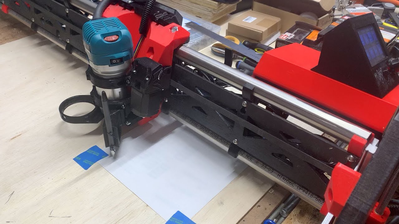
Check out a few seconds of video showing that no mirroring or other headaches are needed:
Yes, aside from the expected work to disassemble, move a part, replace a couple of parts, adjust some wiring at the main board, reassemble, and make the firmware edits documented above, it was pretty easy. The “fear of the unknown” and pushing to get things figured out is often more daunting than the project’s actual workload.
Dear @Neilp
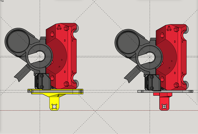
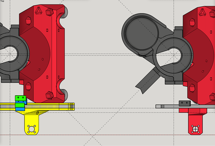
In considering that I have 3D modeling of my LowRider v3 in SketchUp, I realized I could import the “printed version” of the XZ plate into the mix and compare side-by-side to see what is up with a stub mod for this swap, in your case.
The printed XZ plate is 13.5mm thick, compared to milled plate’s 6.35mm thickness. However, some of the difference in the printed plate’s extra thickness is absorbed on the outside face of the plate, owing to its 4mm deep “pocketing” of insets for the bearing slides to attach. Thus, instead of having to deal with a 7.15mm difference, it gets reduced to dealing with a 3.15mm difference.
That 3.15mm difference ultimately means your LR Core has that amount of travel lessoned, when compared to a milled plate setup. To use printed plates, you make a tiny sacrifice of 3.15 mm on each side, for a total of 7.3mm less travel in the standard X axis, when compared to a LowRider v3 using milled plates.
This is illustrated in the screen shot below. The left side is with a printed XZ plate. The right side is with a milled plate. The gray on both sides represents a milled aluminum plate, 6.35mm thick, and the yellow on the left side, sticking out on both inside (up) and outside (down) illustrates the placement to accommodate the extra thickness.
However, the 6.35mm milled plate thickness / placement comes back into consideration whenever we turn our attention to the task of modeling a printable XZ plate that has a tab on it for triggering an end stop. Assuming one does not want to use supports to elevate the tab off the print bed to match the position of the tab on a milled plate setup (shown in BLUE in the next illustration), then leaving the tab resting on the print bed positions it 6.35mm away from the original spot (shown in GREEN in the illustration below). Note: the BLUE for tab and switch, was staggered slightly to the right to make it easier to distinguish from the GREEN for new placement of tab and switch. Also note: it’s easy to mistakenly think the difference should be 9.5mm (3.15mm + 6.35mm), but that would fail to take into account the slight loss of travel of the LR Core. I made that mistake while composing this post and had to edit to correct it.
This leads to an issue in which the end stop switch itself, shown in GREEN on the left for the new position), cannot be placed at the same elevation in the Z axis of the LR3 as the original remix, because that space is partially occupied by the LR Core.
Note: Based on real world measurements with calipers, which were a challenge due to limited access (and thus a little bit sloppy), I designed my new end stop switch mount to target placement of its edge 5mm shy of touching the new stop tab. The remainder of the distance was to be covered by the switch itself, as it has a slight protrusion from the mount, plus the trigger finger’s footprint when in its “contracted” / “touching” position. In real world results, that 5mm measurement turned out to be pretty much spot on, as it seems to be stopping right where I wanted it to.
The problem with the planned position of the end stop switch can be addressed in at least two ways: the switch could be raised up to clear the core, or it could be moved toward the plate (moved toward past the outside of the beam). The former approach requires a somewhat more significant remix of the new switch mount part, and extending the “tab” on the plate some more. The latter approach suffers the issue of supports to get the tab moved off the print bed.
I like to help. I’m willing to create a new remix that works for makers with printed XZ plates. The questions regarding that include:
- Is the goal to design for those who have not printed this plate yet (seems to be default approach to help the most makers), or to help those who already printed their plates (which would help you) or both?
- Which approach to take (regarding the above two ways of getting the switch repositioned? (Seems that saving from having to print supports is the better approach.)
All that having been said, your idea about gluing on (with epoxy) an add-on tab, or screwing one on, or both, is perhaps a decent approach. If you decide that route seems desirable, I can help by use of my modeling.
UPDATE
Don’t feel any pressure to use these if you don’t choose to. I modeled up a remix just for those who either have printed, or will be printing, their XZ plates.
LowRider 3 CNC - reversal of homing on short axis (for swapping X & Y axes) FOR PRINTED XZ PLATES (v1.3b)
https://www.printables.com/model/230531-lowrider-3-cnc-reversal-of-homing-on-short-axis-fo
Here are some details and pics:
This remix seeks to accommodate owners (or potential makers) of a LowRider v3 MPCNC who either have printed, or plan to print, their XZ plates (as opposed to buying or making milled metal XZ plates) and who also desire to flip the homing direction of the short axis, which by default is called X, as they also seek to swap the X and Y axes of the CNC machine, as documented and explained here. If you don’t want to reverse your short axis homing, you don’t need this. If you want to swap your X & Y axes, you probably need to reverse your short axis homing, and this should work for that.
Full disclosure: I did this with milled XY plates, not printed. I made this remix not for myself, but for others. Accordingly, until someone tries this with printed plates, and succeeds, I cannot properly guarantee it has no issues. If you make it, post your make and alert me to any issues.
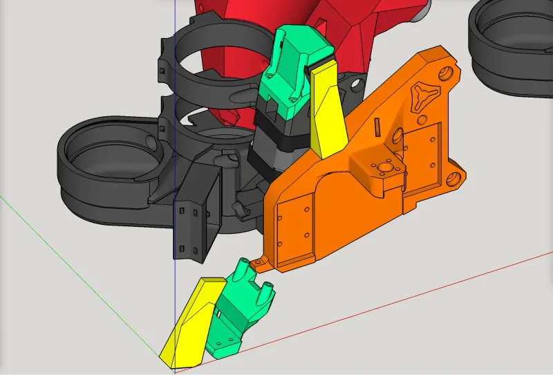
In the illustrations below, obviously the colorations are only for identification purposes.
For makers who have already 3D-printed their XZ-plate-right
Makers who have already 3D-printed their XZ-plate-right can print a stand-alone addon tab and glue it onto their existing XZ plate. This addon tab serves as the end stop surface for their (relocated) end stop switch to touch for triggering. These makers should print the part highlighted in yellow ( “addon-stop-tab-for-printed-XZ-plate-right-v1.3b.stl” ) and epoxy it onto their existing XZ plate as shown below ( plate shown in orange ). They also should should print the part highlighted in green ( “X end stop mount (for reversal of homing) (for printed XZ plate) v1.3b.stl” ), attach the end stop switch to it, and install it onto their existing X motor mount as shown below. This involves removing the two front screws holding the motor to the mount, which are short M3 screws, and replacing them with two M3 x 30mm screws that go through the new end stop switch mount, through the existing motor mount, and into the stepper motor.
These parts can be printed in PLA, with 30% infill and 3-4 perimeter walls.
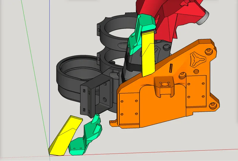
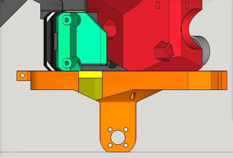
For makers who have yet to 3D-print their XZ-plate-right
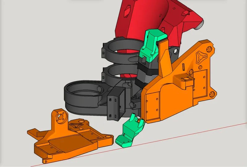
Makers who have not yet 3D-printed their XZ-plate-right can print the REMIXED XZ-plate-right ( shown in orange ) that has a pre-attached addon tab to serve as the end stop surface for their (relocated) end stop switch to touch for triggering. These makers should print the part highlighted in orange ( “REMIXED_printed_xz-plate-right_with-addon-tab-for-reversal-of-homing.stl” ) and use it as their XZ-plate-right as shown below. They also should should print the part highlighted in green ( “X end stop mount (for reversal of homing) (for printed XZ plate) v1.3b.stl” ), attach the end stop switch to it, and install it onto their existing X motor mount as shown below. This involves removing the two front screws holding the motor to the mount, which are short M3 screws, and replacing them with two M3 x 30mm screws that go through the new end stop switch mount, through the existing motor mount, and into the stepper motor.
These parts can be printed in PLA, with 3-4 perimeter walls. The remixed XZ plate should be printed with 70% infill, while the end stop switch mount can be printed with 30% infill.
Thank you for this, it really helped a lot! I wanted to share a simple work around for people with printed plates. I just attached the micro switch to the plate
Hey cool workaround!
