This (see download link below) should hopefully help you with understanding how simple the stud mod was!
https://www.printables.com/model/229940-lowrider-3-cnc-reversal-of-homing-on-short-axis-fo
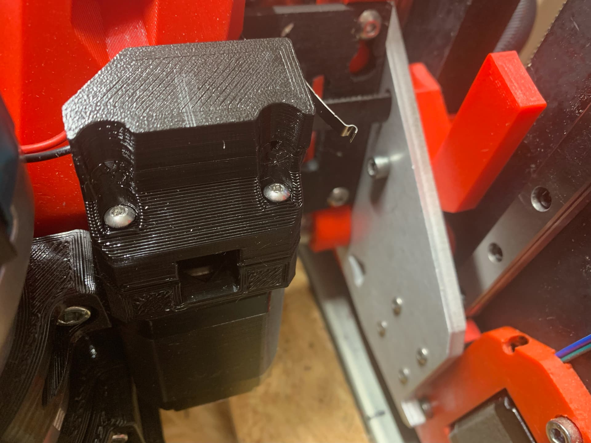
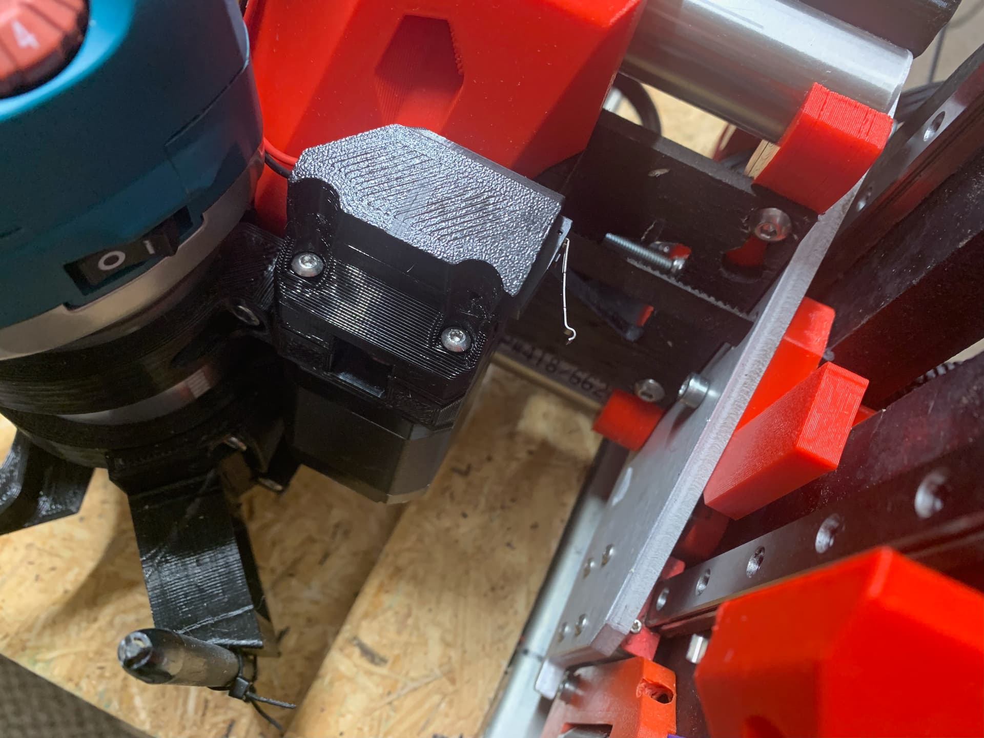
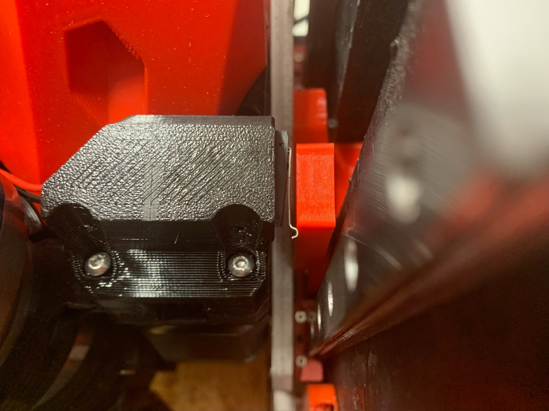
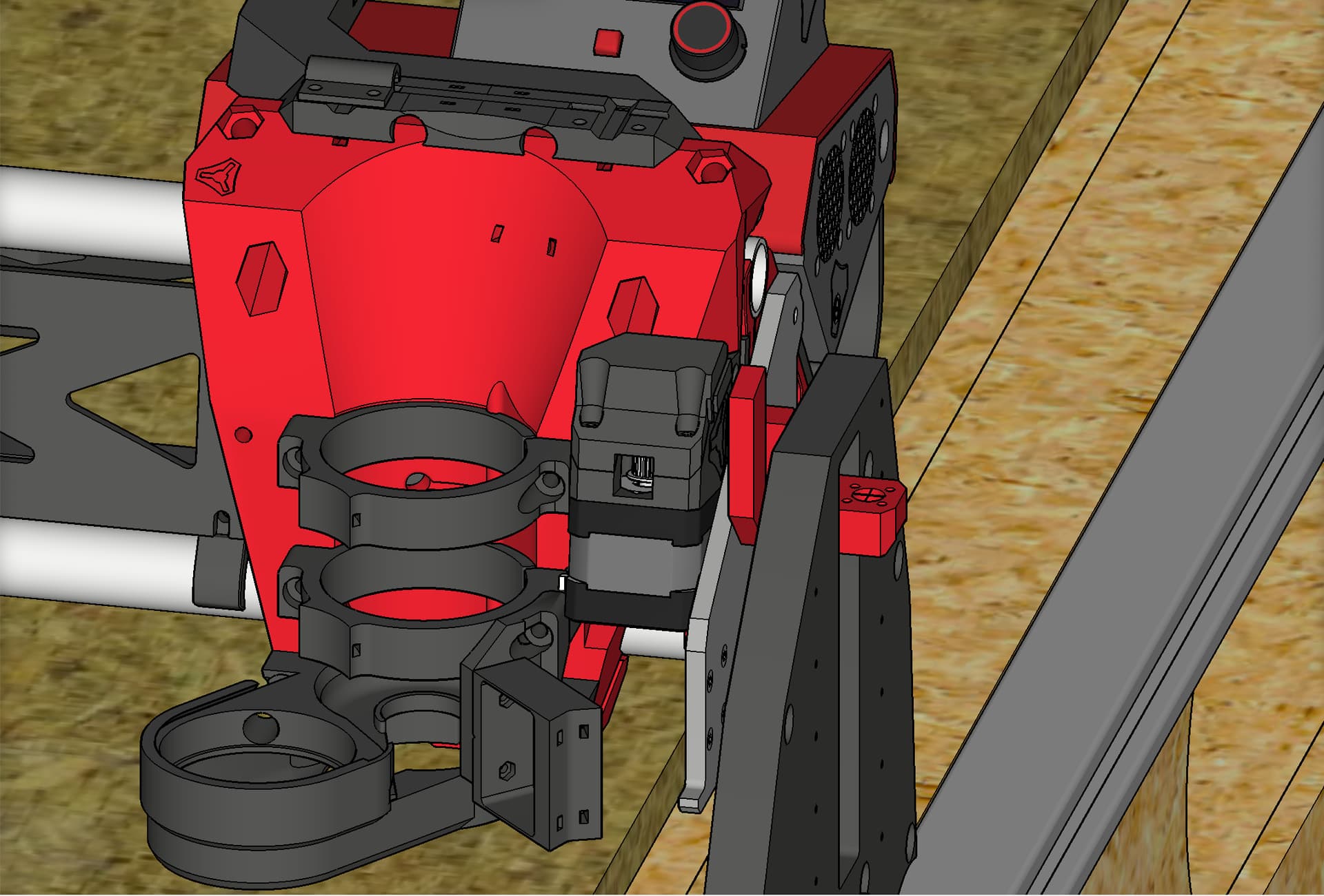
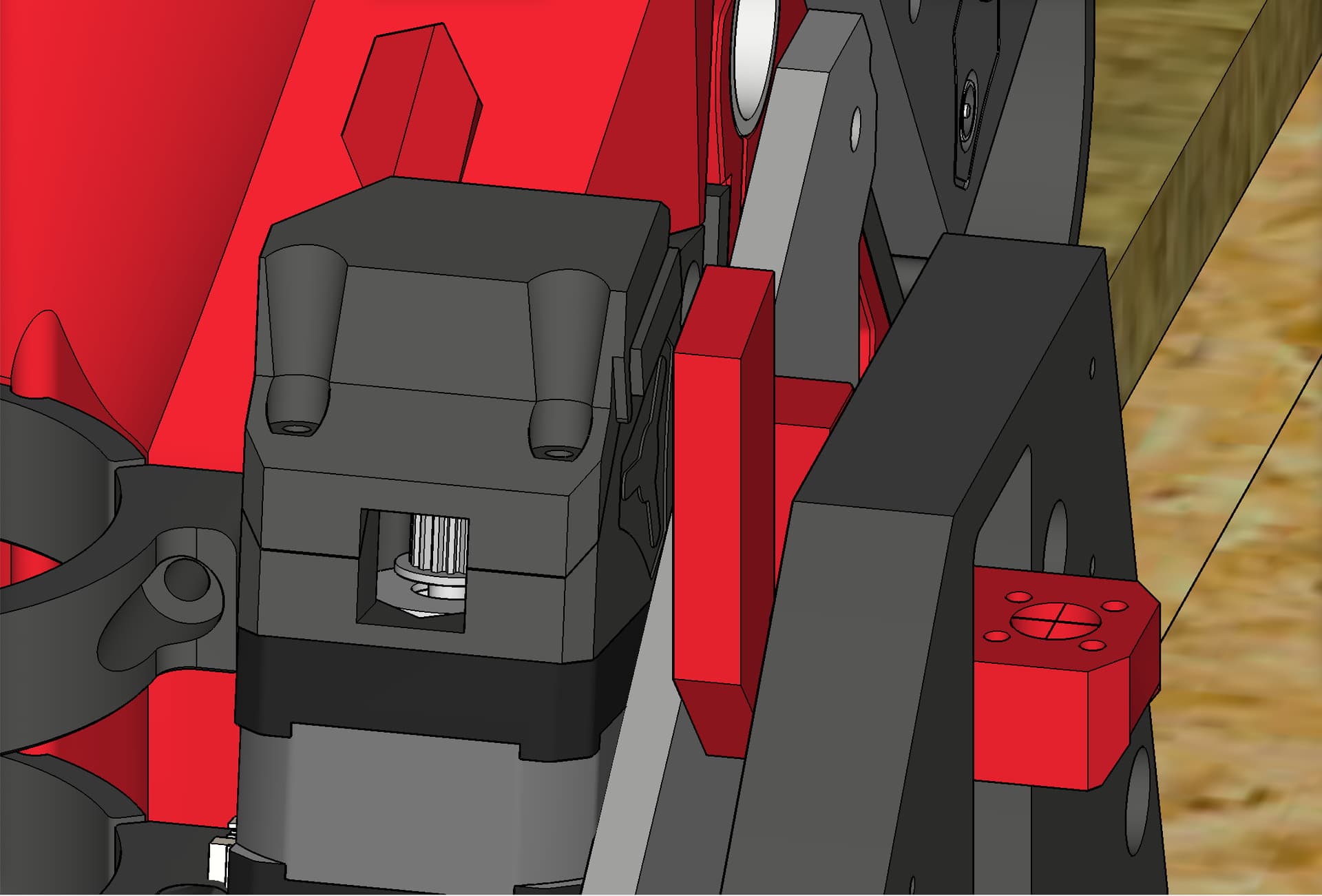
Yes, it was as simple as adding on a “tab” for the end stop switch to touch for triggering.
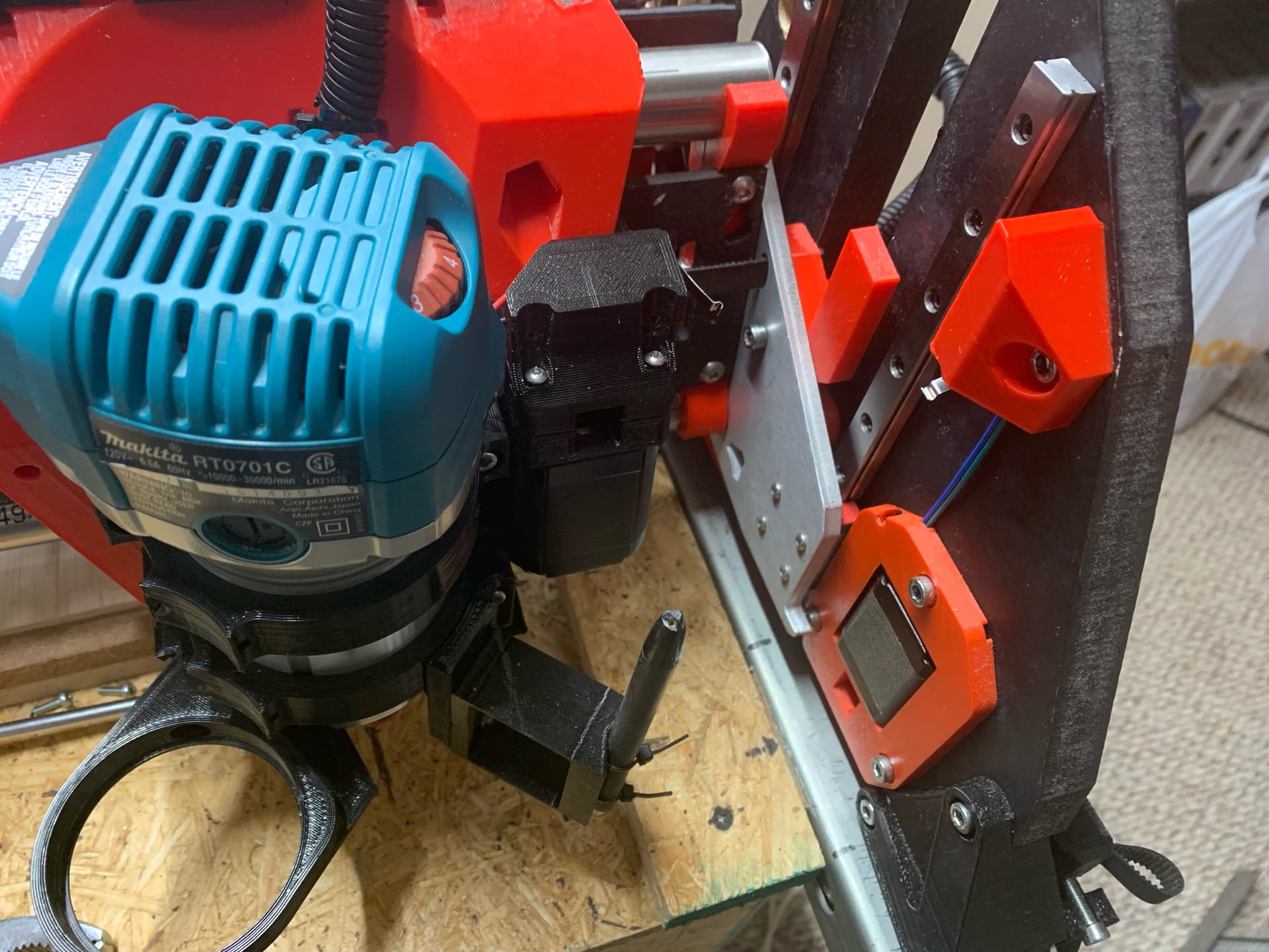
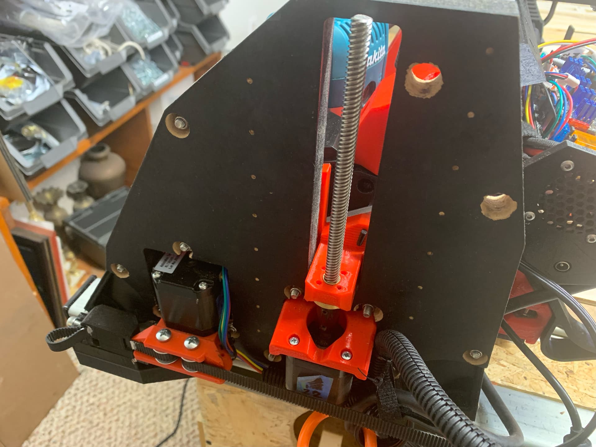
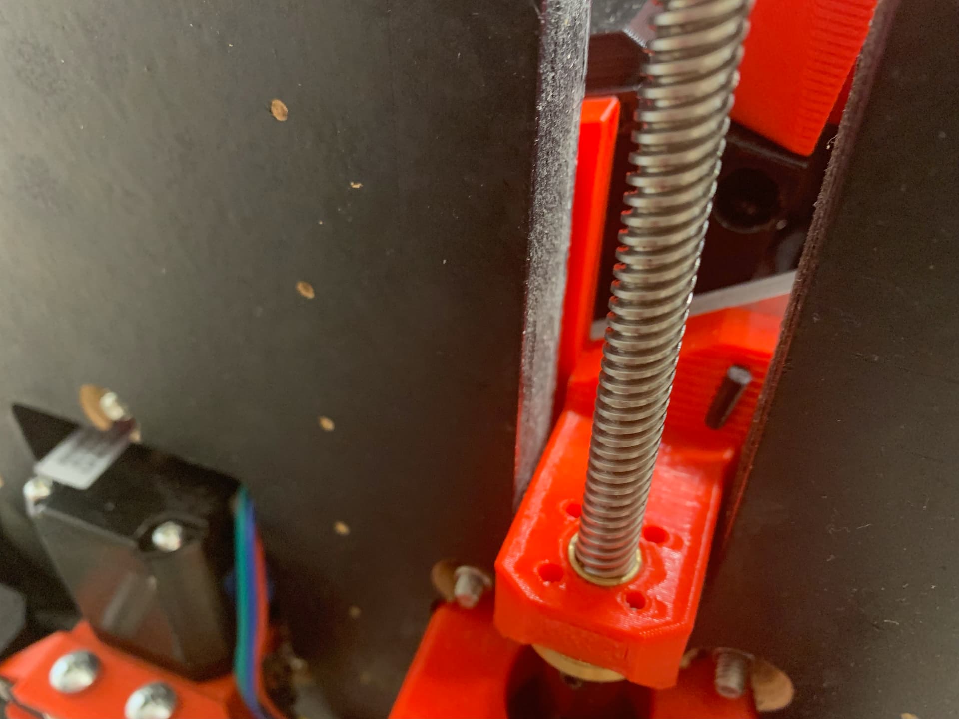
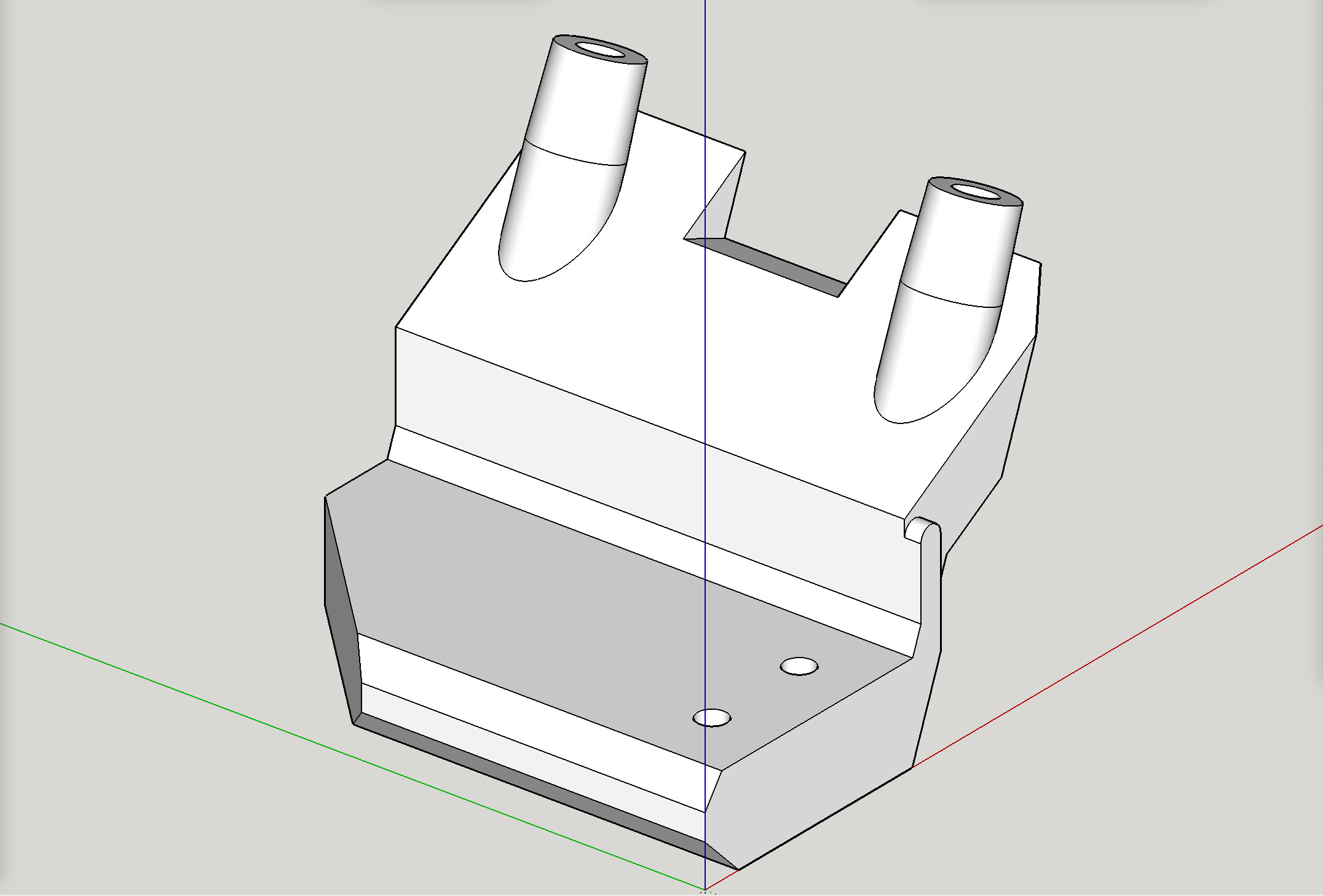
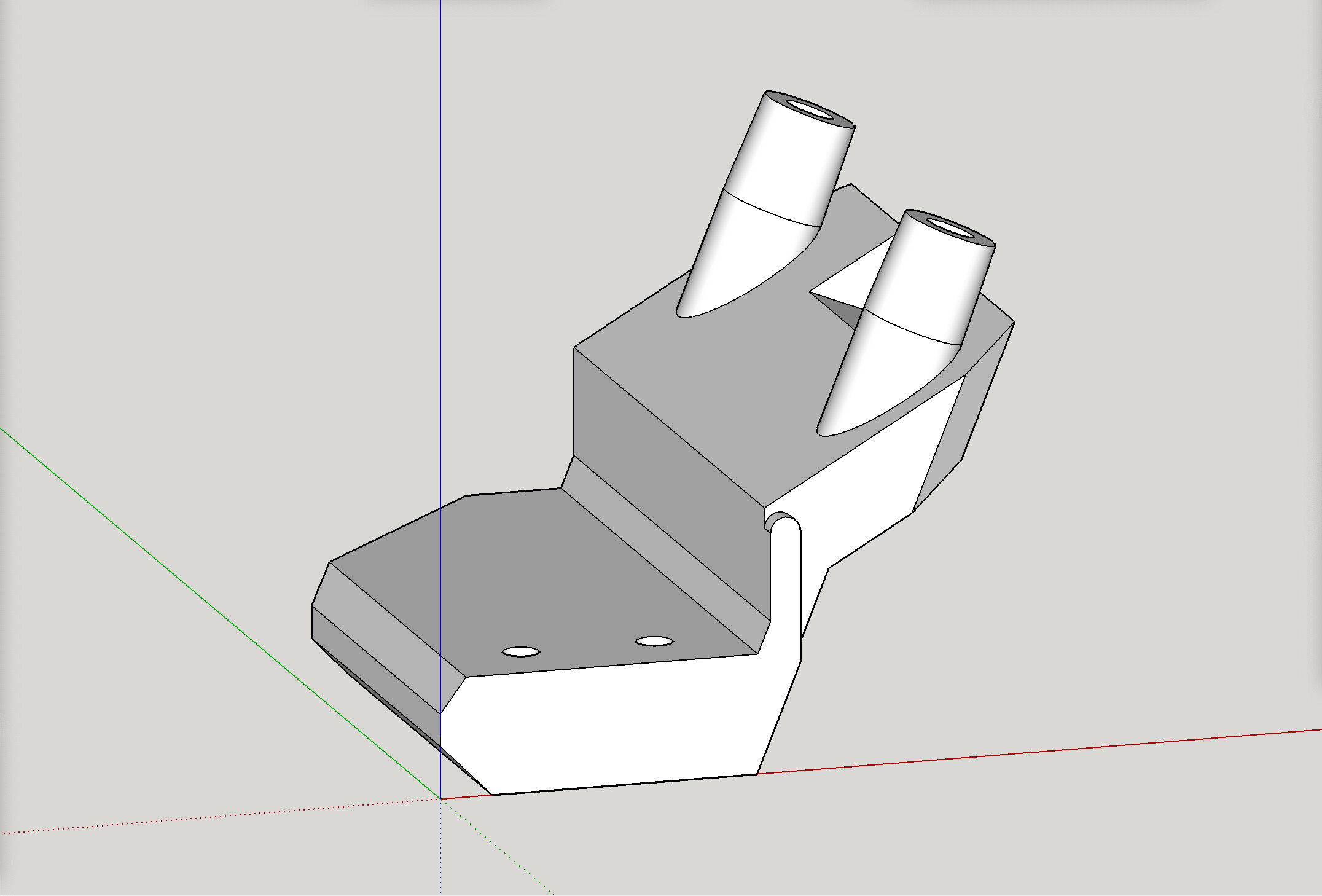
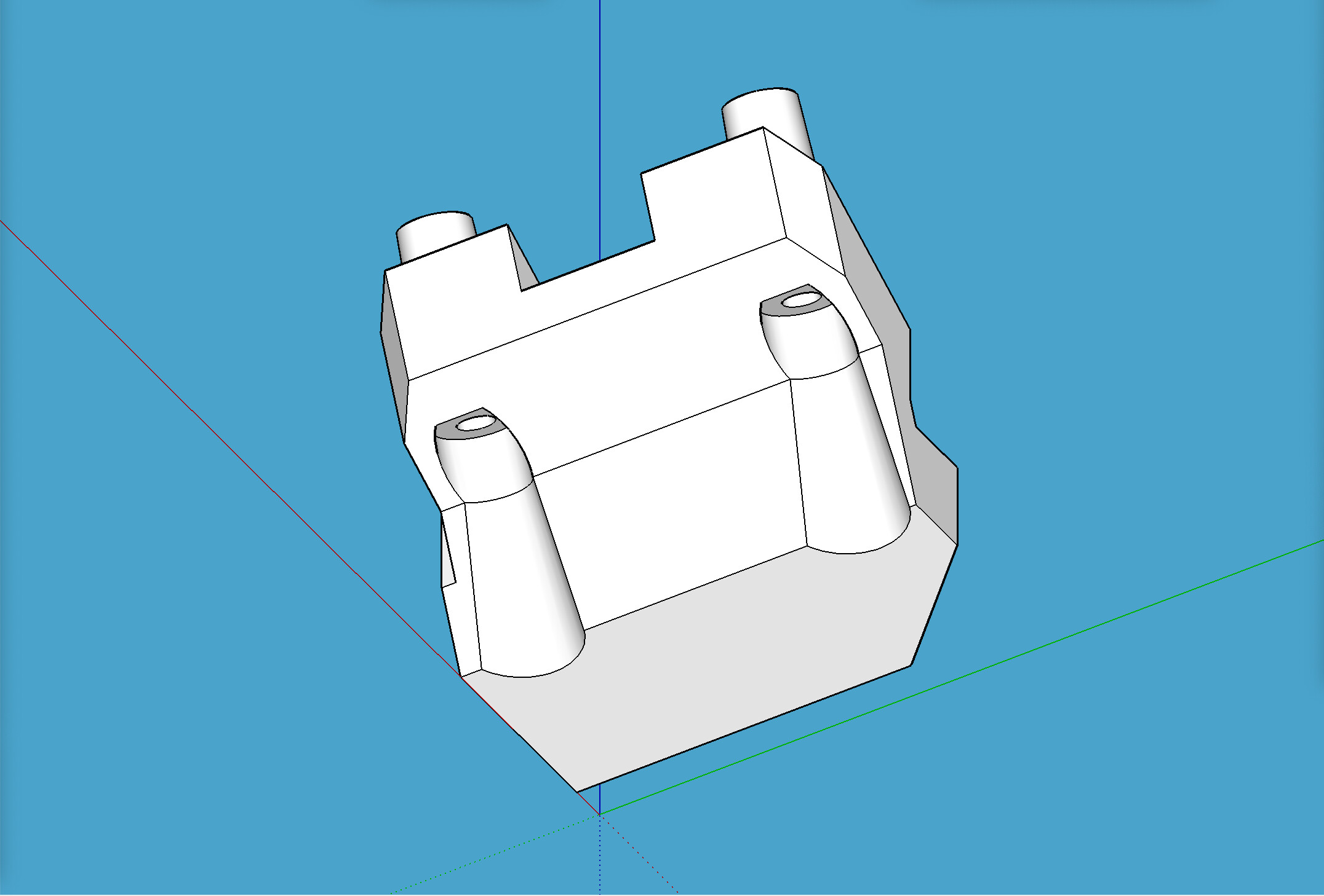
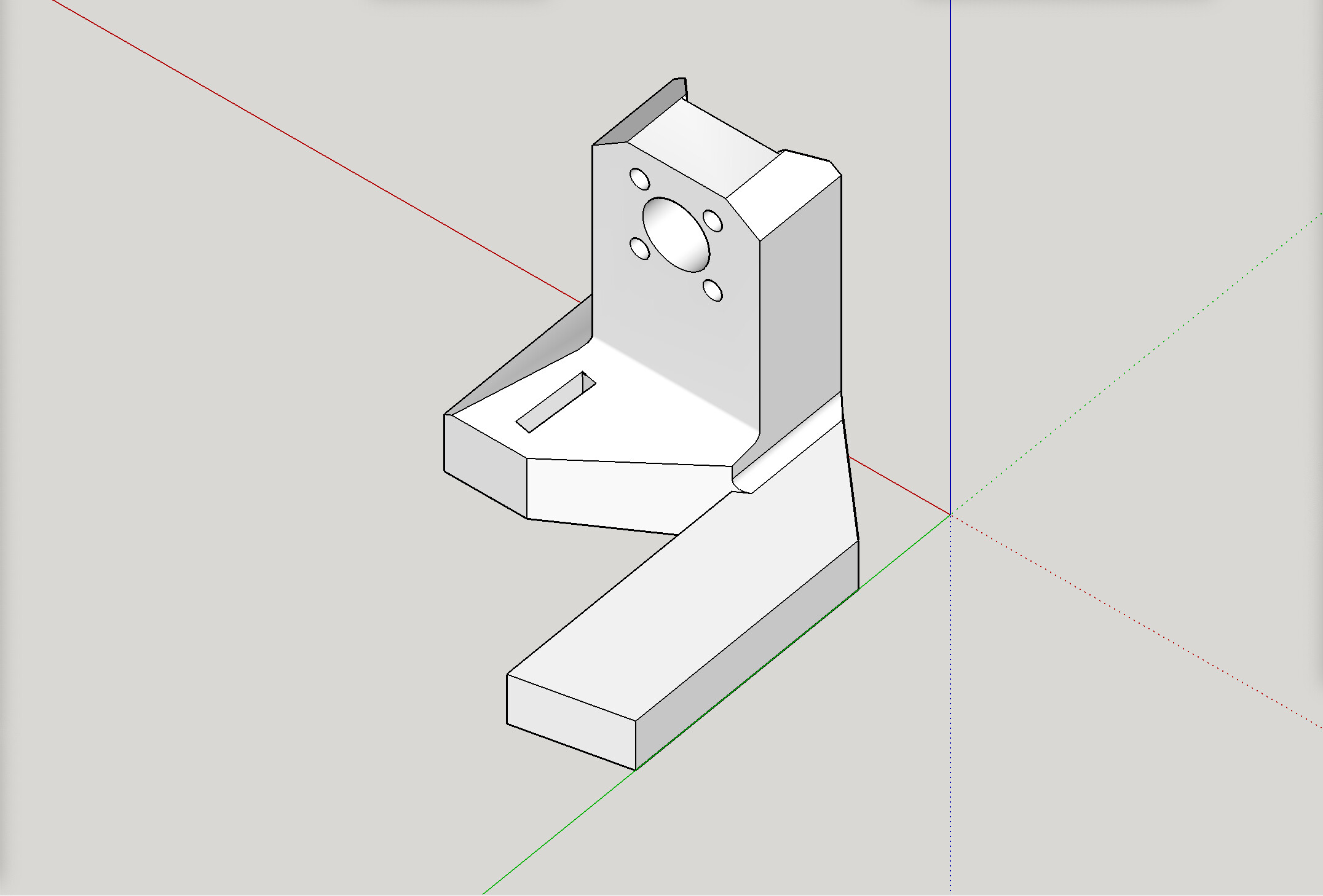
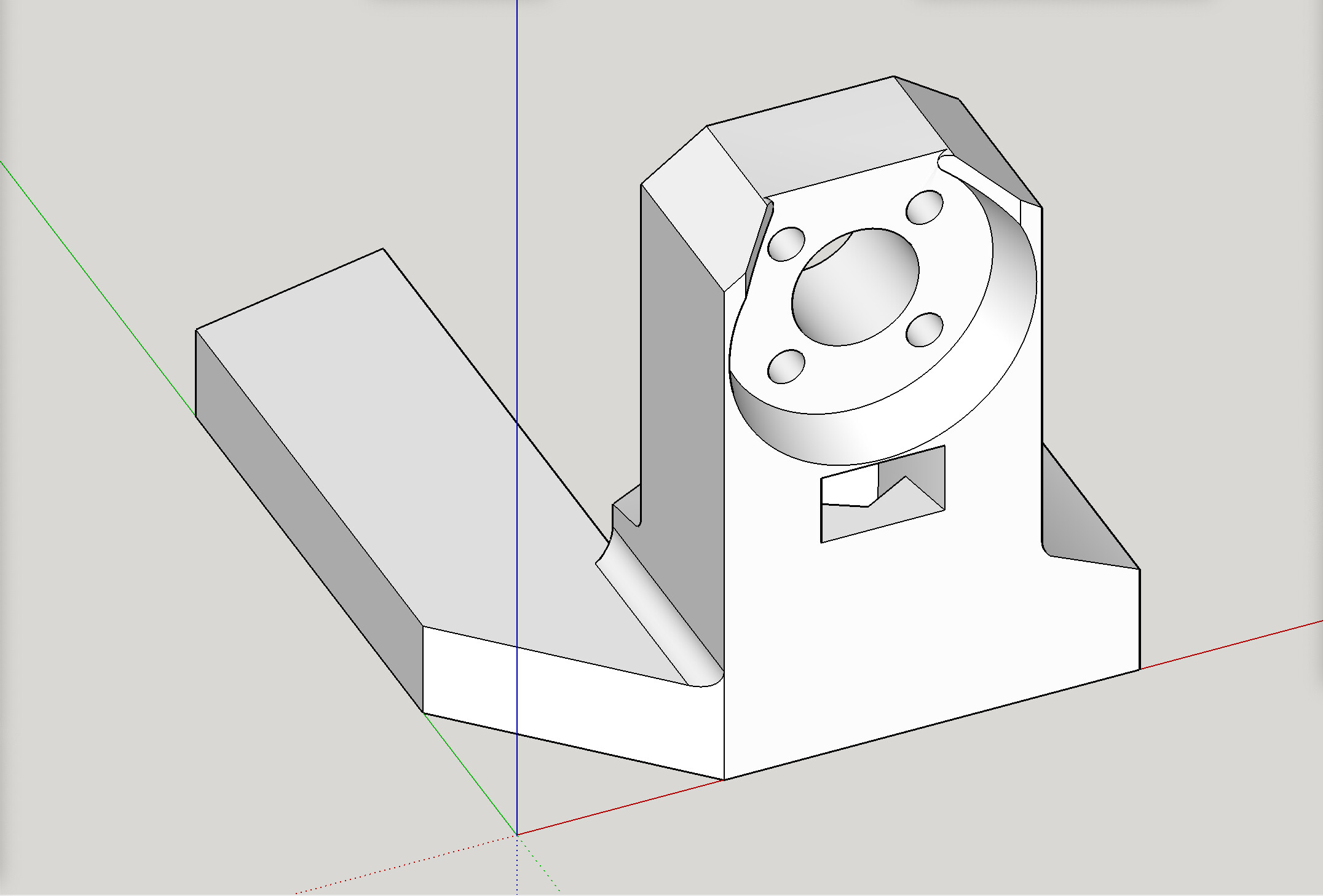
Here’s a pic of the modified stub. More pics below.
Why add it to the stub?
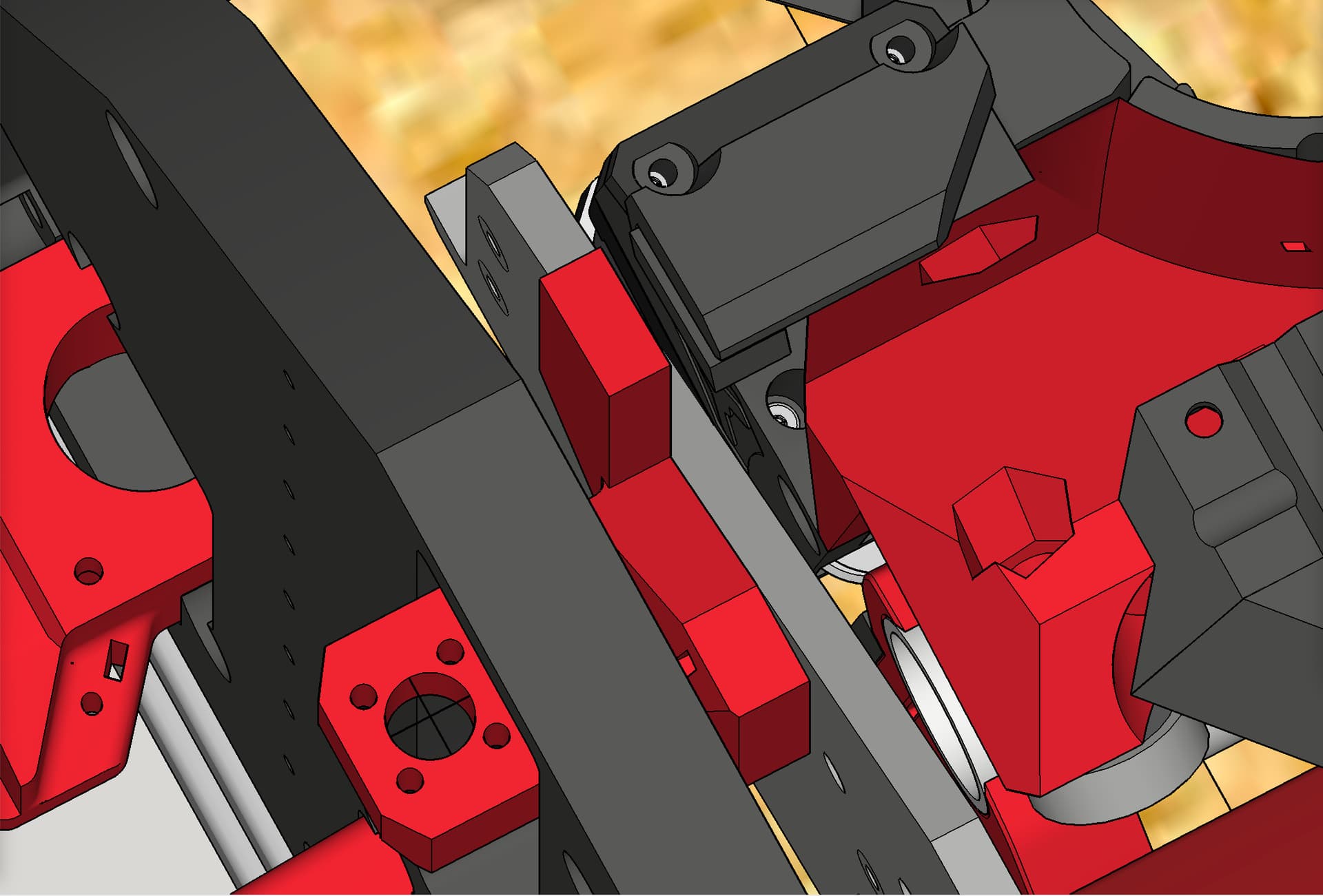
The stopping point for the switch to touch, has to be “part” of the whole assembly that raises and lowers with the beam itself. It’s likely unworkable to try to use the YZ plate’s flat side as the stop point, as you’d likely see the end stop switch get higher than the side plate itself while the beam is Z-homed to the top max, and then snap off your switch’s trigger finger when then moving back downward.
Here are some pics, including some of the modified stub: