Sucker for punishment laser build

So my CoreXY laser is dead. RIP.

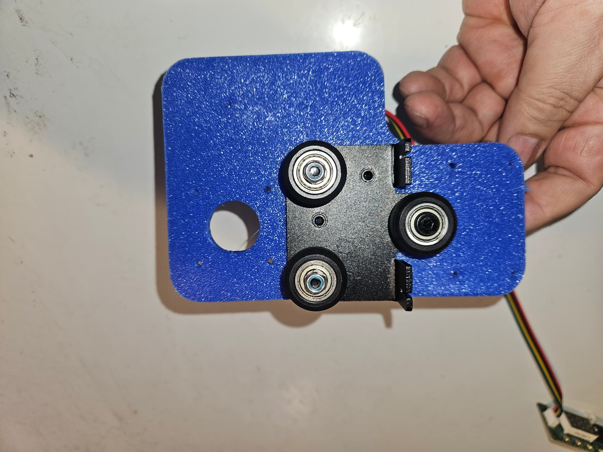
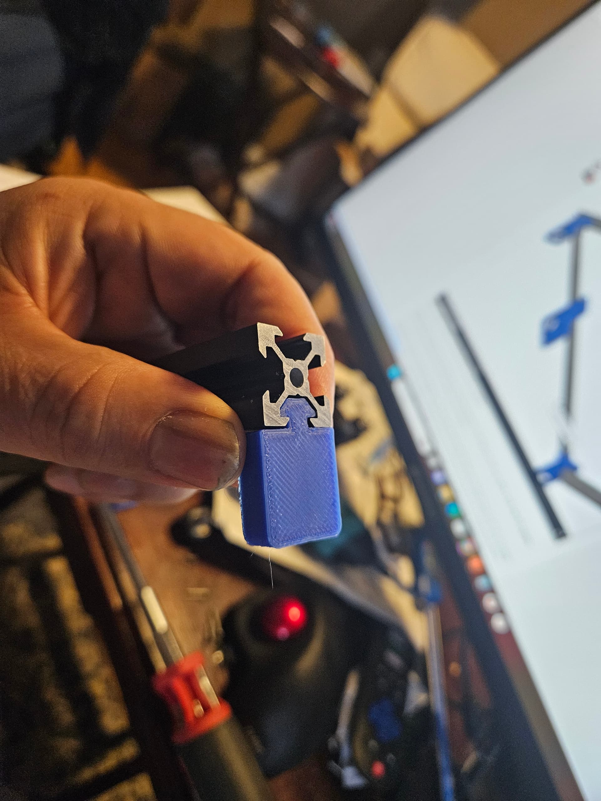
When I started on the MP3DPv4 I bought a bunch of 2020 V slot and 2040V slot, as well as many misc items that work with it. I was quite interested in the V slot and the various wheeled thingamabobs that use it. I expected the same mini wheels that the ZenXY and MP3DPv3 use, but these are bigger, so I didn’t get to use them as I expected. I bought several of the 3/4 wheel V slot gantry plates, and a couple of the Ender 3 style hotend sliders, as well as a few other styles, but (so far) those don’t seem relevant.

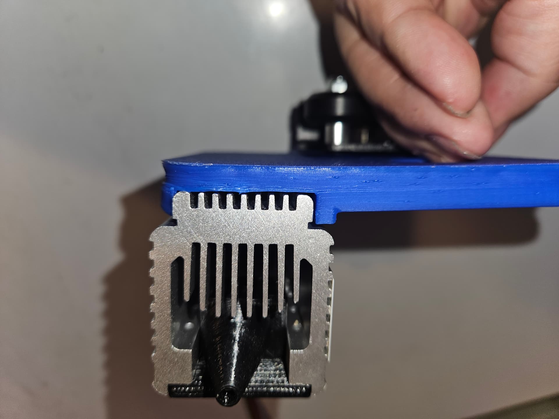
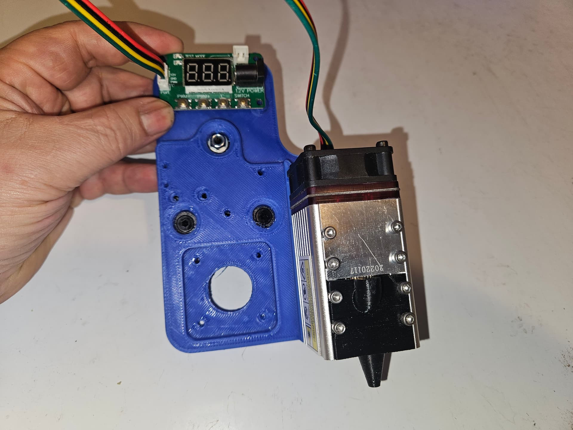
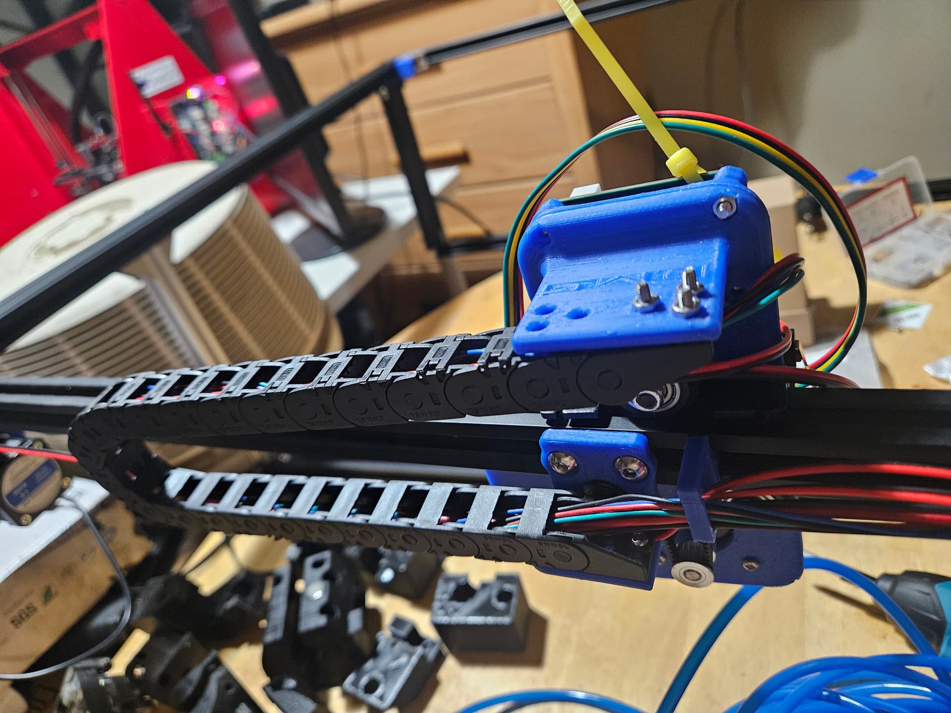
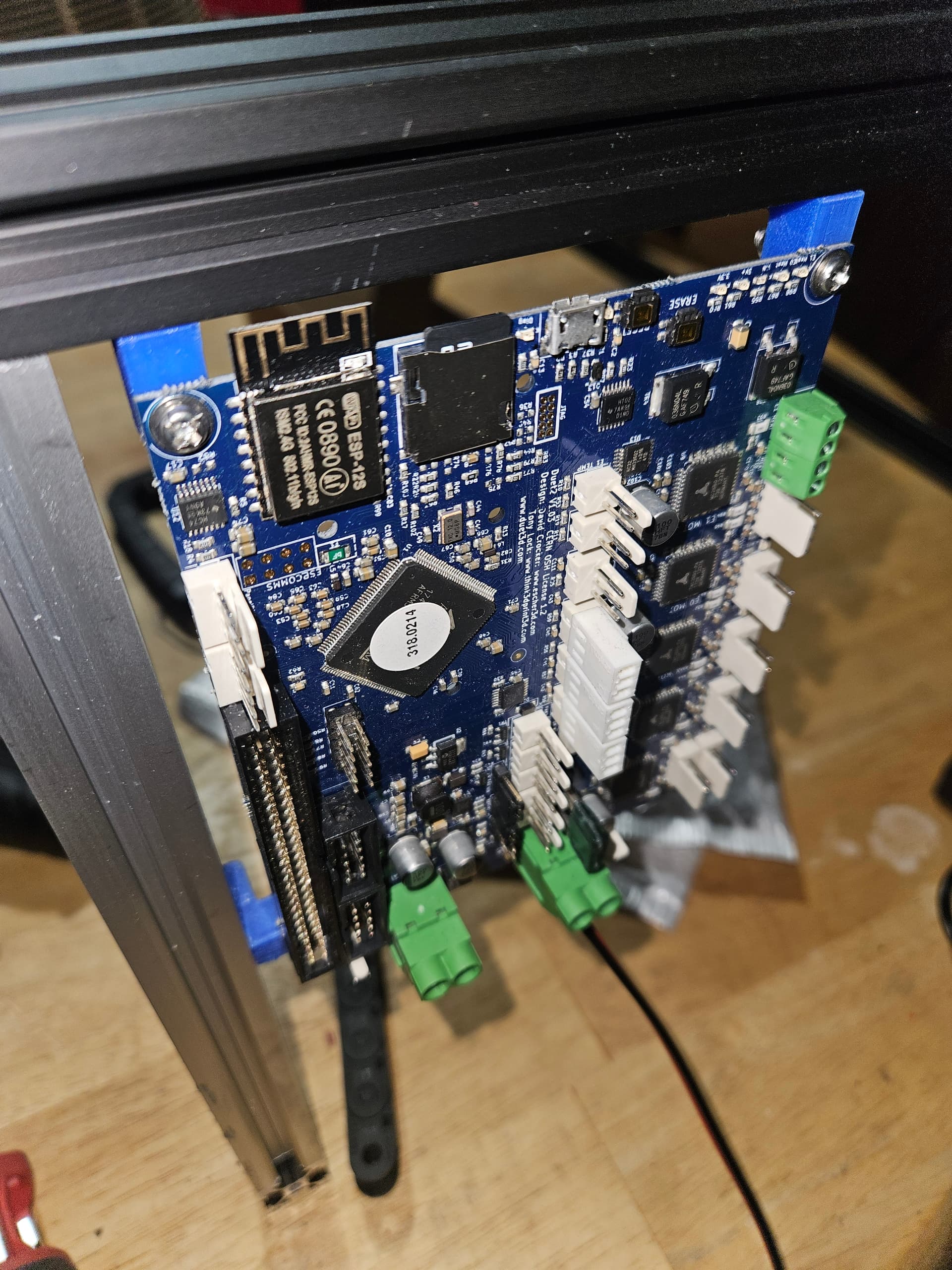
So I have 2 of these NEJE 40W (10W optical) laser modules, several NEMA17 motors and more control boards than I can shake a stick at. (And I’m a fair hand at stick-shaking, if I do say so myself. :rofl:)

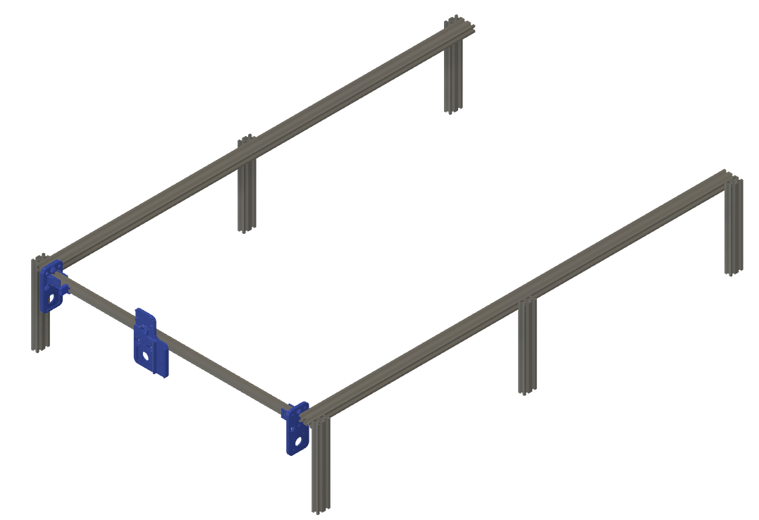
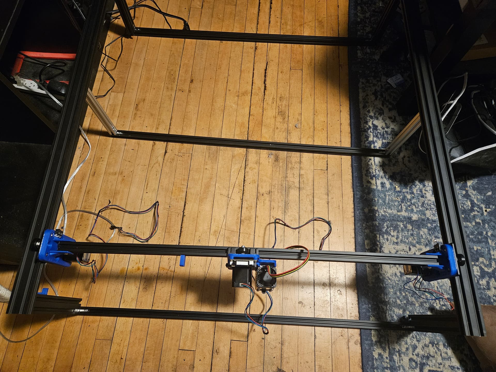
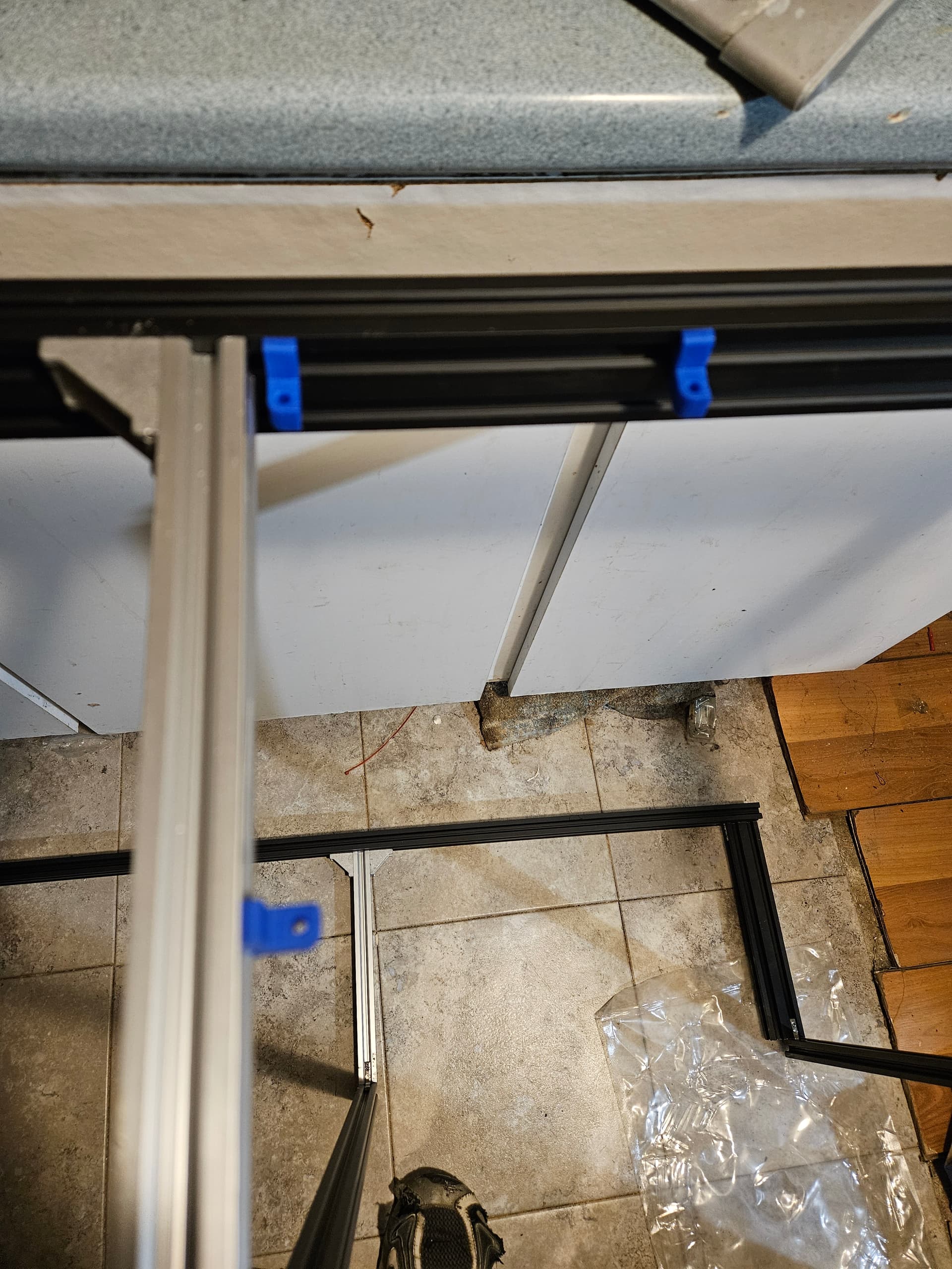
So the idea will be the basic extrusion frame box. A floor made from 1/32" steel sheet, because. I want it to manage 20" by 30" .aterial at a minimum, and if I can swing it, 24" by 48". I have 2m pieces of V slot, so I think it’s doable.

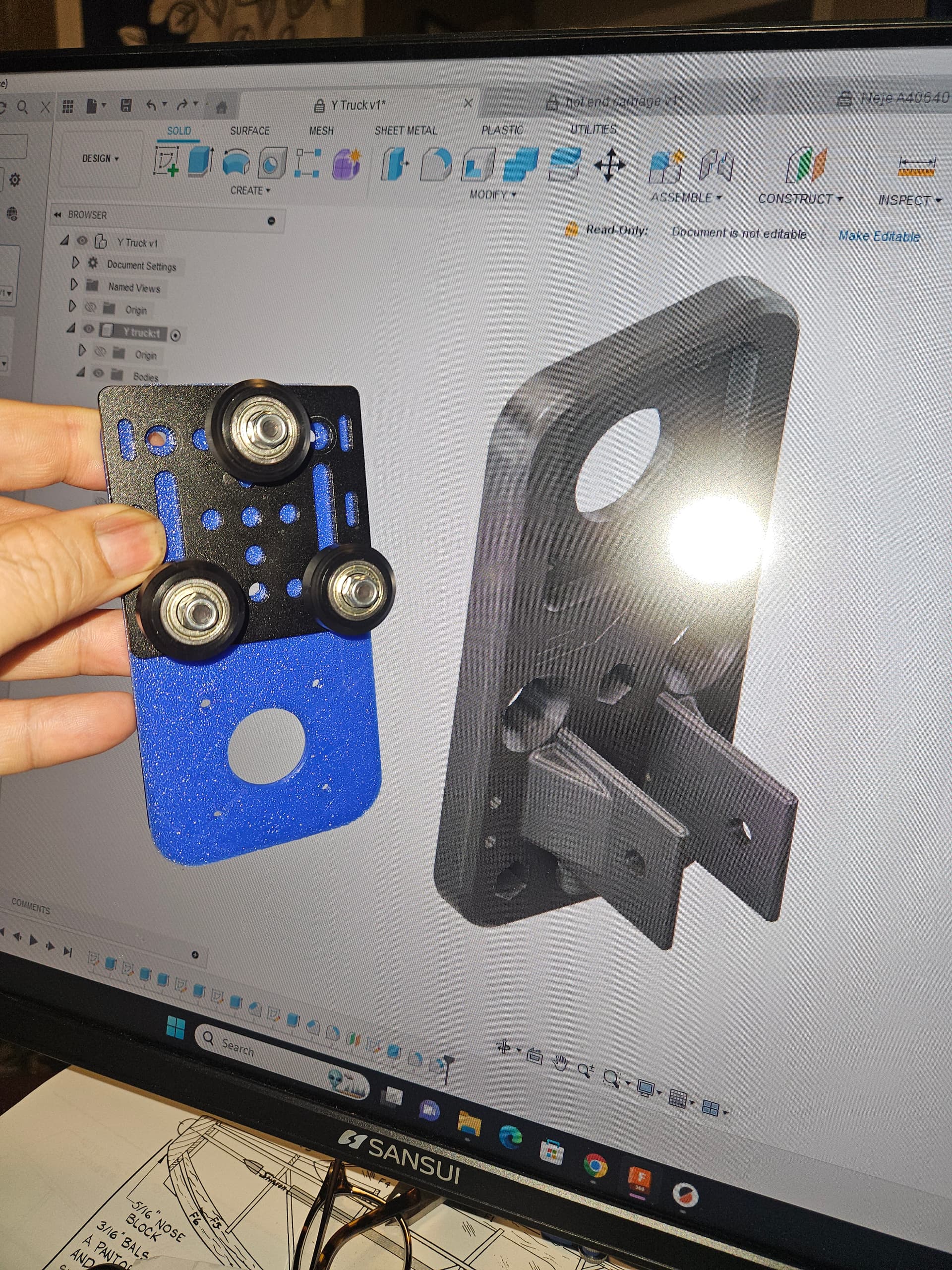
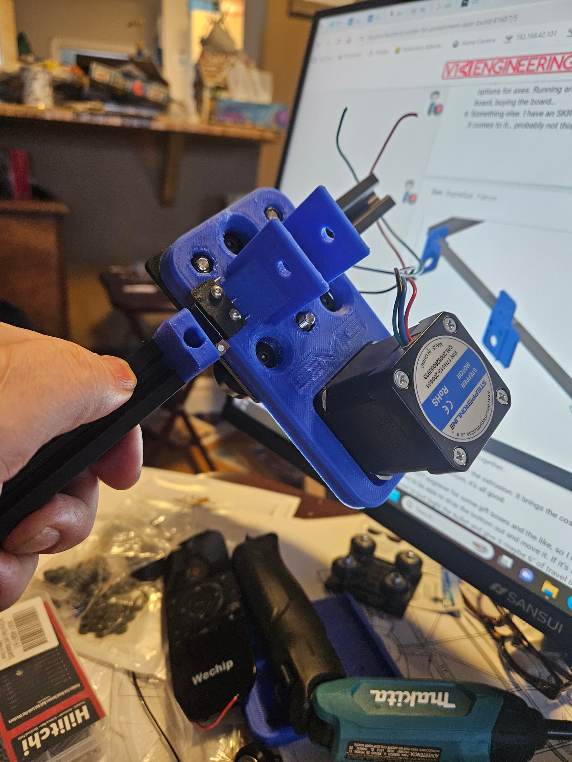
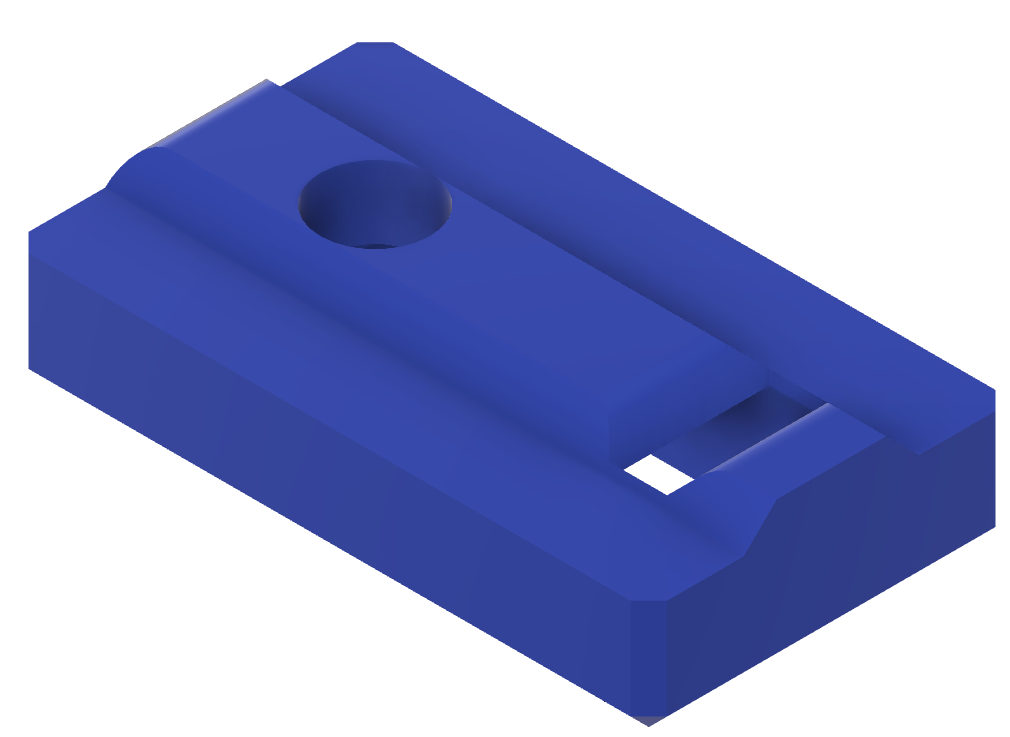
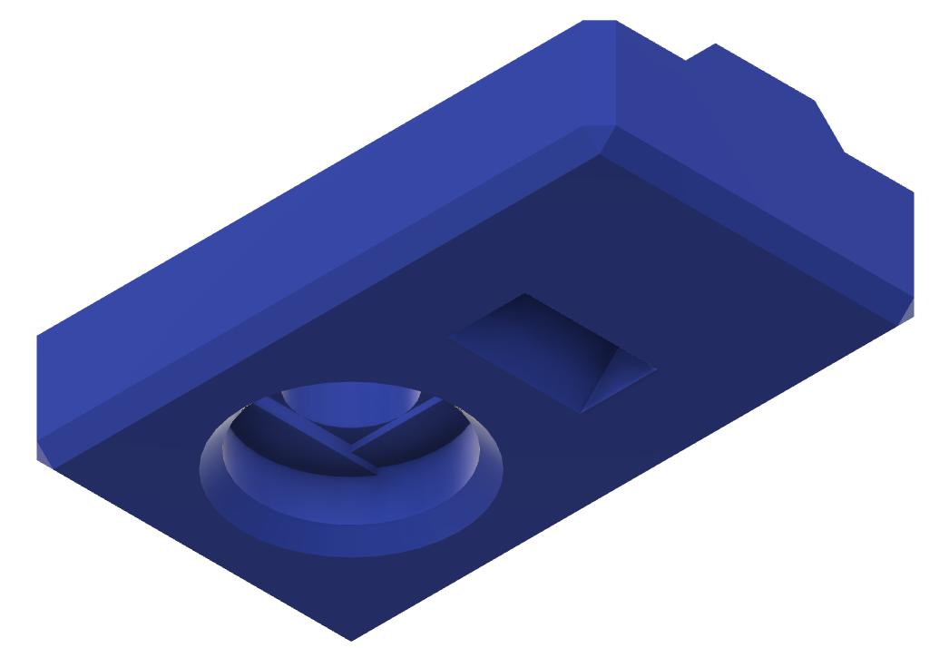
The wheel gantries sure do cut down on the complexity of the 3D printed pieces, and the cam offset wheel axles take care of adjustment nicely. I have a rough draft of trucks and a core thst should work.

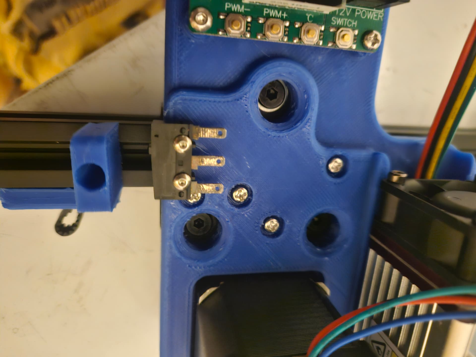
The plan is to make 2040 rails for the long Y axis, and use dual Y motors, one on each truck. I also will make an allowance for dual endstops, because why not?

The rough draft has no provision for a Z axis on the gantry, but maybe I can rig something for the floor of the laser… it could even be entirely manual, I think.

I also want to be able to use a rotary axis, which is my one and only reason for not going CoreXY on this version.

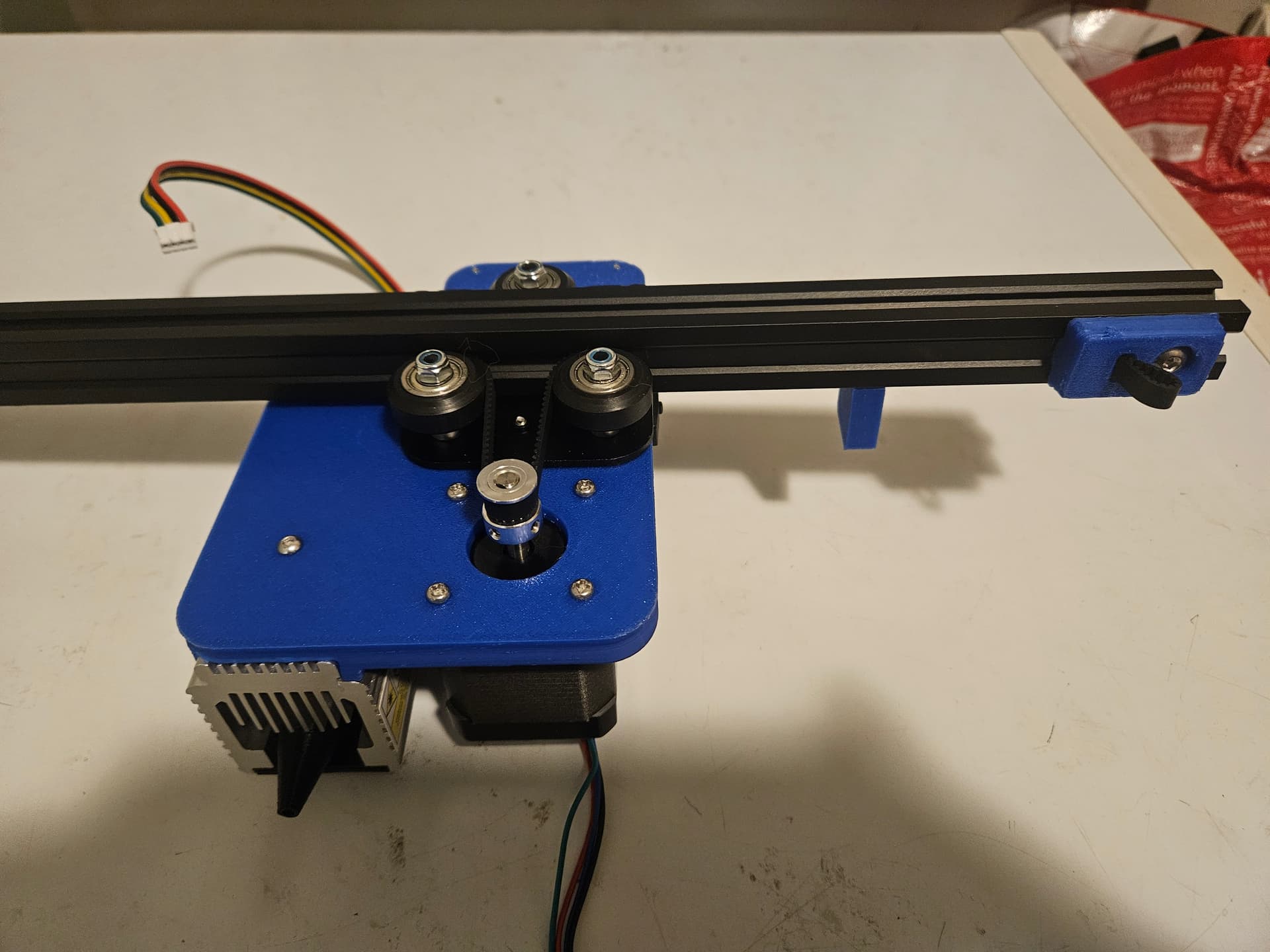
I had an idea for the belt drive. If the belt is in the V slot (only 6mm belts work for this) I can use the wheels as idlers to pull the belt around the drive pulley. I dismissed the idea, but I kind of liked it. Turns out that Openbuilds does the same thing for some of their gantry builds, and I’m using some of the same gantry pieces, so I ran with it.

One thing that never seems to get addressed with the NEJE laser mounts is the control board, so I have a provision for that, too.

Well, going to fire up the printer and try these rough draft pieces.

1 Like

Ugh….i was all excited until I read the whole thing and CO2 didn’t appear anywhere inside….

But I’ll follow along intently anyway :grin:

Well…

This version will run a NEJE diode laser. The plan with the extrusion was for a CO2 laser, but that’s still a bit coming, and Imfound.myself.in.need.of a new diode machine much sooner than anticipated. I have plenty more parts, and modifying the carriage for a CO2 laser head is easy (in fact this version is a midification of the one originally specced for the CO2 head.) The Y trucks are a redesign, the original was.much more paranoid about losing square should I have a Y motor skip steps, so that one good motor would rather drag a dead motor than go more than about 3mm out of square. This one is less rigid, should be more forgiving at the build stage.


Test fit of the NEJE heat sink


Placement of the temperature feedback control board. 2 small holes near my pinky finger are for X axis end stop switch support.


Ender style V slot carriage on the back.

Edit: that’s a super tight fit, so I may make the openings for the 2 little prongs 1mm bigger.

3 Likes

In the planning is a drag chain anchor for the carriage, though I strongly suspect that what I’ll end up with is a zip tie. Maybe a clip to the X motor, in which case I can re-use the drag chain anchors I designed for the MP3DPV4. Maybe.


This has the X gantry coming out in line with the Y rails. The disadvantage is losing an extra 20mm of rail movement, but given that the laser head is 100mm wide, that’s minor, I think.

In the CAD drawing, you can see the provisions for the Y endstops next to the gantry clips.

2 Likes

Now to decide on electronics…

Options:

  1. Re-use the Bart Dring 2209 pen/laser board. Pros are that I already own it, so free(ish). The 2209 drivers are very good. It.is a good use for hardware that I own. Cons: I would need to run the Y axis in series mode, and no dual end stop squaring. A axis would require me to unplug one axis from the machine.
  2. Use one of the spare Duet Wifi boards that I have around. Somehow I have ended up with 2 spares. Pros are that I already own it again. I am very familiar with RRF, and have just finished going throughnall of the necessary config with the LR3. Dual end stops aren’t a problem, and I can use a quick macro to move to a specific location for rotary, redefine the axes so that X and Y work the rotary making CAM easy, while still maintaining holding torque. On the unused axis, limiting accidental movement. Cons are that RRF isn’t particularly well supported by LightBurn. Also the Duet Wifi needs an add-on (which I have several of) in order to supply the PWM signal for a laser.
  3. Jackpot time. Pros are that it’s a jackpot. :rofl: :joy: :eyes: well, FluidNC and 6 drivers mean plenty of options for axes. Running an A axis should certainly be easy enough. Cons are waiting for the board, buying the board…
  4. Something else. I have an SKR Pro 1.2 here, an MKS Gen L, and more than a few RAMPS stacks, if it comes to it… probably not this way…
1 Like


Super quick 'n dirty concept of how it goes together.

I figure that I’ll make a box structure out of the extrusion. It brings the cost up quite a lot, but if it gives me a secure foundation for a steel bottom, it’s all good.

I have been using my CoreXY engraver for some gift boxes and the like, so I might need 3-4" of Z to keep doing that, or else I need to be able to drop the bottom out and move it. If it’s a 2’ by 4’ work area, that’s going to be a pain. easier to just bite the bullet and give it maybe 6" of travel in Z now. Maybe use expanded sheet metal as a second layer and just have various sized shims to raise or lower the expanded sheet pieces. That should serve to allow me to put in the small boxes that I sometimes engrave on, and raise the material for thin sheet pieces for cutting or engraving.

1 Like


Small progress. Stop blocks. They take an M3×10 screw to fasten to the extrusion, so they are adjustable for setting the zero point.

Edit: oh, and the carriage is now on revision 2, the bits holding the laser weren’t quite enough, so I added a bit more meat to the clamping bits (0.25mm) and cleaned up the reliefs for the mounting screws. I reduced the diameter for the holes for the limit switch, a smidge as well, they were just a little loose. The result seems much improved, but I think I will add room for a nut in the clamping mechanism, as I stripped out the screw in the plastic to clamp the laser in place. (Probably still good enough to hold)

4 Likes

Looks like a fun project! Watching with Interest…

Curious what motion and focus accuracy you’re designing/shooting for? Using 1.8deg or 0.9deg steppers, or doing anything else for higher resolution.

2 Likes


so a few more parts drawn up. (Hard to see in that render.)

End stop blocks. These basically fit into the V slot and hit the triggers on the stop switches. The original idea was that they would hit V slot fitted at right angles to the direction of travel, (And they could. I made sure that the wheel trigger would hit one side, and even if the lever/wheel were removed, the actual switch pin would hit the other side.)

Belt tuggers. Man these threw me for a loop. I wanted to hold the belt just inside the V slot profile to be as close to level as possible with the base of the wheels. I tried all kinds of things that fit inside the V slots profile, but they’re just too small, and printing something accurate enough was just not happening. Then I did what I do when I get stuck. Copy another idea. In this case, I borrowed @vicious1 Ryan’s idea, and made a simple block that fit on the surface, and pushed into the V slot and let me pull in the belt, fold it over (or use another scrap bit to lock it) and voila.


(And if I’m copying Ryan’s ideas, see the inside of that screw hole? :joy:) This will let me use a single M5 slide nut to hold and tension the belts inside the V slot.

And last but not least, some simple stand-offs to allow me to mount the control board to the corner.

I think I have the printed parts done, and now it’s off to the garage to cut some extrusion… (Hope it’s not too loud…)

4 Likes

When does the build start?

1 Like

Well, I started bolting extrusion together today, but I ran out of M5 screws. I only just got started on the legs and bottom braces (not pictured)

The Y trucks and core piece are all assembled, the gantry rail and legs are assembled. The Y rails are… welm a little shorter than I wanted. I was sure I bought 1500mm 2040 extrusion but Inhave 1000mm in the box, and that agrees with my purchase history… so instead of 4’ of Y, I will have about 780mm, which is still respectable. I will still have 25" of X, which will be useful. A Z axis is coming… but not immediately. I have to get some sheet metal for the bottom. Probably just HVAC tin, but should be more than enough for a diode laser. I know I can’t solder the stuff with a 50W soldering iron, so a 10W laser shouldn’t get it dangerously hot while attended. Responsible supervision still required. Expanded sheet for the cutting bed. I will need to be careful what I shim it with until I build the Z axis.

1 Like


I found a couple of M5 screws to install the X gantry belt.


End stop switch detail. The arm came off of that switch, but it’s OK, it would still work. (I will replace the switch though. More important to keep the Y switches consistent, since they will have final authourity on squaring the mechanics.) Hmmm. I might be able to get the Y rails on the build, but I don’t have the screws for the belt hold-downs for sure…

Edit:


Okay, now I really am out of M5 screws. The center legs aren’t bolted on. Originally the legs were supposed to stand to the outside of the Y rails, but I don’t have fittings to bolt the rails at cross angles like that, so this worked better. It does mean that there is more of a gap between the gantry and the Y trucks (20mm per side. Go figure!) But that was provided for in the “wiggle room” for the gantry length. It means also that it stands 20mm taller than planned. This is also OK because I cut the legs just a little short so that I could get 4 legs from 1m extrusion (planned would have been 10" or 254mm, so I cut them to 246mm to get 4 legs and about 9mm of kerf, plus a tiny little edge of scrap. The 2 center legs were cut from leftovers from the MP3DPv4 build, so they’re silver instead of black, but it looks OK.

I forgot to accound for the corner brackets with my board mount, so that will have to move. Actually, if I put it at the center leg, it will work perfectly and I’ll need less wire, so let’s pretend I actually intended it that way all along… :eyes:

So there is the one set of legs and a cross-brace, and 2 more cross braces to install, as well.as the Y belt holders. Wire it all up (to a control board, of course) and it will be functional.

The legs ought to make a Z axis reasonably easy. If nothing else, I could use the motor design from an MP3DPv4 with some MGN12H rails, or use a set of Repeat parts… actually that is seriously tempting, since I have all of the printed plastic parts for 3 repeat Z axis already. I printed them intending the newest printer to be an “as designed” Repeat, but it ended up being a slightly redesigned v4 instead.

But… I think I’m more inclined to make use of these V slot wheels, seeing as how I have them, and I don’t have the MGN12H rails.

Just in time, I have some bamboo to engrave…

2 Likes


The gantry is actually a bit unstable until I can bolt in the belt holders, so I scavenged those screws to put the middle legs on instead.

I used 3 right angle brackets, only one on the X min side, in order to hold the control board clips.

At first I was going to have them secure in place in the V slots with screws, then I figured that if the board is clipped to 2 rails at right angles to each other, then it will be adequately constrained, and I won’t have to worry about it moving around, so these clips fit into the extrusion and just do their job.

I was reminded that the gantry needed the belt clips to constrain its movement to the Y rails, because I moved the machine, and the gantry went right off of the edge. :cry: The wider stance did mean that the Y truck brackets were weaker than they could have been, and PLA being a bit brittle under stress.meant that both sides broke. I took the opportunity to redesign the Y trucks just a little. I opened up the opening for the eccentric bolt wheel just a little, reinforced the gantry connector, and made a couple of small cosmetic improvements, and they’ll be done on the printer shortly.

I really kind of want a Jackpot for this, but can’t buy it just yet. Holiday bill season means it has to wait a bit. The Bart Dring board isn’t quite appropriate at only 2 drivers, so I’ll get it running on a Duet 2 Wifi. I can start with the LowRider configurations, since that already has dual Y endstops and a working laser config. I just need to comment out the Z axis and go, I think. (Or leave the Z axis config alone, but never move it, though I may need to connect dummy motors so the drivers don’t complain about open circuits. Easy enough, I have extra motors…)

I found an excellent benefit to having the X gantry on the same plane as the Y gantry looking at it (before I broke it, lol.) To check square, all I need to do is cut a small chunk out of the corner of something already square, like my foamboard, and place it against one gantry and line up with the other. I was playing with the end stop tabs, place one, secure it down. Move the gantry so that the stop switch just clicks. Use the square to check for squareness, and then place the other stop block so the other side switch just clicks, and it can then auto square to within a fraction of a milimeter over the gantry span (873mm between rails at present.) I can fine-tune the squareness from software if need be, but this is an awesome starting block.

Amazon says no screws for me until Wednesday, unless I want to go to the local nut & bolt shop.

First, I guess I need a way to attach those last 2 cross braces…

2 Likes

That’s like forever, got longer screws lying around and able to print temporary spacers/washers?

Nice. Seen how Pantheon build XY off of a plate? Really liked being able to use LR3 to CNC nice square XZ, YZ panels and XY base for MP3DP. Fluffed up initially, and required spending time to calibrate/square the LR3.

3 Likes

Can’t wait to see this machine up and running.

Do you plan to share your parts when you are complete? If so, I might build a clone and get it working with a jackpot. Currently debating whether or not to enlarge my JL1 and upgrade the laser or just build one and give the JL1 to a colleague.

4 Likes

Yes. I plan to share all of the relevant details.

I am using 2 of the openbuilds style V gantries for the dual Y axis, and one of the Ender 3 carriage style ones for the X axis. The Openbuilds ones are set up with 3 wheels apiece instead of 4 with the adjustable cam wheel singlular and moved to the center.

Bummer about using the belt inside the V groove is there is only room for a 6mm belt in there, but this is nowhere near as much stress as a CNC, so the 6mm belt ought to be OK, even with the large size.

General specs for the X/Y extrusion:

X gantry: 1 piece
2020 extrusion, ~145mm longer than usable X dimension.

Y gantry: 2 pieces
2040 extrusion, ~125mm longer than usable Y

Cross braces: 5 pieces
2020 extrusion, 135mm longer than X gantry

Legs: 6 pieces.
(I used 4 2040 and 2 2020 legs, but they could all be 2020.) Your choice, but at least 150mm in length. I chose 10" (254mm) initially, but shortened it to 247mm, so I could cut 4 from a 1M length of 2040 extrusion, and use some leftovers from my MP3DP build.

As soon as I get it assembled and moving, I’ll upload everything. Still waiting on screws, but I should have those today. Been working on the LR3 laser today.

Edited to add links to gantry products via AliExpress. Similar items can be found on Amazon or eBay, and of course OpenBuilds has their gantry parts.

Also, a box of screws has arrived, so I can get more done!

3 Likes


Progress! Not all of the wiring is in there, Ive had a heck of a time with a few odds and ends.

I wanted to extend the laser power with a 5.5×2.1 barrel jack. I ordered a M/F set, and they vanished en route. “Out for delivery” to “Delayed.” Nothing for 3 days after, no updates on tracking. Fine. I bought another, got a refund for the first one. It was supposed to be here Monday… Nope. Never got further than “Carrier picked up package.” That one had other items in it, too. I havent actually cancelled that order, but put in a third try. I will cancel whichever one isn’t here first.

So I will use the Duet to start with. Maybe not ideal, but it’s a good board. With the mount setup, I can put about any board in its place, the mounts slide in the extrusion, so about anything that I can mount with less than 10mm between home center and edge can be mounted this way.

2 Likes

So I have pulled most of what I can salvage from the CoreXY laser, and tested the motors (they’re OK and bow serving as the Y motors on this build. I just ran a tedt on the Bart Dring 2209 pen/laser board, and it seems.to be OK as well. Wasn’t sure just how hot it got. The ESP32 module with GRBL-ESP32 seems suspect though, so I’ll turf it. As a side project, I’m building another frame in the same style as the laser, but I plan to use it with a drag knife to cut vinyl. I have a ton of 1’ square vinyl that I had planned to use with the drag knife, but didn’t and now though I can use it on the LR3, the spoilboard is too carved up to provide a good backing. I also really need to either surface the spoilboard, or else build a flatter table. Actually, I really think the latter. It’s been a project in the planning for months…

Anyway, I want a vinyl cutter, and making the LR3 do it is a distraction from the distraction from the distraction from the things I want the LR3 to do for me next. As is the laser stuff…

So anyway the upshot is that I’ll be trying this 2209 pen/laser board for FluidNC with a servo Z axis. I will use one of the 9g servos that I have lying around to give me a bit of Z motion. I still want a bit of spring loading in the knife to deal with irregularities, but shouldn’t need much, if Im careful with the cutting surface.

So I need to come up with a working config.yaml for this board. I wonder how different this version is from the new one.

3 of the 4 smooth rods are unsalvageable, and the 4th is slightly suspect. None of the LM8UU bearings are usable, but I still have left over ones. I guess I need to buy new smooth rods for this, but I think I have everything else.

2 Likes


I will admit to some procrastination getting to this point, but it’s time for everyone’s favourite part of the project…

Crimping.

Well, I suppose that I could do the Y drag chain anchors first, and I want to re-print the air assist nozzle, and I could make clamps for the air assist hose next to the drag chain…

Well, I’ll try to get the motor wires crimped so I can motion test…

LOL, what would be a lesser evil and less finicky than crimping lots of 2.54mm pitch DuPont/jst-xh connectors? Screw terminals, Molex microfit 3.0mm pitch, or wago wire to board connectors? Or something else?