I have a “blank” 0.5 inch MDF that I use for plotting and vinyl cutting. The vinyl cutting is pretty tolerant of minor overall flatness, so I just screw it down around the edges to my regular spoil board.
I also painted both sides with urethane to keep it smooth and free of warping due to moisture.
Yeah, I’d end up tempted to use it as a small levelled spoilboard and chewing it up, because that’s what I’d do.
Besides, I have a good machine design and a space to put it. I am starting to lean away from generalized machines and more to purpose-built. Make a machine that does a specific job really well, instead of one machine that does many jobs OK. (Probably still will leave some things to be mounted to the LR anyway, since it does many of those things reasonably well.)
Edit: almost forgot. X/Y move. No homing yet, but motor motionnks good. One of the Y motors is misaligned slightly, just enough that the belt makes a ticking noise where it comes out from the extrusion. Gonna have to wrestle with the loc-tite on the motor grub screw… it’s probably out by a half milimeter or so.
I have to tension the X axis wheels, the carriage can wobble a bit. Wouldn’t you know it, the adjustment needs a 10mm wrench. Do you think I can actually find one of those? HA! They will all be hiding in corners of the garage…
The Y trucks actually seem pretty good at their loosest setting.
Okay, everything tightened up, homing switches enabled and set up and the laser PWM is working.
The laser PWM is a headache. I had JLPCB make me a batch of boards following a schematic on the Duet docs page… the Duet 2 doesnt have a PWM output, so you have to hack a heater or other PWM output, but of course these switch a ground, not a 5V source. Anyway I had a batch of them made and it almost works, except it has a dangerous tendancy to just leave the laser at 100%. My testing incicated that the problem is that the heater line of course is left floating when not on, and the PWM board still thinks logic low. So I added a 1.2k pullup to 5V, and while I was at it, a LED that comes on when the heater MOSFET is on. (And just because, a “power good” LED.) So now there is a blue LED that shows what it thinks it is commanding the laser to do. That LED is a much safer way to test things, too!
I still don’t have the steel bed or the expanded sheet cutting bed, not to mention any semblance of a Z axis, so still too early to put it through its paces, but Im hoping it will be functional at a much higher rate than the LR3 laser is. So far, looks good, but time will tell. I set it for a max travel speed of 18000mm/min (300mm/s) which it seems to be able to do, so it should be interesting to see what the material tests look like.
So steel for the bed is coming this week, and Ive been puzzling put a Z axis.
A few random thoughts floating around… I only have 2 drives left on the Duet because dual Y motors… and I actually want to use one of those as a rotary axis, so… 1 drive left for Z.
Run independent of the laser. Use a RAMPS stack (or MKS Gen L v1.0) because I have them and not using them for printers or CNC machines. Write a sketch that uses 3 motor drives and end stops, and has an “up” and “down” button, just drive the Z axis at a slowish speed when buttons pressed.
Buy a Duet 3 Mini 5 and the add-on 2 drive board. This gives 7 drives on total. Seems like overkill. Like a lot but gives me 4 axis control.
Go low-tech and just cut some braces to hold the bed at various heights. I have a max of about 8" variability, maybe 2" increments and stackable ¼" shims? I suppose that means I have to be Ok with the laser being ul to ⅛" out of ideal focus. Maybe make a ⅛" shim as well? (Or, 1", ½", ¼" and ⅛"…)
Gotta say the low tech solution is most appealing right now, because I’m also trying to puzzle out a design for a Z axis on any number of motors…
So here, if people want to get in on design…
So I have 6 V slot pillars around the bed. These can be used with wheels, or just as mount points. Along the Y rails, I need to keep the middle pillar clear for the drag chain, but could use the front and back. My thought for 3 motors was the center on X max, and front/rear on X min. The expanded sheet metal bed has to be in from the edge by several centimeters along X, but can be full length on Y.
Comvention would be using motors with T8 leadscrews. This is going to be almost 7 square feet of 18ga expanded sheet, plus whatever I might laser engrave on it, so might not work belted… but it might.
I think I don’t need to worry about Z wobble. Chances are that I will not be adjusting Z during the cut, and if Z wobble happens, then I will just never do that. (Even if so, not likely to move more than a couple mm in total.)
So any brilliant ideas?
Bonus points if the idea scales up as a drop table for the Primo and/or LR3.
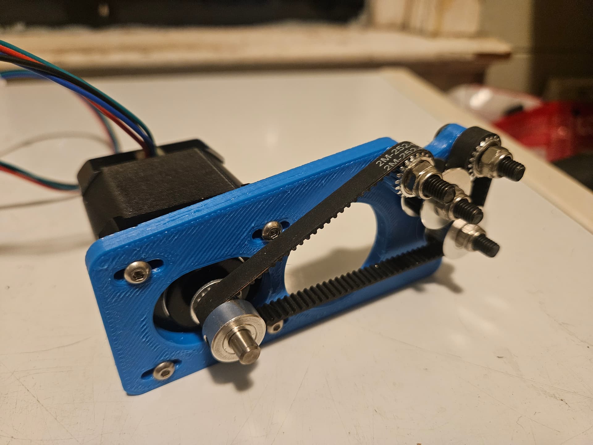
Based around a 252mm GT2 belt loop, features a 16T motor drive gear and 20T pulleys. The guides were removed from 2 toothed gears to allow the belt to stand proud of the gear and be the interface between the drive and the work.
The motor mount allows for 7.5mm of adjustment for tension.
This should give me a surface speed close to the target of 100 microsteps/mm, but it will be off by the difference between the tooth circle size of a 20T pulley and the size at the back of the belt, but this is a pretty small ratio. The math based on the theory gives me 96.46 steps/mm. I can probably just leave it at 100 if I switch out the rotational axis for X or Y and it’ll be close enough, but it’s easy enough to correct for.
So I pulled the Duet and put my Jackpot on this. The motors are set up as XYY. I did have motion, but have not used it a while, and now I need to laser some stuff…
X moves OK, Y2 moves OK. Y1 doesn’t move, but does lock.
At present, I have not had enough correct movement to actually try the laser, so not sure if it is set up correctly.
I wanted to do some.laser engraving for a gift. Can’t believe howong it has actually been since I’ve had this working.
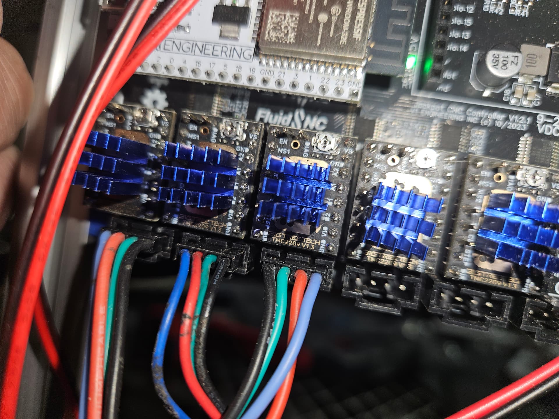
A pic of the motor wire connections. The paler blue are the wire extensions to X and Y2, the darker blue are straight to Y1 motor.
I also tried swapping the TMC2209 drivers with a different channel to see if it would help (it did not.) Edit: Wow, I managed to move those heat sinks around a bit swapping them…
Okay, so it is probably reasonable to assume that when you change something, and the machine stops working to blame what you changed. Maybe even moreso if you aren’t super confident in what you changed. I’m not super confident with FluidNC, so…
Nope.
I swapped the Y motors to eliminate mechanicalnissues and the problem stayed eith the Ymin motor. Oh? Start troubleshooting the wiring, the motor… that’s the only motor that does not have a wiring extension…
Hey what’s that? The belt isn’t tight around the motor pulley. It’s just close enough that when I try to pult pull the axis it locks, but if the motor spins… nothing. No power.
So apparently, when I swapped the board, I must have pulled the Y1 belt in the extrusion and loosened it. A quick adjustment, and voila!
Side note though, because I’d swapped the motors, homing failed, and I broke the lever arm on the Y2 stop switch. quick to fiz, but annoying.
Apparently I have the laser configured correctly, and I was able to do.a quick engrave… then I want back to LightBurn and swr the max power to 255 from it’s old setup of 1000… fortunately no damage done from 98% power instead of 25%…