Now that I’ve built my fifth table, I get to square the damn thing. I finally got tired of manually jogging the machine around, taking (and re-taking) measurements, and then trying to calculate offsets.
So, I (with some robot help) built a tool to:
generate gcode that drives around in a rectangle and pops down to pierce the table
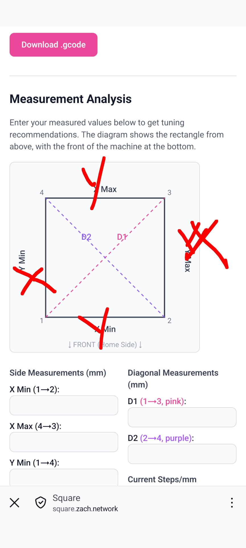
accept your measurements, let you know if you have broken the laws of physics, and suggest tuning.
I haven’t tested this yet (but will have by the end of the week). Feel free to poke around at it and let me know if you see something off. Thanks!
No, you don’t. If you know the length of two sides of a triangle, you can use the Pythagorean Theorem to calculate what the length of the third side would need to be to form a right triangle. So, in this example, measure the X and Y dimensions, do the calculation, measure the corresponding diagonal and if that measurement matches your calculation, you’re square, and if the diagonal measurement is shorter than the calculation, your angle is less than 90°, longer and it’s more than 90°
But that does not tell you that the other side (Y-belt) is square (at both ends). You can have a right angle triangle on one side of the table while simultaneously having a y-axis belt on the other side of the table that is not moving that side of the X-axis gantry the same distance (as the other side).
That is, you can’t tell if a rectangle is a rectangle by only checking one corner for squareness.
Personally, have been “hill climbing”… Use drywall T to make square enough for machine to move, then, calibrate Y steps/mm to account for Y belt pitch variance, then, chase sub 1mm accuracy using trig. Using a calc-guide like this for final step would helpful and neat.
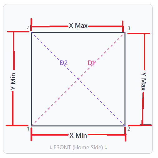
Personally would expect corners to be labeled for orientation, e.g. Xmin,Ymin, the numbers 1..4 are useful if guide is instructing to move corners to correct Squaring.
Sides are what Users measure, e.g. Front, Back, Left, Right. That seems more human friendly than asking to measure edge distance between numbered vertexes.
Consider input fields labeled with Side name. Users are just measuring distance along a side or diagonal.
Some people may use different orientations and labels for their machines, that’s fine, and it’s also fine for them to figure out the mapping for their setup that strayed from yellow brick road.
This ONLY works if one of the angles of the triangle is exactly 90 degrees.
The whole point of squaring is to correct for angles that are not 90 degrees.
Diagonal measurements (both diagonals) are the easiest way to confirm if all 4 angles are 90 degrees. The only other accurate way to verify a right angle that I am aware of is to use a very large contractors square on each corner.
TLDR - Measuring both diagonals is the best way to ensure that your build is square.
You missed my point. You can use the Pythagorean theorem to determine if one of the angles is actually 90°. You measure the two shorter sides, apply the Pythagorean theorem to those measurements and then measure the longest side, if the number from your calculation matches the actual length of the longest side, then you know that the angle opposite the longest side is exactly 90°. But if the measured length is more than the calculated value, then the angle is more than 90° and visa versa.
And, equal diagonals do NOT guarantee squareness. To ensure squareness, you must also make sure that opposite sides are equal length.
But you are only confusing the discussion. The point is to make sure that all 4 corners are square, right?
Introducing instructions to make sure that only 1 corner is square is incomplete.
There is a reason that almost everyone uses the diagonals to ensure squareness.
2 measurements. Adjust.
2 measurements. Adjust.
Which diagonal is longer tells you how to adjust.
Your method is
3 measurements, and doing some geometry calculations. Adjust.
3 measurements, and doing some geometry calculations. Adjust.
Assuming that you trust that you have equal travel on the Ys, as you noted, otherwise you also need to re-measure those both times too.
I’m not saying it’s not possible to use math in this way, I’m just not sure why you would ever want to do it over measuring the diagonals. It’s quick, easy, and reliable.
The only time I would use another method is if my tape measure wasn’t long enough to reach corner to corner.
It’s not incomplete, IF, you first make sure that opposite sides are equal length. Equal length opposite sides means you have a parallelogram and since opposite angles on any parallelogram are equal, if any one of the angles of a parallelogram is 90° then all of the angles are 90°.
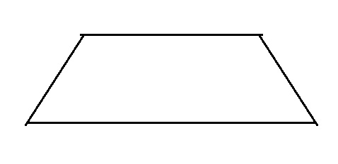
Measuring only two things is insufficient, you also need to make sure that opposite sides are equal length. This is an extreme example to make a point but, the diagonals in this figure are equal and clearly it’s not square.
Well, I suppose if your YMin and YMax motors are travelling different distances from a Y move command, your argument might make sense, but squaring would be the least of your problems.
The gantry will never change length during a move. Unless your Y belts have significantly different tensions, or unless you are skipping steps under an unloaded move, the Y distances won’t be different either.
The vast majority of squaring issues are when the 4 points create a parallelogram (opposite sides are equal and parallel). The likelihood of creating an isosceles trapezoid (opposite sides equal, only 2 sides parallel) is extremely unlikely, unless your machine has some serious issues.
Yes, it is a good idea to measure the distances from XMin YMin to XMin YMax and compare them against the XMax YMin to XMax YMax distance (and against the expected movement), but the likelihood is that 99.9% of the users won’t see a difference (or maybe a couple of mm at most), while a fairly significant number will find differences when measuring the diagonals.
You certainly are free to measure your build however you wish, I just don’t think that encouraging new builders to diverge from the YBR and follow you into the weeds is a great idea (IMO).
If your machine is misconfigured/misbuilt to be trapezoidal, that is uncorrectable with pull-offs alone. Pull-offs don’t shorten any side, and a trapezoid’s angles can’t change without side length changing (keeping the parallel sides parallel.)
This machine is a parallelogram in the ideal non-corrected case, but belt tension and build errors can lead to sides being different lengths. Since the X gantry won’t change size (…hopefully?) this means there’s no physical possibility of perfect squareness.
I actually worked through a lot of the process of squaring in another thread here — I am pretty confident in these concepts (though need to double check the implementation of the math.)
I’m not sure how to interpret your comments: if the tool isn’t useful for you, I don’t mind! I would sort of prefer if the discussion here was a little more focused on the tool and any issues using it, if you want to discuss squaring in the abstract maybe a different thread will do?
You guys are making it more difficult than it should be. Just built it carefully and you have a pull off difference of maybe 0.2 to 0.5mm, if any at all. I’ve never had to adjust anything.
Stop chasing 0s. It’s not going to matter too much even if it’s a bit off.