Thanks for making this.
If it had a ‘fire laser’ option in lieu of plunging a tapered bit that would be cool. ![]()
Thanks for making this.
If it had a ‘fire laser’ option in lieu of plunging a tapered bit that would be cool. ![]()
Laser assist would be neat. Am using my RDZ engraver bit, has 1/4" shank and some springy Z give, which helps if Z pull-offs at Xmin and Xmax are not fully calibrated yet.
TBH, I used the “Certified good enough ™” approach for a long time, and it works okay…. as long as you don’t try and cut a 2 meters long board that just needs to be square ![]() (eg: arcade cabinet, doors, …)
(eg: arcade cabinet, doors, …)
So… depending on the type of project you’re making, “chasing zeroes” might be more or less necessary
Also, calibrating the machine for squareness once in its lifetime won’t hurt anyways ![]()
I also had “creep” in the Y belts with the LR3, where the belt would slowly slip in the supports, slightly alterting the setup… so I guess checking once a year or before a big project is also good practice
How would you go about cutting pieces like this most easily?
I admire your build carefulness. My pull-off always needs adjustment after a new table and I still struggle with square-enough-for-cabinets!
Not exactly, if you move y axis 800mm and x axis 600mm, the diagonal should be 1000mm, this is known as the 3-4-5 rule in the construction world, 8ft-6ft-10ft. If something is off you move the y side to adjust.
Of course, you square your machine after verification of your belt tension, to avoid one side moving more than the other.
Sorry cant explain more. But there us a lot of videos about this (also, you can thake this with any measurements units. )
This can not happen with a LR.
Most of my builds come out really close definitely under 2mm diff on the diagonal test. Then I dial it in to under what I can measure.
After that though, it does not move. If you are not able to hold you square there is another issue with the endstops or screws moving.
I love the idea, this is handy. Easier than my instructions code for sure. I need to look at it more and see if it is suitable for a brand new CNC user.
I did not test it but how did you account for the offset from the end stops to the test point?
Yeah, they’re moving to a whole new table. ![]()
There’s no easy way out .. just careful measurement and adjustment
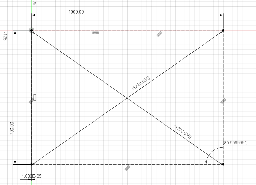
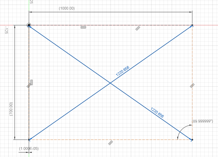
In my case, I have a similar “tool” in the form of a Fusion3650 design
I made a Fusion360 sketch with a rectangle roughly the size of my table
I have a laser attached to my toolhead so I used it, but you could use a pen
Measured the diagonals between marks
Went back to F360, switched the side Y side dimension to “driven” and the diagonals to “driving”
Put the measured diagonals in F360
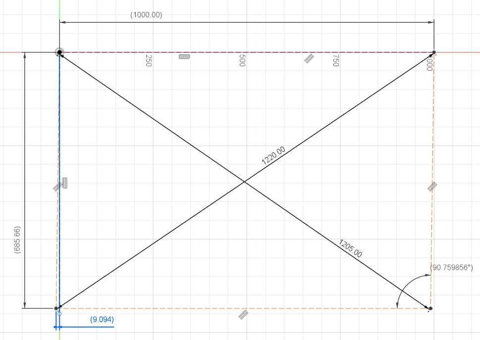
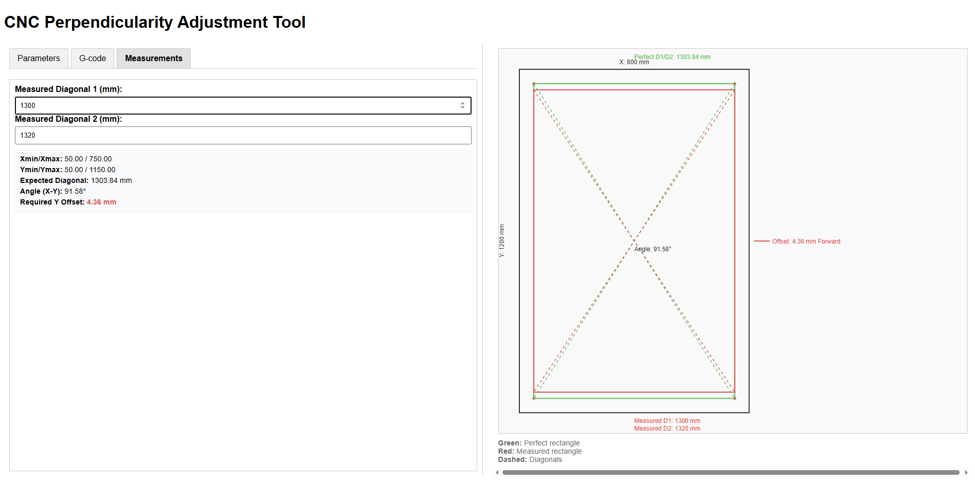
See the Y offset and adjust (capture is just a pretty extreme example for vizualisation…)
Rinse and repeat
Design attached below…
LR3 squaring.zip (109.5 KB)
Just to be clear, having something similar in a web interface is just great and maybe a lot simpler ![]()
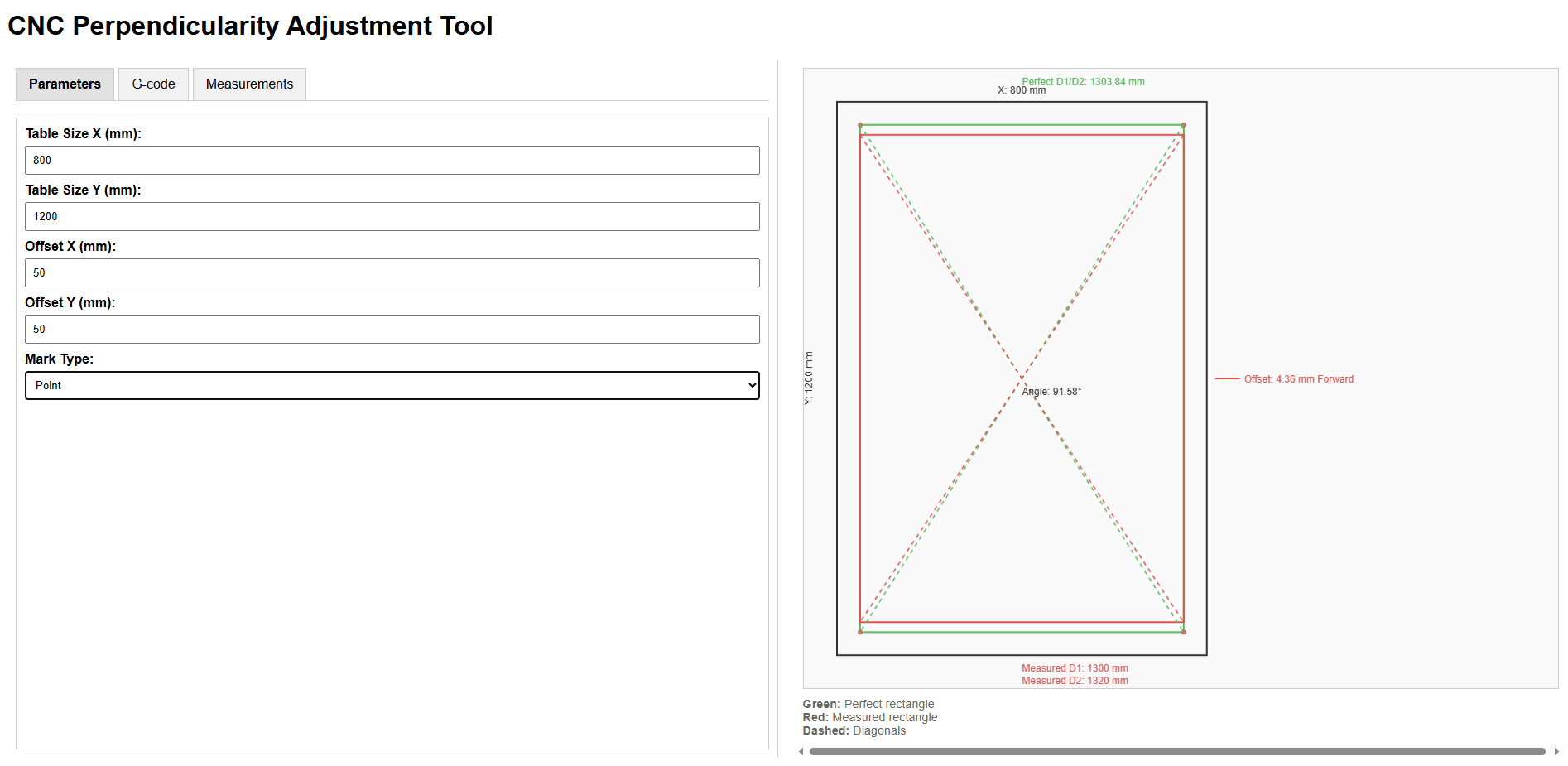
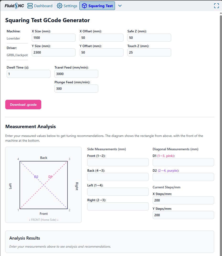
I tried the one linked above really quick and I find it a bit confusing:
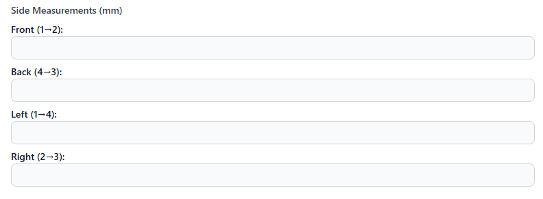
There’s no need to measure actual X vs expected X or actual Y / expected Y on this machine, it’s a bit redundant
This whole block could go away, or may be optional/hidden
If anything, make a second tool (although this test should be conducted first) to measure actual movement vs expected
Clear vizualisation of expected diagonal dimensions vs actual and their effect on squareness is critical for comprehension, maybe adapt the graph to reflect those, and display expected values next to the actual measurement input
See my diagram above…
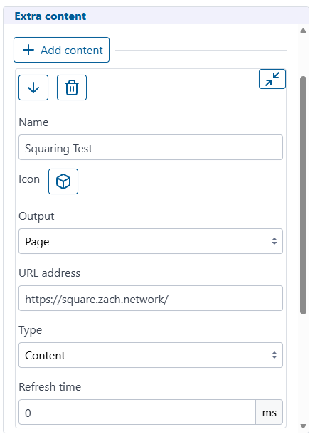
I’d love to have this as a FluidNC plugin too, this would be the easiest for new users…
If interesting in making it a real FluidNC extension, I can help if needed.
I think I modified my FluidNC to get around CORS, but this works for me. Also, only works if FluidNC running in STA mode.
Didn’t tag you explicitely but yeah, It was definitely a call for help ![]()
Can an extension read/write the machine config? That could make this all pretty automatic. If there’s documentation on writing one, I can take a crack at converting it.
This is not true. Adjusting the pulloffs precisely (and tuning steps/mm or tension) requires you to know how much you actually moved, not just how much you tried to move.
Yes. Same as you would do to update it via the terminal:
$/axes/y/motor0/pulloff_mm=123.456
$/axes/y/motor1/pulloff_mm=123.456
Here is some limited documentation I have that also points at the official.
ESP3D-WEBUI-Mods/Docs/Development.md at main · jeyeager65/ESP3D-WEBUI-Mods
And these are my extensions. The HoldMonitor is a really basic example and Joyjog at least reads values.
ESP3D-WEBUI-Mods/Extensions at main · jeyeager65/ESP3D-WEBUI-Mods
LowRider Endstop Adjustment v1.zip (40.0 KB)
I did this fusion project up some time ago to calculate endstop offsets.
The sketch lines on the sides represent the belts, and use the Belt_Width parameter. I didn’t parameterize the sketch all that much though, because the rest of the parameters just assume that you commanded a square, and got a parallelogram with equal length sides. (This may not be exactly true, but is probably close enough.)
In the sketch, you enter the 2 diagonal measurements, and the calculated offset is on the lower right.
Edit: LOL, I knew that I’d put a topic out there… Square your Lowrider by adjusting endstops
This has been discussed for the past 20 messages
If your machine doesn’t move thé right distance, or both Y side do not travel the same distance, you have another problem, and squaring is not your concern at this moment
Hence the recommandation : for clarity, this block should go away and be in another tool (verifying steps), or be hidden/optional
Not trying to say it’s “useless” , it’s just another concern, and as a user, I find it more confusing than useful the way it’s implemented right now
Eg: in a “quick setup wizard” program/fluidnc extension, I’d probably have these steps, in order:
That hasn’t been my experience, doesn’t help that my setup is mobile and seasonally relocated. Belts potentially stretch, parts crack, creep, move, etc…
Personally appreciate the idea of an intuitive clear guided setup wizard, and also, be useful for occasional sanity check 'n tune-up wizard before cutting/carving a project where you have some required precision/accuracy.
Neat to see such a setup/tune-up wizard appear in FluidNC.
Greatly appreciate this topic’s discussion and outcome. Very few of my projects actually need the ~0.1% precision I see folks often strive for when calibrating (1mm over 1000m span). Cheers!
I am confused. I am trying to do the steps 1 and 2 together. To do 1, at least, you do have to measure the sides. Is my mistake calling the tool ‘square’ even though it’s also helping with the first calibration step?
Yeah: I’ve moved my machine a lot, rebuilt it several times – I have had meaningful accuracy improvements by tuning the machine following this process.