I’ve been trying to cut cabinets. With some parts laid on top of each other, I realized they were slightly out of square, and all the same amount/same direction. I could tell this because they all have a ‘correct’ orientation where they line up.
This points to the machine being out of square. I drove it to all four corners (by homing, then entering manual instructions: G0 X0, G0 X1200, G0 Y2400, G0 X0.
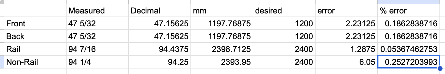
So one side is moving 3/16", or just over 4.75mm, over 2400mm. But honestly, none of the dimensions really make sense. I’m telling the machine to drive 1200 / 2400mm, but each distance seems off by a different % error.
I repeated the measurements 3x with the same results each time, so whatever is happening seems to be a problem with accuracy, not precision. I also don’t think that the diagonals mathematically work with the edges I’ve measured, so maybe my measurements are off?
Here’s what I’ve checked:
Grub screws - all tight, one on the flat.
Belt lengths - Y belts are the same length
Belt tensions - Y belts are folded with the same overlap, so no difference in the number of teeth from one belt to the other
Pulleys are different sizes - measured with calipers, all identical 9.53mm outer diameter.
At this point I’m at a loss for what could be causing this. Is it possible my belts are at different pitches? They all came in one kit, so that doesn’t seem likely. I can’t remember if I cut up one continuous length or had multiple pieces, but I think it was one continuous length.
Your first two measurements for what is normally X have identical errors, and we now know that not all GT2 belt is perfectly spaced at 2mm/tooth. The variability tooth-to-tooth seems low, it is more that there is a consistent error. With this knowledge, we now recommend doing a steps/mm calibration to address the variability in the belt.
Your last two measurements are way, way out- so this is something else at play.
My first question about those is: how repeatable are they? If you run them back and forth between their extent of travel, what measurements do you get? A sample size of at least 5 or 10 would be helpful to assesss this.
Your hand sketch shows an equilateral parallelogram, but is this born out with actual measurements? (E.g. at one extent of travel are the +/- Y tangential to the X, or are they truly as your figure shows? That would be very unusual indeed)
I took these across three repeats. Each measurement was within 1/32” or 0.79mm.
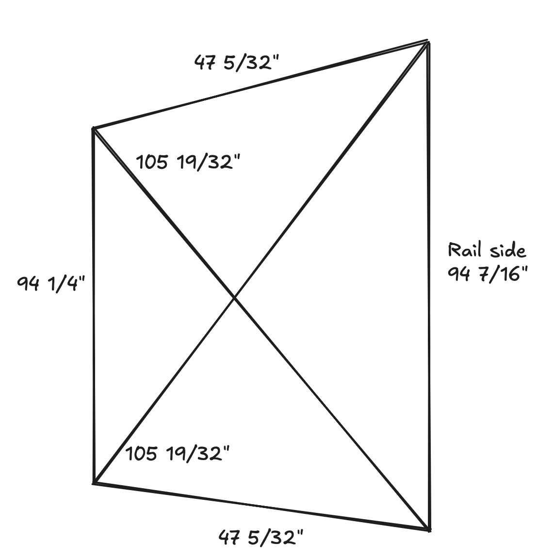
It’s a trapezoid. These are the four points I marked at each of the corners of my machine when driving around. It’s like the non-rail side Y stepper was running a bit short (or the rail side long.)
When your machine completes squaring, the Y endstop sides of +X / -X are not tangential to the Y rail?
The Y rail should be your frame of reference for all of this.
If the line formed by +X -X points is not tangential to the Y rail after you complete auto squaring the machine, you have to fix that first, then move on to the rest of the measurement.
I’m not sure what you mean by tangential, the only definition I know of that word is related to curves which there are none of. Do you have a picture that illustrates?
If you place a good square along the Y rail, you should find that all points of the X axis lie at a right angle to the Y rail as indicated by the square. That’s what the auto-squaring process at startup is supposed to do for the machine.
The math doesn’t add up in your drawing. Simple geometry dictates that the “X” section of the drawing (the two diagonal lines, not the X axis) cannot measure exactly the same if the opposing vertical lines and/or the opposing horizontal lines are measuring differently.
Are you sure that there wasn’t some measurement error (tape measure moved slightly, parallax, etc.) when measuring the diagonal lines as you squared the build?
I’m not sure this is true. An isoceles trapezoid has two equal-length diagonals. And since the LR4 X-axis can’t change (except due to measurement error, blocked movement, or skipping steps), this is a valid configuration.
Unless I’m misremembering my geometry? Very possible, it was a long time ago!
But the whole issue I’m trying to debug is why this is a trapezoid and not a parallelogram. The two Y-axis should be the same length, but they are repeatedly measuring differently on the board.
I agree that the math lines up with a trapezoid being able to have the same diagonals. The perplexing part is why a and b aren’t the same length. Are the belts from the same roll? If not, I’m questioning if they have the same number of teeth.
The belts came in the same kit, I think they were all in one long roll that I cut up (but I cannot remember definitively.)
I currently have the machine taken apart a bit (to check the pulleys for size differences) and measured the belts as having the same number of teeth by lying them on top of one another. One belt has 1/2 a tooth less than the other, but it’s in the folded-over portion in the stub. And I checked that the folded over portions have the same number of teeth overlapping!
I’ve ordered a new, metal, flat ruler to eliminate stretch and other measurement inaccuracies as a potential cause of this. I’ll reassemble the machine tonight and take pictures of all my belt locks to share with the class.
The other weird thing is that, geometrically, my diagonals are almost 4mm too long for the trapezoid I’ve measured at the edges. This is one datapoint towards a measuring error…
Yes, you are correct. I was assuming that at least on of the angles was 90 degrees. If all of the angles are not 90, then a trapezoidal would give the results seen. I withdraw my earlier comment.
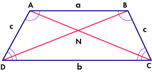
In this diagram, let’s say that a & b are lines that are in the direction of the Y axis, and that c & c are lines that are in the direction of the X .
In that case, because the gantry angle in relation to the Y rail should never change, angles C and D should always be complementary (should add up to 180 degrees). Similarly, angles A & B should also always be complementary. That is not the case in an isosceles trapezoid, where angles A & D are complementary, and angles B & C are complementary.
You mention that the LR4 gantry is a fixed length, but the gantry angle with respect to (wrt) the Y rail is also fixed, as long as the Y motors are moving the same distance. If they are NOT moving the same distance, then that might explain things, BUT they would need to be moving at the exact difference needed to make angles C & D to be equal (and non-perpendicular), and to make angles A & B equal (and non-perpendicular). This seems strange. Loose grub screws perhaps?
The car that runs along the rail can twist off the rail slightly. This angle doesn’t have to be 90’, they don’t have to be complementary (indeed, if they always were, we wouldn’t need to do any squaring in the first place.)
I think that is what’s happening. Or at least that’s what my current measurements indicate. This thread is all about trying to figure out why!
I’ve already had that problem before, and fixed it. I even double checked it before making the post:
If they were PERPENDICULAR, then squaring wouldn’t be necessary. But unless the Y motors aren’t moving in sync, then they should be always be complementary, regardless of perpendicular. If they are complementary but not perpendicular, then the diagonal measurements would be different, which is why we use that method to achieve square (perpendicular)
It feels like we are talking past each other a little bit. Thank you for being patient with me!
It seems like you are describing a parallelogram, which I agree is the expected shape for the four squaring marks/points in a working machine. I understand how to use pull-off adjustments to correct a parallelogram into a rectangle shape.
The problem I am trying to solve here is that my measurements indicate the motors are not driving the same distance. This results in a trapezoidal set of squaring marks. I am trying to figure out:
(1) are my measurements correct - will be double checking again this evening
(2) what could be causing this - consulting the forum, as I am really at a loss.
Not sure we’ve ventured into the motor side. The easy thing to check would be to swap the Y stepper plugs into the Jackpot to see if it follows the driver or not. Swapping the steppers themselves would be more difficult but would provide more data. I’m not sure we’ve ruled out wiring either. I don’t know if it makes sense to check these things or not given the behavior observed.
Also, curious if you measure it for half the Y distance. Is the error cut in half or does it stay the same? I’m not entirely sure what that tells us. If it’s cut in half, then things like belts having different spacing would make sense. If it stays the same, maybe that’s some kind of flex or binding.
This is an interesting problem and you seem to be careful with the measurements. 0.185in/94in is 0.2%
These are what go into the distance on each Y motor:
Software.
ESP32 goio output. Each step is a transition from 0-5V or back. We have had issues with EMI making these signals miss or get extra steps. But not with the jackpot and not for years.
TMC Driver.
Wiring. Intermittent wiring issues are a huge pain. But they are usually less accurate and less precise.
Stepper motors have an exact number of magnets to give them 200 whole steps per rotation. They couldn’t be off by 0.2%. They have a whole number of magnets and can’t have 200.4 steps.
Motor shaft to Pulley interface. You checked the grub screws.
Pulley diameter doesn’t matter. I wouldn’t trust a measurement of diameter to 0.2% precision anyway. But the thing that matters is number of teeth. You can’t have fractional teeth. So this isn’t it.
Belts.
Belt mounts
I would be surprised if the software or the TMC was the issue. Jason’s idea would eliminate them.
Belts are the obvious suspect here. Just as you pointed out above.
Some people have used steel core belts. The steel breaks and then the rubber stretches. Since you bought the belts from Ryan, that is not the case.
The fiberglass belts will stretch a small amount with different tension. They should be pretty resistant to stretch. But not perfect.