Space mouse v2 DIY

I’m also thinking about the possibility of gluing the globes on. Obviously that makes it harder to repurpose the joysticks, and would make repair/replacement harder.

I’m also pondering the orientation of how the globes are printed as pertains to the layer line adhesion weakness of printing, i.e. about the possibility of instead of them being a “one piece” print, being rather two halves, printed with greater strength where [possibly?] needed in the slender part, due to different orientation, and then glued together to make a stronger part. But having not put one together yet, that may a case of a solution looking for a problem that does not exist.

Hey, I went looking for the firmware file you offered, but Printables is now saying “404 not found.”

Did you take it down?

Just seen it’s been removed… :confused:

They are glued on mine, simply because drilling a 3mm hole through the joystick’s stem would destroy it completely

:open_mouth: any idea why?

I went ahead and drilled mine, but glue seems like a decent option.

could you share it here?

Here’s the “v3” file @Fabien had shared, before it was taken down from Printables. I’m glad I had already saved a copy of it.

improved-software-tt-spacemouse-v2-other_files.zip (210.2 KB)

1 Like

OK… well, I built mine, and it seems all good except I cannot get the 3Dconnexion software to recognize the new device.

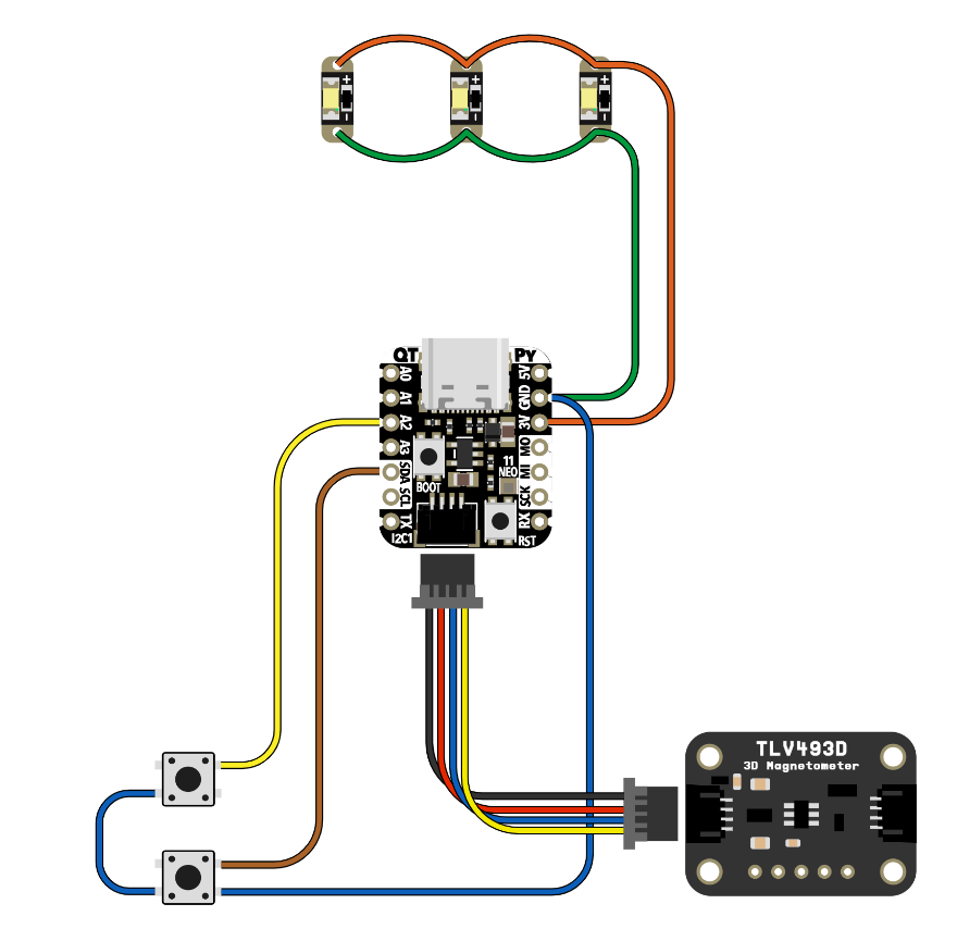
All my soldering seems good, and all my wiring seems good. All debug modes show it working fine in the Arduino IDE. I renamed the device to “Spacemouse” in the boards.txt, and edited the vid= value and pid= value as shown.

The device seems to be perceived by my MacOS as simply being a mouse. I can move the mouse cursor on my MacBook Pro screen… up, down, left, right, etc.

Pushing down on the stem, or pulling up on it, gets “transform” type values as expected in the debug modes.

At this point a most important step, getting it recognized by the 3Dconnexion software, is holding me up.

Some other tips for MacOS users:

The instruction in the video for Windows users … to copy an “AVR” folder into the sketch folder, and then go into it, and replace the contents of “boards.txt” is not the same on a Mac.

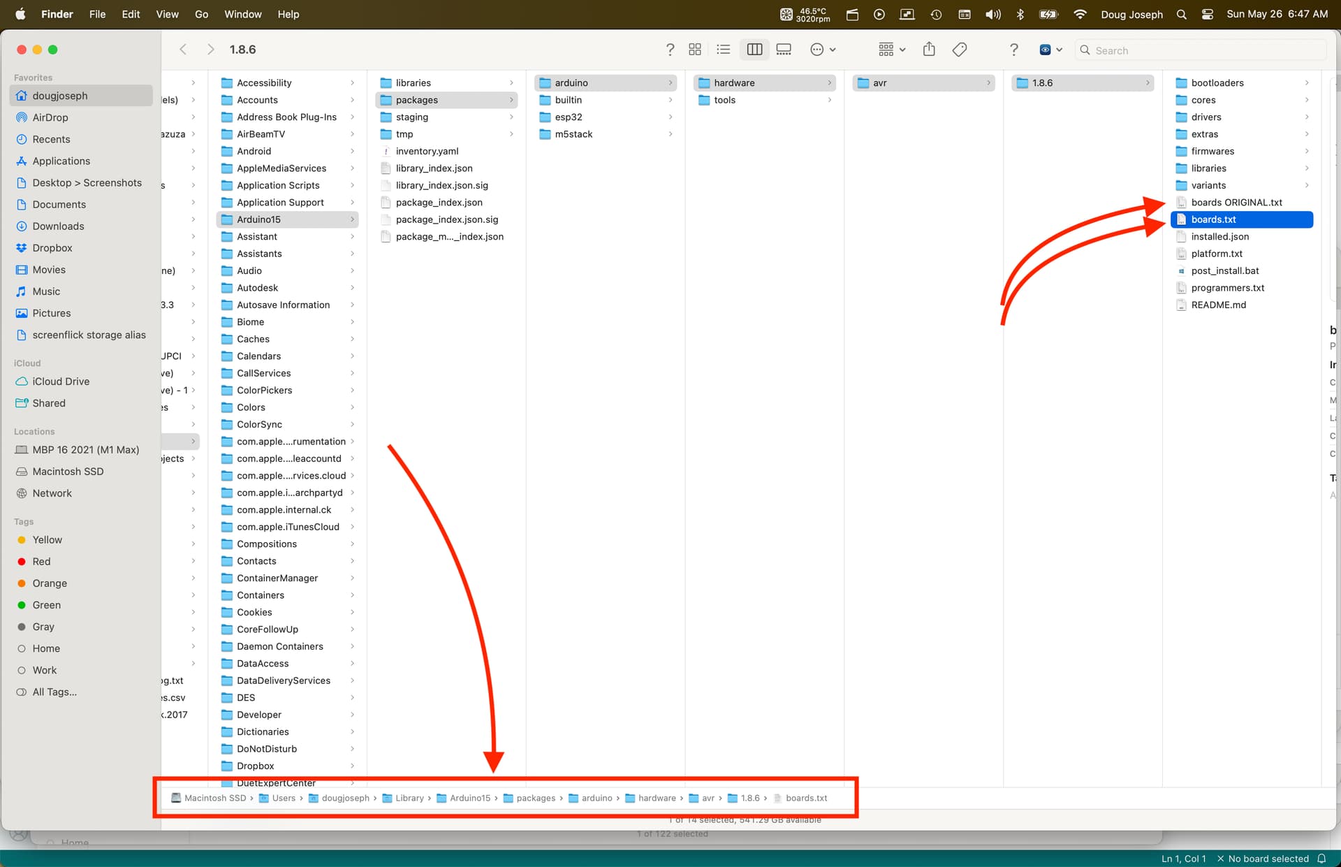
For boards.txt — on MacOS — how to edit Boards.txt was explained here (note the parts bolded by me): 'boards.txt' equivalent on mac? - #6 by bigrobintx - IDE 1.x - Arduino Forum

“resurrecting an ancient post, this is all i could find, and I have a bit different case. I’m using Sandeep Mistry’s Arduino Core for the Nordic nRF52xxx boards and as it is a downloaded package through the boards manager, and it uses a different processor core, compiler, and debugger (fun times!) there’s a bit more. After some digging I found the packages folder in the Library folder (open finder, click go, hold down option key and Library appears…) then in the Arduino15 folder you’ll see packages and staging… staging is like the downloads from libraries and board managers, tools, etc, packages is the live stuff… dig through there and in my case I found the boards.txt and variants folders as well as the json definitions of the package itself. Pretty slick. I’m using Kris Winer’s dev board and his board isn’t part of Sandeep’s package though I intend to submit it to him for inclusion. Hope this helps someone in the future.”

So, because I was editing the main boards.txt instead of a secondary one in a distinct sketch folder, instead replacing all the contents, I chose to merely add the new board details to the file, formatted like the others. This means that in the Arduino IDE app, I got a board choice of “Spacemouse” in my regular list of boards, not in a distinctly “in my sketch” location.

Here are some screenshots and my modified “boards.txt” in case it helps any other MacOS users attempting this build. In fact I’m including both the original boards.txt and the modified one. Their file names tell them apart. Use actual final filename of boards.txt.

Boards.txt, both Original and Modified versions.zip:
Boards.txt, both Original and Modified versions.zip (12.2 KB)

Screen shot of editing the file in its normal location:

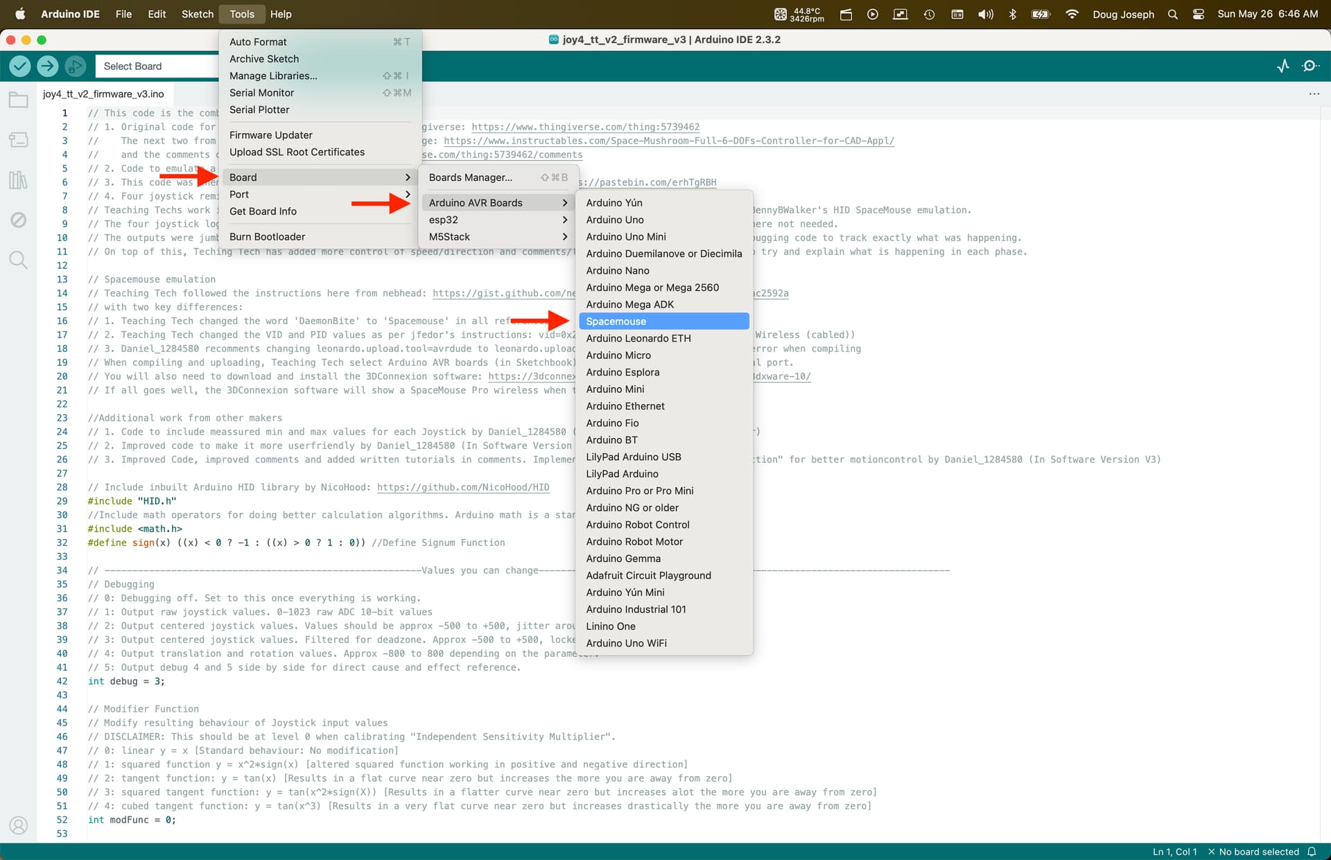
Screen shot of choosing the new “Spacemouse” board in Arduino IDE:

1 Like

Just a note on this firmware, at least for v3, I liked the way the teaching tech version worked. That is, push and pull the knob in the Z direction was for zoom. Translate forward and back would move up and down. This is swapped in this firmware version. There’s a variable to change it:

//Switch Zooming with Up/Down Movement
//DISCLAIMER: This will make your spacemouse work like in the original code from TeachingTech, but if you try the 3DConnexion tutorial in the Spacemouse Home Software you will notice it won't work.
bool switchYZ = true; //change to true for switching movement 

However, the code at the bottom to do this has the parameters wrong. I had to swap transZ and transY. This has the updated line.

if (switchYZ==true){
    //Original from TT, but 3DConnextion tutorial will not work:  
    send_command(rotX, rotZ, rotY, transX, transZ, transY);

Although, if the real one works the other way, I assume I’ll switch back.

1 Like

OK, so my ongoing saga continues regarding getting the device recognized by the 3DConnexion drivers.

I have Parallels Desktop software on my MacBook Pro, which has an M1 Max chip, and thus my Windows install is Windows 11 Arm64 edition.

When I install the 3DConnexion drivers on the Windows side — two things.

1. It recognized my device as being a Spacemouse Pro, exactly as intended! Hooray! :smiley:
2. The latest 3DConnexion drivers won’t install, because it polls the Windows 11 ARM64 edition and misreads the response, and thinks the Windows version is too old or something, so an older version of the driver has to be installed. Details here: Windows 11 ARM driver - 3Dconnexion Forum

Quote:

I am using for Space mouse drivers version 10.8.3 on Window11 pro ARM 22H2 virtualized via Parallels desktop on MacBook Pro M2max. It works fine.
However newer version 10.8.16 incorrectly identifies Windows version and does’t install.

Meanwhile, for whatever reason, the Mac version of the 3DConnexion drivers does not recognize the device.

Pics of my build! This is based on @Fabien’s thin profile remix, plus my flush mount remix of the lid. I did @Fabien’s idea of hot-gluing lead strips for ballast.

I have posted this make over on Printables, including some additional details.

5 Likes

Looks like all your neighbors need to get the tires balanced :joy:

6 Likes

I looked for affordable sources for lead to use as ballast, and I eventually landed on recycled tire weights being sold as scrap, typically on eBay. I got 11 pounds of scrap lead for less than $2 a pound. There may be a better, more affordable source than that, but it was not to be found when I looked. That was the best I could do.

Magnet version is coming along quite nicely…

I hope I won’t have too much trouble with the software…

5 Likes

Jinxed myself… -_-

So… I couldn’t find the exact same models as the BOM for RPI2040 and magnetometer
I thought “hey, this one should be close enough right?”

And now, here I am, looking at pinouts that just don’t match >_<
If anyone clever-er than me in this field can chime in and take a look, that would be greatly appreciated (I ordered the BOM specific hardware on ali via the slow boat in the meantime so…)

Here’s what the BOM calls for:

Of course, being an Adafruit “plug and play” type of kit/component, the wiring diagram is pretty much useless:

And here’s what I got:

The magnetometer calls for this wiring diagram, but I can’t figure out where those CLK/MOSI/… pins are on my rpi2040
image

Pinout of the RPI2040 board:

If we can figure out the pins, I’ll probably continue with those, otherwise I’ll just have to wait for the next delivery

4 Likes

I got it working, with the V3 software, thanks for (re)sharing! Now for some finetuning

1 Like

Can you link the source for the RP2040 pinout? AFAICT it’s identical to this pinout from waveshare… but it’s rather hard to read. Waveshare’s copy seems to duplicate a lot of labels; half of SPI is for SPI 0 and the other half SPI 1.

If identical, my guesses about SPI are numbered (poorly) in the pictures. SPI only defines a few signals, so I’m not sure what ‘INT’ and ‘NC’ are, but I’d assume ‘CS’ is chip select.

On the PR2040 pic, nothing links CS (labeled ‘A’), INT (‘B’), and NC (‘C’) to the ICM LPS and MMC pins. I’d probably link A, B, and C to one of the many CSn pins and see how it responds.

Magnetometer is labeled serially from 0 to 7:
magnetometer

RP2040 labeled all the copies based on Waveshare’s enhanced pixel count:

I hope that’s useful – I’d like to build a space mouse as well.

2 Likes

I will try this.
I think I’ll need t declare the matching pins in the arduino sketch too? that’s a lot of unknown variables to deal with :confused:


In the meantime; I’ve been thinking about another contraption for a spacemouse… I kinda like this idea…

I found this model of a XY Flexure plate…

What if we stick a joysick on this… ?

And add some slide potentiometers on the sides?
image

This would still lack the twist and up/down motion…
I think a custom flexure design could take care of the twist aspect though

The more I look at it, the more I see potential in those flexure designs for this kind of application…
eg. what about this one?

5 Likes

Looks exiting!

Might be worth nothing, but I’m having fun mocking some ideas… Printing a few prototypes to see if this would work…

Combining this “flexure” approach with a magnetometer could yield a great potential

3 Likes

I was thinking the magnet could be in the sides and in the bottom and the chip in the middle?