I recently got my first mpcnc up and running, but I’m having a few issues that need fixed before its ready and I simply cannot figure out my issues.
First, my build has a usable area of 19’‘x39’’, but when my code or when I manually try to move passes 200x200mm the unit seems to hit a false stop of sorts. I’m not sure if its the firmware or what but something is locking out the steppers.
Second, I am using fusion to create the parts and code, I’m well versed in 360 for printing but CAM is new to me. I created a 9x9 part with some simple hexagons to test with, processed everything following the youtube video apocalyptic squirrels posted. I then zeroed the tool at 0,0,0 and it jumps out about 10in on a diagonal to make the first cut. It was almost at the edge of my stock so I shut it down. From zero to the first cut on the model is about 6-7 in on a diagonal. Could this a steps per in/turn issue?
Lastly and least of concern, after zeroing the tool I have to raise the Z above the height of the stock otherwise it will drag the tool across the edge of the stock. Moving it manually has been a quick work around, but if I could find the setting that allows me to just zero and hit print I would be much happier.
As the title says, I have the skr pro board flashed by V1 using fusion 360 and the post processor linked on the site. I have the makita tool setup, but it holds a cheapo harbor freight trim router or a marker.
At a glance, those all look like they should be inside your stock, presuming the origin is at the bottom left. First two things is check is that the xy actually reset to 0,0 and that when you jog 20mm or 50mm or whatever, you actually GET that much movement.
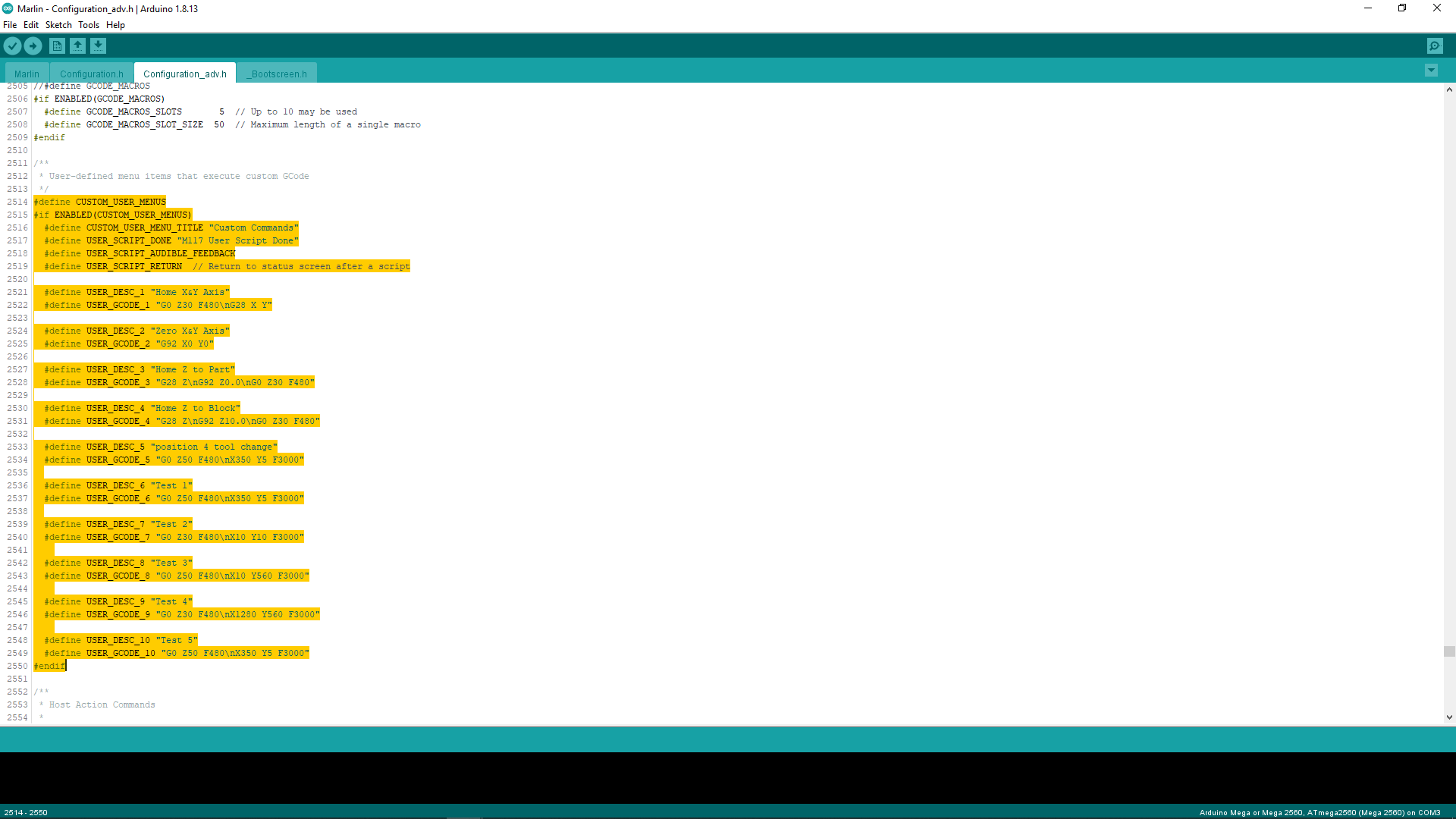
As for the z, you can add a menu command in marlin and reflash it to include a z zero macro of sorts. Or, if you’re running from a computer most interfaces have an option for this (I like cncjs, repetier host is also popular).
The false stop is probably the bed size in the firmware. I think you might have to reflash for marlin (but I honestly can’t remember for sure), grbl you can set from a console.
Upside, these are all common issues, and correcting them will be easy once we get to the bottom of the cause. There is so much knowledge here that you should have it sorted quickly.
Hi, hopefully this will help, first question is are you familiar with how to flash your firmware?
First, my build has a usable area of 19’‘x39’’, but when my code or when I manually try to move passes 200x200mm the unit seems to hit a false stop of sorts. I’m not sure if its the firmware or what but something is locking out the steppers.
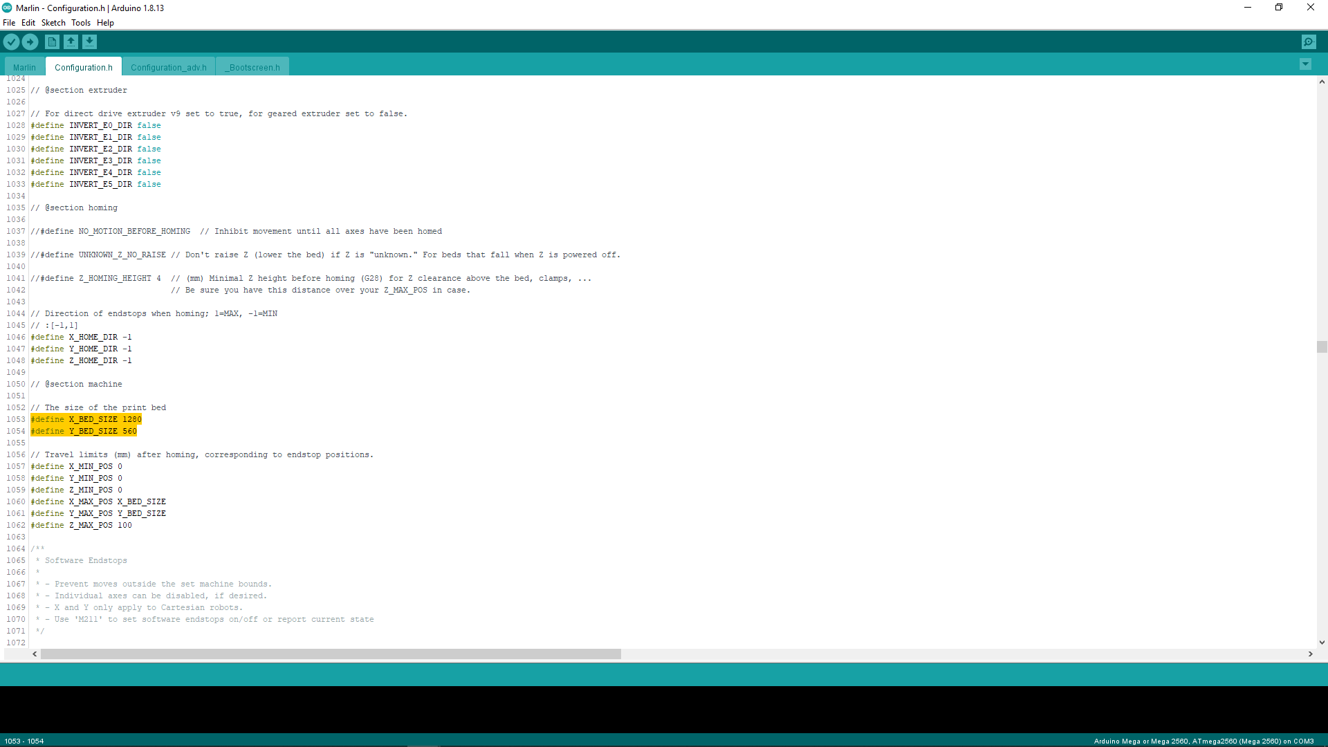
You will need to set YOUR bed size (physical cutting limits) within the firmware. (see picture)
2.Second, I am using fusion to create the parts and code, I’m well versed in 360 for printing but CAM is new to me. I created a 9x9 part with some simple hexagons to test with, processed everything following the youtube video apocalyptic squirrels posted. I then zeroed the tool at 0,0,0 and it jumps out about 10in on a diagonal to make the first cut. It was almost at the edge of my stock so I shut it down. From zero to the first cut on the model is about 6-7 in on a diagonal. Could this a steps per in/turn issue?
With Fusion you will need to set the stock origin in the CAM tool-path setup at the bottom of the stock and set zero stock to leave at the top if you want to cut right through a piece if you set it on the top it will cut in mid air. You need to set the Z zero on the MPCNC to just touch the top of your work-piece not the bed. the issue that it moves to the middle may not be an issue at all it could be that Fusion has simply optimized the tool-path. Best way to check it everything is likely going to do what you want it to is simulate it onscreen before you run it. Go to one of your setups, then one of your cutting operations, right click and press simulate you will see a play button at the bottom.
Are you using a Z probe or are you manually setting the height, reason for asking is that if you are using a probe it will be easy to to write a couple of scripts to cover what you need and put then into a custom command, like picture below.
You do not need to set your bed size. This is only used to judge how far the machine is willing to go before quitting when homing. Just make sure your machine is within 200mm of the home switches before you home (if you are even using endstops).
There is a soft stop feature that can limit the max distance when jogging, but it should be turned off. If it isn’t, then check to make sure you have the right firmware. Otherwise, maybe we have a bug in our config. But max soft stops should be turned off.
Thanks, I’ll look into modding and flashing the firmware.
I do set 0,0,0 on the bottom corner of the workpiece in the CAM setup, But I also set 0,0,0 on my cnc bed before I raise it and place the stock. so thats probably part of my issues, but i’m not cutting in mid air so that probably backs up the idea that my in/turn isn’t right.
I do simulate but i am only cutting pockets so the tool starts right over the first cut and progresses from there. I cant see how it moves from the origin.
Let me get through this work day and I will move 100mm and see how close it is to 4in. I really wish I had a metric tape laying around so I wouldnt have to convert between the two and cause more confusion.
What setting where controls how far the machine moves with each turn of the stepper?
I’ve got a few test pieces that have a flat side at 200 when it should have kept going. I have no idea what features you’re talking about but I can say 100% that something is locking out my steppers at 200 whether I’m using the code or moving with the screen.
I dont know what that means. I am running the machine off of an sd card not via my pc. Is there a way to run commands from the screen? or should I pull the header from the gcode I have and add that after start begin?
To get the data that Jeff is asking for, you will need to connect a computer to your control board and use some sort of g-code sender. Based on forum, the most common g-code sender for the MPCNC is Repetier-Host. Once setup and connected to your powered control board, you will use “Connect” in the top right corner, select the “Manual Control” tab. Type the M115 into the G-Code edit field and click Send. Copy the results at the bottom of the screen and post it here.
The reason i told him to set his bed size is that you can turn the soft endstops on and off within the screen menu under motion and that may well be the case, as he is only travelling 200mm in X/Y and the default clean firmware states that table size as 200 x 200mm it is likely that he is hitting those soft endstops. I fully understand that if the soft endstops are off you can push it beyond the 200mm default, but i don’t see why asking him to set his bed size in the firmware should be a wrong call, with the machine homed and the soft endstops on it will only stop the machine crashing and causing further issues. Confused?
I’m just guessing based on Jeff’s comments. Soft endstops should be off/disabled in the firmware managed by V1, so either Jeff has a bug in the firmware he manages, or Joseph has the wrong firmware installed, or some third choice. The data from a M115 g-code will tell which is true.
If Joseph want to try setting his table size to his actual table size, it cannot hurt, may fix/hide the problem, and is a good idea if he is using dual endstops. Note that I had a similar problem (coordinates were a bit different than he describes), but it was not soft endstop problem.
I don’t think anybody is saying it’s the wrong call. Just that it shouldn’t be the problem (of course it MAY be the problem, and I thought so too, way up above).
I think if you are on a gcode sender(as many of us are) sending the query is easy, fast, and efficient. That’s all. Flashing firmware is a bit more time consuming and challenging for some, so making sure it’s the problem first might save a lot of frustration, even if it involves getting ON a gcode sender.
It’s not a “right” vs. “wrong”. But many people are not compiling the firmware at all, and just use it as flashed. The firmware doesn’t include softstops by default and doesn’t care what the bed size is. If this is the only reason to compile the firmware, and you’re not comfortable with it, then that can add a big hurdle.
I compile my own firmware even if I don’t change anything. But I am not everybody.
Laid out a 20x20cm grid. 100 units x or y is about 152mm on the grid. So my steppers are moving too far.
Using the terminal. M115 then enter. The screen says send:m115
Touch anywhere to exit… nothing happens
Probably not what you were looking for