You are probably right, but I would really like to keep this plotter unconstrained on the wheel axis if possible since that was my initial intent. When installing the bearings in my latest wheels that have the 2 access slots from the bottom (22.3mm bearing holes), I noticed they were about the same fit as they were with the 22.4mm. Those holes might be hurting my precision. Making those a tighter fit will be the only other thing I can think of to change that might give more accuracy. I will see how the new wheel endplates work first. I found it interesting that my pen was only 3.5mm off at end of plot when running at 1800mm/min & 1000mm/min. The wheel spacer idea you told me about gave me enough accuracy to motivate me to continue working on this idea. I have the wheel stepper motors attached to 2 different drivers & guess they could get out of sync. The 2nd wheel stepper is attached to E0 driver. I had a thought about your rack & pinion track you used on another design. That track would lend itself nicely to be printing on one of those 3d printers that prints on a conveyor belt so there would be no joints. How did it work for you with the joints in that rack? Is there a way to print that track with joints that do not affect the smooth movement along that axis? I have also toyed with the idea bigger diameter wheels, maybe 100mm which I have seen in the other similar designs on openbuilds, but I would have to 3d print the TPU treads for those. I have not seen o-rings that big. Do you think bigger wheels would be any better?
First, I don’t think guides would be absolutely necessary if you’re not doing anything requiring any precision. Sand plotting, sketch drawings, etc should be fine “un-guided” I would think… although I would still want them to track as parallel as possible, to minimize the drift.
I have the motors on my tractors wired in series… ala MPCNC. I’ve never any sync or imbalance problems with them hooked up this way.
Not sure how you might use the rack and pinion idea (as “track” to guide/run on?) but the joints were not a problem at all. I have an Onshape rack design with ONE tooth… which you then “linear array” to the number of teeth you want/need. My printers can only handle a rack section a little over 8" long so that was the longest rack section I could do. On my R&P MPCNC I just staggered the joints on opposite sides and never noticed any issue at all when plotting rulers, crowns, laser engravings, etc.
I’m not sure the effect bigger diameter wheels would have. Playing with my machine as I have been, I have come to the conclusion that this is not the most stable of machines… when I gently wiggle the machine from the top of the Z-axis stage, the whole machine rocks, pretty much in any direction. Anywhere a “wheelbase” could be increased (tractors and linear stages) would help the cause… though it’s probably just fine “as is” if only light loads – pens/markers, needle cutters, lasers, etc. – are all it ever sees.
BTW you are welcome to any of my STL’s if you think they’d be of use to you. IIRC you once mentioned the extrusion “pass-thru” on the end-plates and the Z-axis linear stage… and I meant to offer them to you then but I forgot… 
– David
I ran 3 tests today with new endplates without any better accuracy so will reprint the wheels without recess holes & 22.3mm bearing size which fits very tight without the recess bearing eject holes. I ran initial test at 1800mm/min, then 3000mm/min & also 3600mm/min. Interestingly the 3600mm/min seemed just as accurate as the 1800mm/min. It won’t be until Monday or Tuesday before I can run a test with new wheels.
I got the new wheels installed. The carriage belt has a better tension on it than before. I ran it faster today at 4800mm/Min or 80mm/sec and was a hair more accurate at off only about 3mm at the end, but had some pen skips. Skips are probably mostly from the pen not lowered enough. I ran it again at 1800mm/Min and was about 2.5mm off at the end. I really need a better z-axis than the servo. I have a couple of nema17 pancakes now that I can try. I was also thinking today about using tank tread printed in TPU. That would give me more gripping surface. Will have to research some designs for ideas for this. Not sure that would give me anymore accuracy, but would look cool. Here is a video of it running at 4800mm/Min.
Instead of using tank treads, I had a thought this morning about 3d printing a TPU tire to wrap around both wheels. Not sure whether I can get it to print or not, but would give more surface area for traction if that is the problem with accuracy. A 3/4" thick rubber band on each side would probably be better & just wrap over the o-rings, but don’t have any of those. Looks like a #94 rubber band (3.5"x3/4") would be perfect, but not sure I want to buy a box of 140 from Amazon. Maybe I can find a smaller quantity from somewhere else. #84’s would be the 2nd rubber band choice at 3.5"x1/2". I can find them at a Staples store not too far from here for $2.73 for pack of 45. I might have to go by there. Here is kind of the idea I had for the TPU tire.
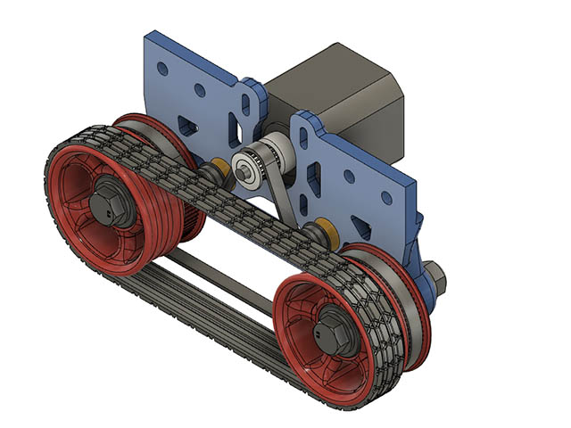
The rubber bands I have are just not going to work. One came off early in the plot & the other came off a few minutes later. I did find some 7"x1" rubber bands from Grainger for $6.55 for a pack of 5. Those should stay on a lot better, but not sure I want to spend anymore on rubber bands before trying the 3d printed TPU 2 wheel tire. It is a 2.5 hour print per tire at 30mm/sec & a few layers into to the print it is behaving nicely.
I added the same tread pattern as my original TPU single wheel tires. It will not be as grippy as the o-rings but with the more surface are touching the ground seems like it should be less slippage.
Not that I believe the rubber bands are going to be best for this application… did you “crown” the wheel where the band rides? If you’ve ever used a band-saw… the upper and lower wheels are “crowned” (rounded and high in the center) and the steel blade/band is easily adjusted to track properly on the wheels. That might help keep the rubber bands from coming off in future tests…
I was slipping the rubber bands over the center o-ring. I also tried taking the o-rings off & putting the rubber band directly on the wheel, but didn’t seem like it was going to work, so I didn’t fiddle with it much. Putting a few of them on there might work, but didn’t bother. I will try the TPU wheel before playing with the rubber bands again. They will not slip off as they are caught in the grooves. Hour into the print & still looking good.
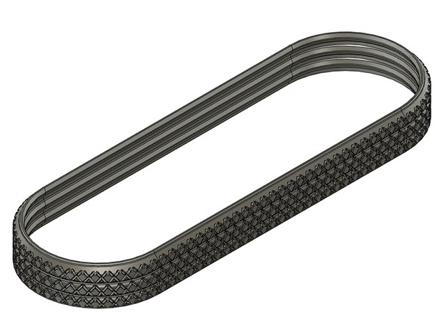
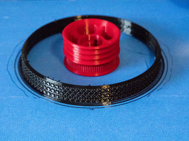
After fitting the 1st TPU 2 wheel tire on it seems a little loose and probably should be printed in circular pattern instead of the way I printed it since it has kind of 4 creases where it is tangent from the circle to the straight line. Should also be a little shorter perimeter since it stretches. That is probably why a tank track works better than this style because it is difficult to get it a tight fit. Perimeter going around both wheels of where the center of the O-rings are is 415.24mm which should give me a diameter of 132.175mm. Since I can stretch tight about a 16mm diameter around motor shaft that comes out to about 421mm perimeter, so I will shorten it the diameter of the tire to be 6mm (1/4") shorter perimeter. I will round down to 130mm diameter. On a positive note that is 6mm less length of tire to print. Still might not work, but worth taking the idea a little further. 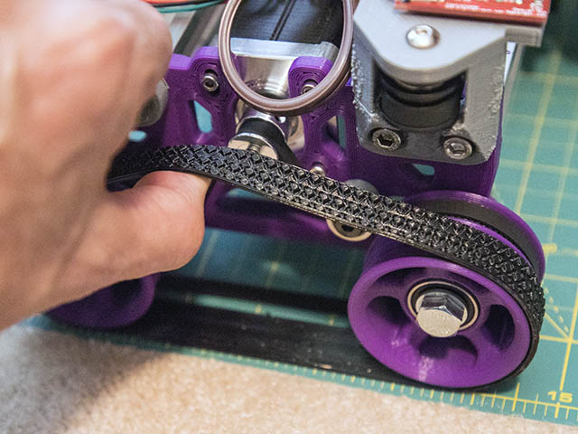
This looks like it stretches more than a 1/4", but that is what the perimeter measures. I might go 9mm instead of just 6mm.
I adjust my 3d printer some yesterday & it is happier printing TPU today. I still have about 3mm difference in height from gantry from one side to the other, but can’t find what is out of square. I did find one M3x30mm bed adjustment screw where the threads were stripped. Don’t think I have ever stripped threads on any of that stainless steel hardware. I managed to get the screw out without getting my dremel involved & is easier to level the bed now. Adding some glue stick to the bed was the final thing that helped getting the tire to print.
The tire print has an outer diameter of 132.3mm. I still have to cleanup the inside of the tire from the nozzle oozing. I wanted to fit in place before starting the 2nd tire print. Hopefully can test it tomorrow. Gripping wise, the o-rings still seem better on the cutting mat surface I am using to roll the printer on, so it may not be any better.
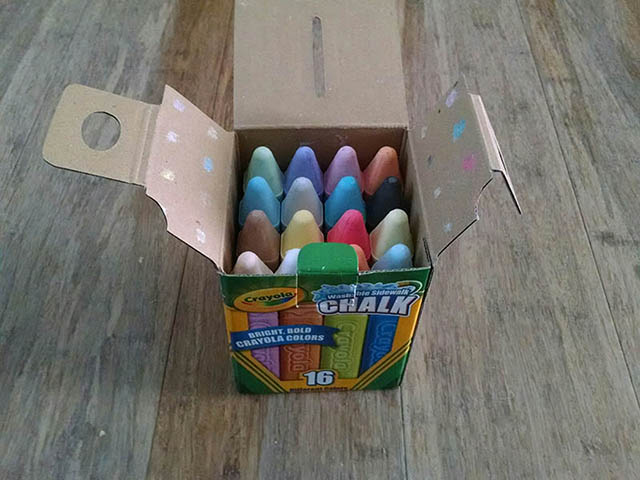
TPU tires did not work as well as o-rings on the cutting mat surface which I was expecting after feeling the grippiness of the 2. A more textured rolling surface would probably help or maybe the wide rubber bands, but that is all I am going to do with this until I get another inspiration. As the test goes, the wheels actually started going crooked after a while which that has not happened since adding the bearing spacers. I was also off 11-12mm at the end of plot. The TPU wheels would probably work pretty good on concrete or asphalt. Maybe I will try it outside sometime. I have an outlet near the driveway. Ooh, and I also have some chalk I bought from Dollartree.
Anyone have suggestions for a 14"x 6 foot or so long pattern to draw on Concrete? Looks like I will need a better grade of chalk before trying this. The Crayola chalk that dollartree sells breaks too easily.
This looks like the chalk I need. https://shop.crayola.com/toys-and-activities/sidewalk-chalk-12-count-5120120002.html Think there are a couple places locally that sell it in 16 & 24 color packs.
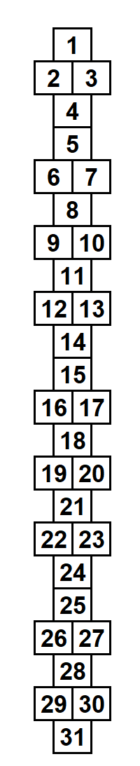

That looks like an extended game of hopscotch, good idea. https://en.wikipedia.org/wiki/Hopscotch
Probably be next week before I can get the chalk.
A maze might be kind of fun, but might be too long a print. http://www.mazegenerator.net/
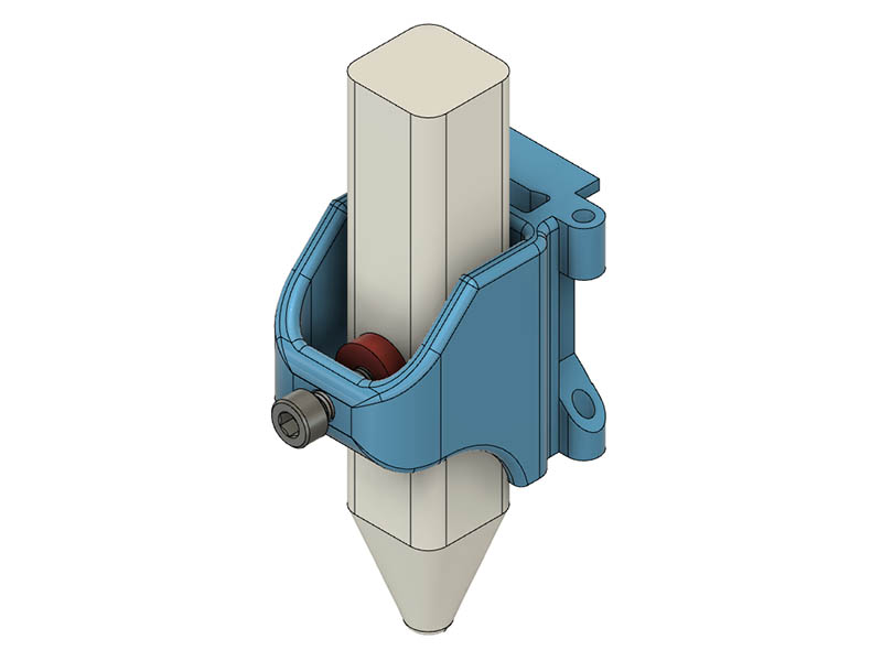
I got the chalk yesterday from Lowe’s & these sticks are 20.5mm width across them which is bigger than my current pen mount. I made a mount big enough for it & will print it today. I changed the tightening screw from M3 to M5 & added pressing washer at the end for more surface area grip.
I am slowly getting back to this build after getting all the parts I need for the portable Ryobi portable P/S. The DPS5005 part was the last item to arrive.
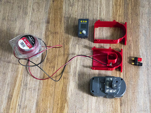
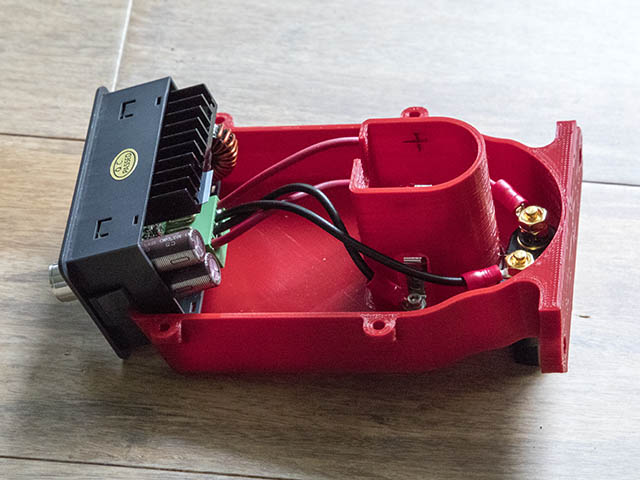
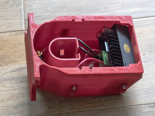
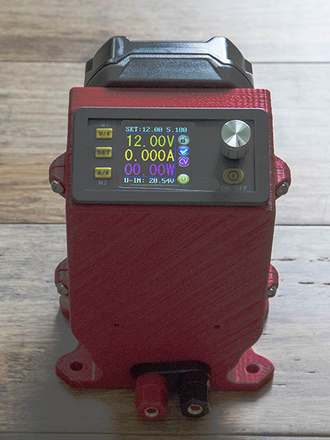
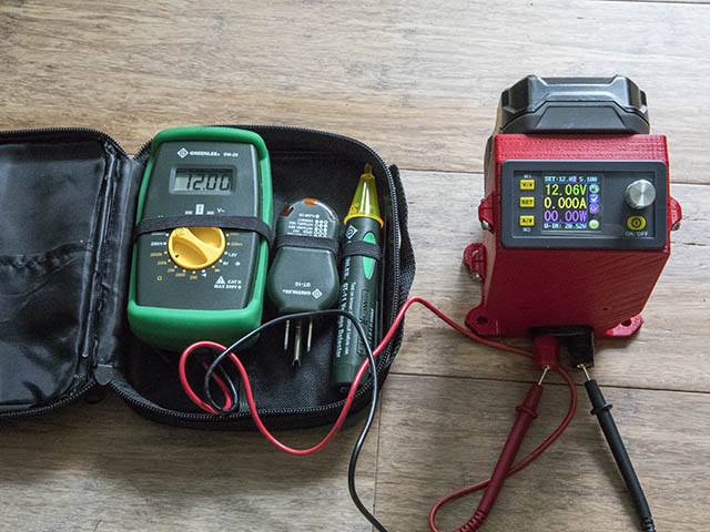
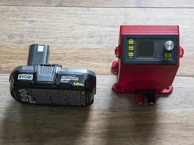
I put together all the parts today. I used https://www.instructables.com/id/Battery-Adjustable-Power-Supply-Ryobi-18V/ instructable for this. I redesigned his case to mount on the 2040 V-Slot & after spending over 5 minutes trying to get those battery clips in place & then drilling some access holes in the plastic to make it easier, I decided that was enough frustration & made it a 2 part design. Needless to say that made it a lot easier to hook up the wiring. I made the Battery wires about 3.5" long & the Outside post terminal wires about 4.5" & used M3x12mm screws to hold the 2 plastic parts together. The DPS5005 is not as tight a fit as I like, so I may redo one or both of those plastic parts. The On/Off switch on the DPS5005 does not turn the whole thing off, but seems to only turn off the output. I set the DPS5005 to 12.06v to get 12v on the terminals & probably will just set it to 12.1v or so. The original designer suggested using 18gauge wire, but I used 16gauge which is what I had. I only have 1.5ah ryobi batteries, but you can also get those batteries also in 2,3,4,5,6 & 9ah sizes.
Here are photos of the assembly.
Here is an interesting idea of making urethane wheels at home. Don’t think I will try it anytime soon, but others might want to consider this. Probably would have to modify his design some to work with this rolling plotter. Casting Skateboard Wheels With A 3D Printed Mold | Hackaday
He also has some other interesting projects on his website. Projects — Good Roads Collective
I have not done anything with this in a couple of years but got inspired to work on it again. I never carried thru with the Ferris wheel gear idea & want to pursue that a little deeper to see if it can work. I ran into one hurtle with fusion 360. They apparently no longer allow you to use addons with the personal version, which the herringbone gears I was creating used that addon. I decided to watch some tutorials on freeCAD & that almost does what I want.
The inside ring gear might be a little bit of a headache with freecad, so I am back to Openscad. I found another Openscad gear library that I missed before that was originally written in German. This guy wrote a front end for it to make it easier to understand, OpenSCAD Gear Library with Customizer by eleotlecram - Thingiverse . I decided to just pull out the routines that I needed from the original source, Getriebe Bibliothek für OpenSCAD / Gears Library for OpenSCAD by janssen86 - Thingiverse. I used google translate along the with English front end as a guide to translate the variables to something I could understand. It worked pretty well.
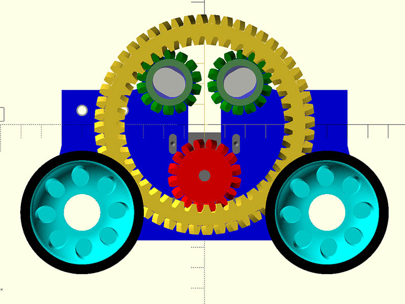
Here is where I am so far with the design. The big ring gear (yellow) has 52 outside teeth & 41 inside teeth. The motor drive gear (red) has 16 teeth & the idler gears (green) have 14 teeth and the wheels (cyan) have 25 teeth. I wanted to use 608-2RS in the idler gears, but there is not enough room unless I widen the wheel spacing by another 20mm (use 2080 between the main 2040s instead of 2060). That might still be a good idea. From my 1st test, the ring gear would probably be at least 12 teeth bigger. Not sure if the bigger gear would help or hinder the driving of the wheels. Anyone have thoughts on that? I will probably put a flange around the drive & idler gears to help keep the big wheel in line. I slotted the bearing holes in the blue plate for the idler bearings since they might need to adjust. Not sure how well that will work. Think I will need 16 extra bearings for the idlers which is the same quantity I have for the wheel bearings (2 in the plate & 2 in the wheels).
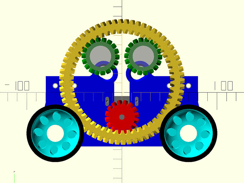
Here is 1st stab at wider wheelbase with bigger ring gear (64Tx53T). I didn’t change the plate, so you can how much the top idler gears move up & over. The travel distance of the carriage might be less affected with the wider wheel base. For the original wheel base the motor & idler belt mounts might have to move inward to miss the idler gear mounts. Would probably loose 1/2" - 1" of travel.
Think I have the parts designed as best I can for 1st run of printing the parts. Gears were too tight on 1st test print, so changed the modul from 2.0 to 1.95 for the drive gear, idlers & wheels. Test prints fit well with that change. Since that changed the mating gears outside diameter to a little smaller, the size of the ferris wheel was able to be a little smaller. That went from 108mm outside diameter to 96mm & the teeth decreased on that from 52T to 46T on the outside & 41T to 35T on the inside. The wheels changed from 25T to 27T. I realized that slotted holes for the idler bearings should not be needed since I have 6mm of play to move the drive gear up & down.
Here is an openscad GIF animation of it. I didn’t add all the hardware to the animation. You might have to hit the play button on the image in bottom right to see it spin.
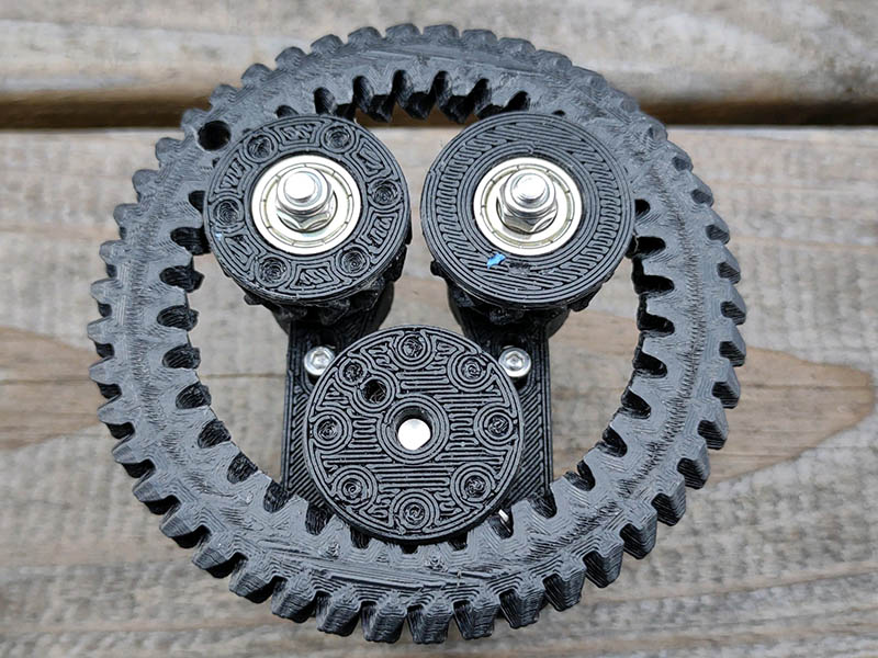
I ran into a couple of problems with this yesterday. First off, the inner ring gear needed to be opposite direction of outer ring. I had that correct early on, but somewhere along the way I changed it. Anyway, that was an easy fix. I chamfered the outside of the outer ring to cut down on overhang when I get around to printing the wheels. I printed only the part of the plate that had the inner gears for test fitting which showed a couple of things to fix. The drive gear needs to be smaller to get it to fit when putting on the Ferris wheel. I changed that from 16T to 14T, but 12T might be a better choice. There also needs to be an access hole in the Ferris wheel to be able to adjust the bottom 2 M3 motor mount screws. I just drilled one in for testing. Another problem I see is when I attach it to final plate with the wheels, the idler gears & drive gear will need to move the same amount & I don’t think a slotted hole for the idler bearings would work. In order to do that, I will need something similar to that test plate added to the outside of the main plate. I will try slots on the test plate 1st but am thinking the bearings might slip in them over time. Not sure how well that will all fit together, but I have not given up yet.
The gearing feels smooth rolling it around. Might make a nice fidget if it doesn’t work out for the plotter. Here is what the test print assembly looks like.
This Ferris wheel idea was starting to give me too much of a headache & was no longer fun, so I have shelved that idea again.
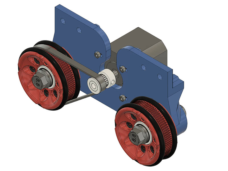
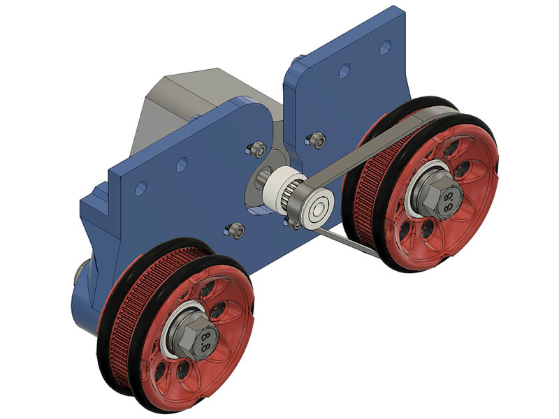
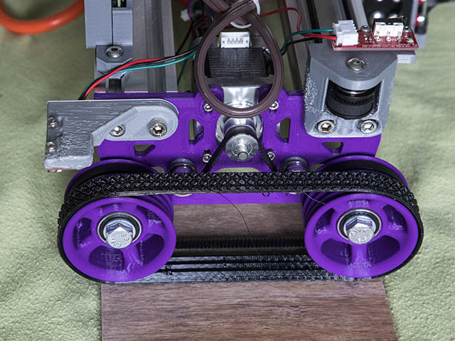
I am moving on to the idea of driving just one of the wheels on each side. I think one or more folks mentioned this method during my original design. I ordered 3 belt sizes, 220mm, 230mm & 240mm. Looks like I really need 240mm length to mount the motor centered but got a shorter lengths in case I want to try a shorter belt path. Would shortening the belt travel length 10-20mm make much difference in performance or accuracy? I will have to angle the motor if I use the 220mm length belt unless I change that plate design more. This might be a good opportunity to redraw this plate in FreeCAD. One thing that is a little aggravating in FreeCAD is that all the geometry needs to be tied down. Fusion 360 is more forgiving with this & sometimes quite difficult to get all the geometry tied down in Fusion 360.
This design would allow anyone that built the previous version to use all the previous parts except the 2-wheel plates and cut out all the hardware for the 4 idler bearings. You would also need a different size belt, but that is yet be determined. Here is my 1st draft of using the single wheel drive. Will be interesting to see if this has better repeatable accuracy than previous version. Looking at a commercial diode laser design (ortur laser master 2), I see they tie the motors on each side together with a smooth rod. Guess they are only using 1 motor to drive that axis though. I wonder if that would benefit this design? The only way I see to do that is to have a 3d print drive gear with 2 sets of teeth for 2 belts. The other belt would be quite a bit shorter (probably around 100mm length) connected below or above the motor to a geared coupling attached to the rod on each end. I will have to draw something up to see how it looks.