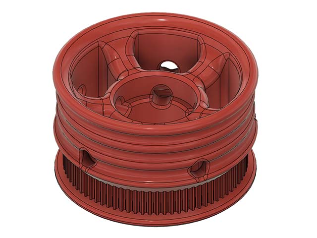
Since I’m using the 60mm skate wheels I had to do my 78-tooth pulley independently. I found an Openscad parametric design to create my basic STL… and then used Tinkercad to make slight adjustments. [I’m using STEP now.]
However @springer, over on the FT forum, piped up this morning and questioned why I had removed the wheel bearings and was relying on the bearings in the endplate to handle the cantilevered load. I told him I knew that wasn’t the best way but was just trying to keep it simple… and felt that I could get away with it because of the light loading.
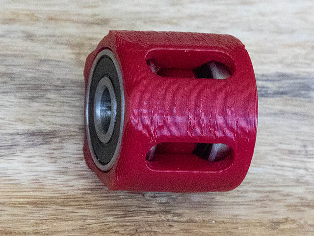
But it got me thinking… and I started looking at my printed sprocket part again. I decided a 608 bearing could easily be housed in the sprocket section and the outer filler hub replaced with the original bearing. So I made the test part (I used 22.2mm for the bearing pocket diameter) and now both bearings are back in place in the wheel and the endplate can be modified to provide a rigid axle attachment. [I’ve been meaning to ask… you have wheel bearings AND endplate bearings. What is the reasoning for having both?]
There is a ripple effect, of course. A couple of parts will need to be modified and re-printed… and a number of new SPACERS will be required. But, hey! Nobody ever said it’d be easy to stay on the “straight and narrow”…
Seemed like I needed them there. I initially tried just using 1 bearing on the plate, but 2 worked better. I am using 2 washers between the wheel bearings & the endplate bearings. If I didn’t have the bearings on the endplate wouldn’t the washers rub against the plastic endplate or is there another way to do this I am not seeing?
nothing has to rotate except the outer races of the two wheel bearing. The axle could be solidly fixed, or just pass through, a solid section of the endplate, rendering the two bearings in the endplate unnecessary. Without those bearings and just a fixed axle sticking out of the plastic, the double washers are just a spacer (also non-rotating) between the inner race of the inside wheel bearing and endplate plastic… no relative movement between them. There should be a bearing spacer inside the wheel, between the bearings’ inner races, and finally the outer wheel bearing. Again, nothing needs to rotate except the wheel and the outer races of the wheel bearings. An no washer in your diagram should touch a bearing’s outer race… the washers/spacers/axle and inner races are all stationary.
It’s very similar to an automobile’s wheel and wheel bearings… fixed axle in intimate contact with wheel bearings’ inner races and only the bearings’ outer races turn with the wheel.
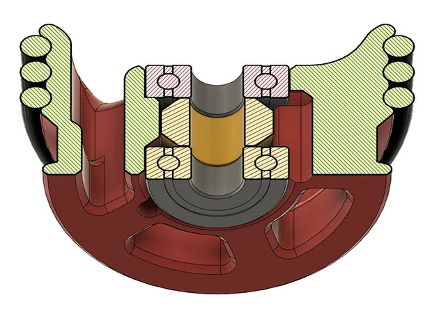
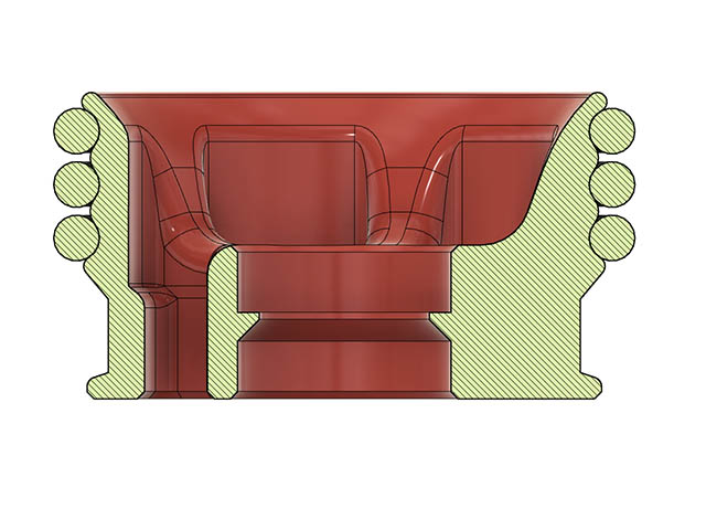
I see what you mean now. That would simplify the end plate & cut down on the number of bearings also. I do have the washers so they do not touch the outer part of the bearing. I will print a test cylinder the depth of the endplate tomorrow to make sure that will work. Thanks for straightening out my logic there. Since I have to reprint the wheels, I am changing them a little more. Currently there is 10.75mm space between bearings in wheels & I am going to make that 3mm like I had on the end plates. The O-rings are offset out from the bearings this way, but it is not a lot of weight on this seems like it might be ok. I might try just using 2 O-Rings as I originally was doing. Here is what it looks like so far in section view.
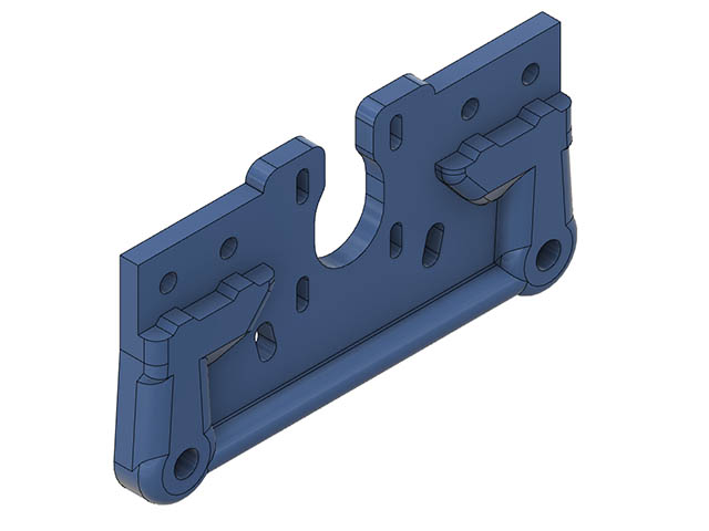
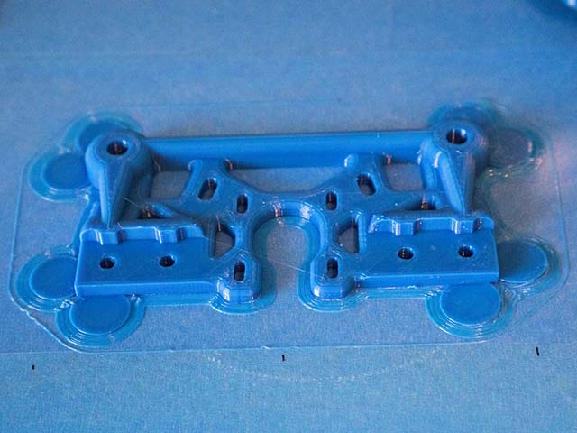
I really appreciate you pulling me out of my stuck train of thought. Thinking about that in the night it is funny how I never saw that before. My 3d printer with the openbuild wheels is bolted right to the carriage plate so it is obvious to me now that it will work & I don’t need to print a test print for that. I redid the wheel plate design this morning & cut out 25% of the volume & looks like it should still be strong enough. The wheel mounts & V2040 supports are now 12mm thick. They used to be 17mm & 20mm thick. With taking the bearings out, this plate could easily be cut out of Aluminum to make it really strong. The timeline on the fusion 360 file is also a lot simpler. It went from 37 entries to 16. Think I am not going to shorten the gap between the wheel bearings. Seems like the o-rings might wear more even with the light load. 22.4mm for bearings was still slightly loose, so looks like 22.3mm will be my optimal. You have a really good tolerance on your printer with 22.2mm. I have to do some more test prints on my wheel spacers. They are still just a little off.
I have printed some 6mm plates on my new printer build. They are suprisingly strong with enough perimeters and infill. You are talking about moving a pen, not mill steel. I wonder if 6mm at 60% infill would be as strong as 12mm at 30% infill. That’s what always gets me about 3D printing.
I have printed 6mm X carriages for my 3d printer at 60%, but without that ledge between the bolts it was not strong enough for me. That was also before I started using more perimeters to make it stronger. I have started using 4 perimeters instead of 3 to also make it stronger after watching CNC Kitchen’s video on the subject.
I’m thrilled those changes are working out for you… and simplifying things in the process.
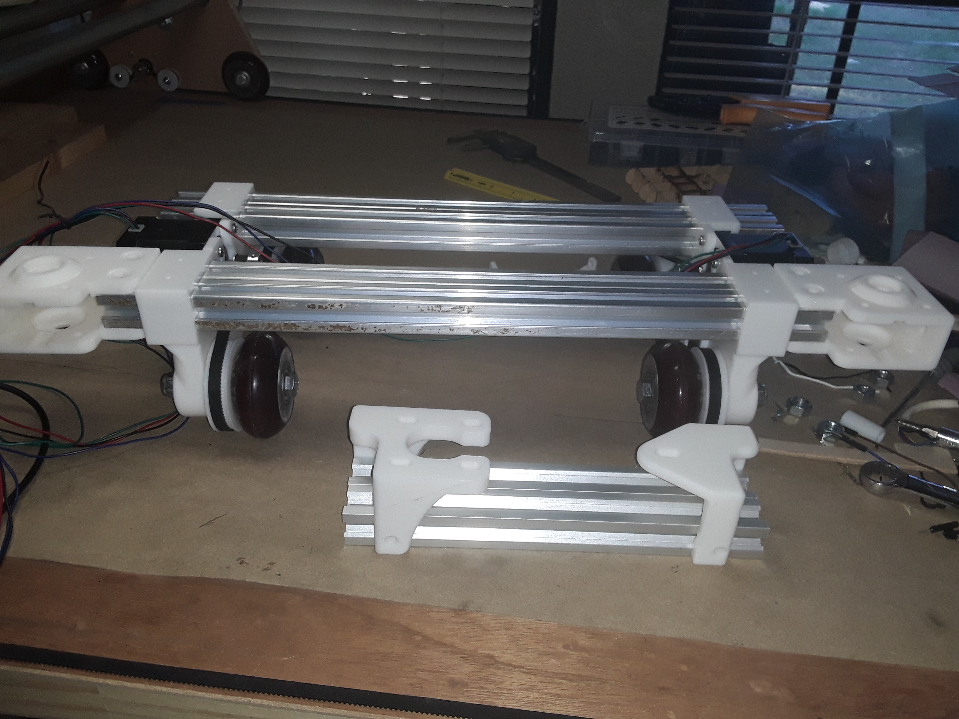
I’m also looking at these same relative parts and, short of modifying and re-printing my endplates yet, I’ve patched together a wheels/bearings setup that seems workable for now.
I’ve got the wheel bearings back in place (where they belong), with a new bearing spacer…
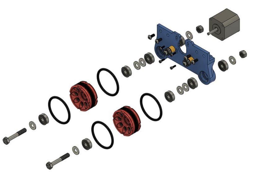
I’m probably going to keep the “beef” in my endplates… to provide solid support and alignment for the extrusions and wheel axles. I’m also wondering if I might be able to use Openbuild’s mini-V linear actuator “verbatim”… by allowing the 2040 rail/axis to extend sufficiently to allow the motor and idler mounts/housings to sit outside the wheels/workarea. I’d also have to remove the front “notch” where the extrusion passes-through the endplate to provide clearance for the belt to pass through.
I think I’ll go ahead and print a set of those linear actuator parts… as this seem like it could be handy at some point down the road, regardless. I’ve already got your motor/idler supports and carriage printed and can use those if the linear actuator idea doesn’t pan out.
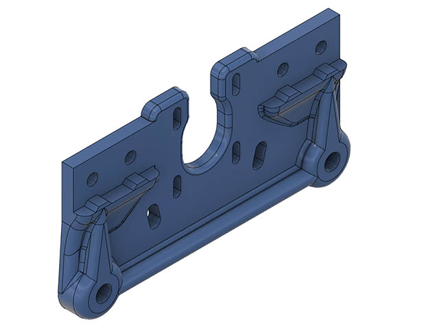
After reading your comment, I looked at taking more of the plastic out since those ledges probably do not need to be as thick as I had them. The bottom ledge between wheel mounts I changed from 10mm to 8mm. The ledge between each wheel & bottom 2040 support I made 9-14mm thinner & 32% less material than original design. I am going to use PETG for the end plates so will use 6 perimeters as suggested by Barry I believe in other thread. I probably won’t print those end plates yet in case someone gives me some other comments I had not considered. I need to fix the wheels 1st anyway.
dkj4linux, I can give you the step file of my modified plate if you want? Look forward to seeing your 3d printed actuator idea if it works for you.
I think they’re too big and clunky – maybe not so bad with full-width/size setup – and I think there will be belt clearance issues. Then I happened to look across the room at my TimSavX2 hot-wire machine and I think it has a tower axis setup that might work well. I’ve printing up a motor mount now…
I Initially tried running the belt thru the 2040 V-slot, but seemed like a tight tolerance to me & the belt would rub the side of the V-slot. I know it is done quite a bit, so with the right setup it should work. I was using 16T timing pulley at the time & really needed a 20T.
Looks like my endplate prints are staying flat now. This is the 1st print which started to pull up on the V-slot corners & 2nd print stayed really flat. I printed this endplate with 4 perimters & only 30% gyroid. I think once the V-slot & motor is connected it will be quite solid.
Since I am printing the wheel with tighter tolerance (22.3mm for 22mm bearings), I wanted to be able to get those bearings out if I wanted to. I think these 5mm access holes should work & not cause any problems in the design.
I don’t think my wife would appreciate me doing that & also those bearings have some sort of plastic or rubber seal around them that would probably also melt.
In order to know better what height spacer to use between the wheel bearings I added slots that my caliper would fit in. Even though the design is 10.75mm between them, it comes out to 10.5mm so this was a useful test print. That was a lot better than trial & error printing to determine what the height should be. Here is an image with the spacer in place.
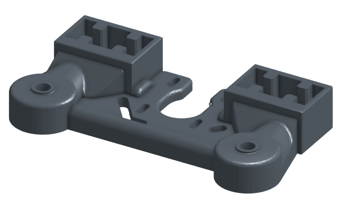
My 1st new wheel print failed for some reason half hour into the print, so I decided to look at an alternative to the bearing eject holes. Think I came up with a better idea than the side mounts. I made 2-3.5mm slotted holes thru the bottom which should give me enough room to insert an allen wrench in. Coming from the bottom & not the side they are also not visible when assembled.
I also realized after looking at this section why those bearing spacers needed to be shorter. With the tapered resting spot for bottom bearing and rounded edge of bearing it will rest a little higher in the wheel. I have the bottom bearing designed to sit 1mm beyond the bottom of the wheel, but measures .75mm after inserted. That measurement verifies the spacer size as it did come out .25mm shorter.
Plotter test was much better with the wheel spacers than without them. It is still not perfect yet. I am about 3.5mm off at end of plot from where it started. The best I had before was about 12mm. I will reprint the wheel endplates with higher infill to see if that helps. it has a little flex in them at 4 perimeters & 30% gyroid infill. A friend suggested using a yoga mat for the rolling the plotter on, but it was not as accurate as rolling on the vinyl cutting board. Here is the test video running at 1800mm/min.
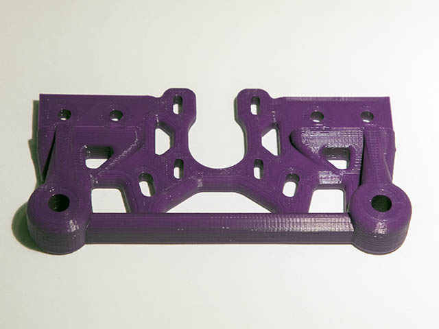
My wife likes purple, so I have some purple filament on hand now. This has no flex at all in it now. I printed with 6 perimeters & 50% gyroid & .24mm layer height. Printing 2nd plate now. If it is still a little off after this change, I will suck it up and make the wheel bearings press fit tight with no access holes. I could always drill out the plastic beside them if I needed to move the bearings to a newer design later. That should be the only other thing I can adjust without adding a wheel guide.
I’m playing with similar “drift” issues right now… it’s not terrible but also not perfect. I think that both tractors/trucks must run EXACTLY PARALLEL to each other… i.e. any “toe-in” or “toe-out” between them will cause “drifting”. My gut feeling is that since our tractors/trucks are not constrained to always follow a fixed path – rail or guide – drift is always going to be an issue… and for any real “precision” a guide of some sort is going to be necessary. I wonder then … should it be called “track plotter”?


 .
.
 Only thing left would be the bearing and a pile of PLA goo.