Could you use the arc feature to ‘navigate’ paper/surfaces wider than the wheelbase? The idea would be print a column, ‘arc’ over to the next column, print it, lather, rinse, repeat… and now the rolling plotter can handle infinitely-large sheets of paper!
Or parking lots
1 Like
I did test the arc idea on the 1st build. Take a look at Rolling Plotter build - #88 by geodave
1 Like
That’s the one I was replying to - apologies, I am new here and feel like I’m catching up on years of missed wonder as my 3D printer works on my new Primo core!
2 Likes
No problem. Enjoy your endless possibilities of printing.
2 Likes
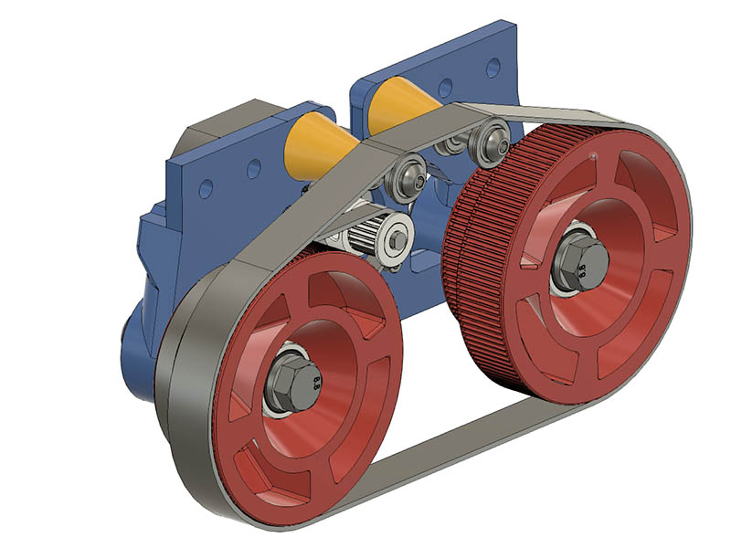
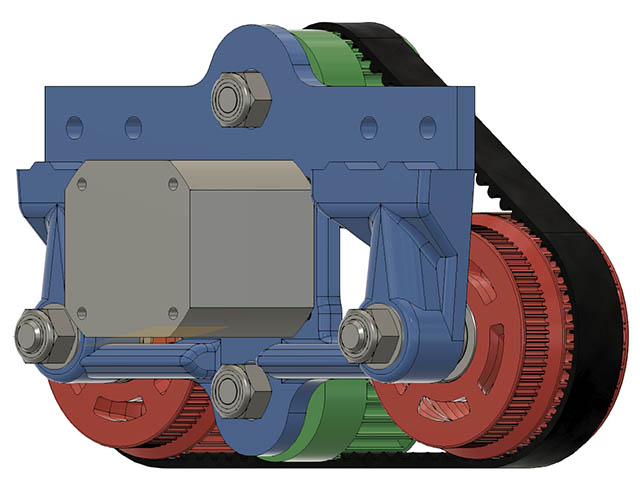
I woke up with the idea to use GT2 closed loop belt for the tires instead of O-rings. It seems like those belts would give pretty good grip & I can get 15mm wide belts for the lengths I need. I did a 1st draft of what it might look like to see if it looked reasonable. Probably only need one idler bearing on center above the motor if I close up the motor mount opening at the top. The wheels need some more work before I would print them.
See what you think. I might use the same bearings for the wheels for the idler to give it more support. I currently have the Drive gearing at 88T & the wheel track gearing at 125T which gives me a 79mm outside diameter wheel versus the 59mm diameter before.
3 Likes
It’s a tank! That looks good. I wonder if you could spray the outsides of the belts with something a bit grippier, or even paint them with latex?
Or maybe glue a bit of bicycle inner tube to the outside of the belt.
Those are interesting ideas. Paint or spray might wear off over time.
2 Likes
Maybe that kind of mounting spray:
https://www.3m.com/3M/en_US/p/d/b40069398/
My guess is this whole assembly doesn’t weigh too much. I would make an area to add some sort of weight to it (bricks, ingots, toddlers, etc.) so that gravity keeps it grippy.
3 Likes
I had a thought along those lines also of adding some weight to it. Might cut into acceleration some, but this generally does not move fast anyway.
@olijouve I will keep that idea in mind of the spray, but will try just the raw belt to start with. If I run this on the floor, I would be concerned that stuff might come off & stick to the floor.
I am still trying to decide on which belts to get. I currently like this one if going with GT2 belt for a 500mm length, Gktools C-24 3d Printer Gt2 15mm Closed Loop Rubber 2gt Timing Belt Width 15mm Length 320 350 400 420 436 500 600 610 710 760mm - Transmission Belts - AliExpress
But kind of like the HTD 5mm in 475mm length. It is over twice a thick as the GT2 belt. 3D Printer HTD 5M Closed Loop Rubber Timing Belt 475 500 525 550 595 600 700 800 900 1000mm Width 15mm HTD 3M|Transmission Belts| - AliExpress
I should be able to design around either one. I will have to redraw the tooth profile for this, but looks straight forward.
Here is another HTD 5mm belt on ebay which is a little more expensive but has a lot more size options.
HTD 5M Timing Belt 5mm Pitch 15-20mm Wide - Select 180mm to 495mm | eBay
Are there any other good belt options to use? GT2 seems to be the easiest to find in more sizes. I have some spare GT2-444mm length 6mm width closed loop belt I might think about testing 2 of those side by side since I have them.
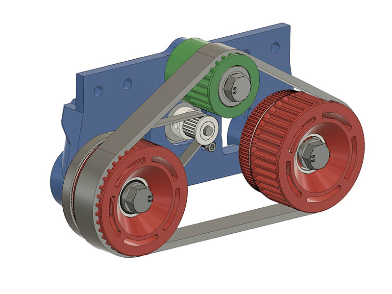
I redrew the wheels & idler bearing using HTD-5 belt profiles. As you can see the belt is considerable thicker. I am now using the same 608-2RS bearings in the idler as I am in the wheels. I will test print the geared idler tomorrow to make sure it spins. The teeth are also a lot bigger with the HTD-5. The HTD-5 on the wheels have 38T each & the idler has 22T. I am at around 435mm belt length now & just found this source for that size, so maybe I will not have to change the number of teeth. Powge Htd 5m Timing Belt C=430/435/440/445 Width 15/20/25mm Teeth 86 87 88 89 Htd5m Synchronous Belt 430-5m 435-5m 440-5m 445-5m - Transmission Belts - AliExpress
Here is my latest drawing. It is starting to look reasonable now.
1 Like
Not sure I calculated this belt length correctly but can fix it if I am in error by shortening the wheel spacing from 120mm to 110mm. I was using the inside dimension of the belt for the length & looks like it should be the pitch diameter. The length comes out to about 453 using the pitch diameter & my current spacing. I discovered this problem after modeling the 440mm belt length as it fit on this machine.
I initially drew each tooth in a sketch copying them along the straight lines & pulling the arced ones from the other 2 models I had already drawn. The ends did not come out quite right. On my 2nd approach, which was a lot easier, I realized my problem was not using the Pitch diameter. I found the fusion 360 command to copy a body along a path.
The length of the belt along the Pitch length is 439.9897mm. Close as I could get it to 440 by just a little trial and error of adjusting the top idler location.
Here are screen shots showing my method for drawing the belt.

Draw one tooth at the start of the bottom straight line.

Extrude it up 15mm which is the width of my belt.
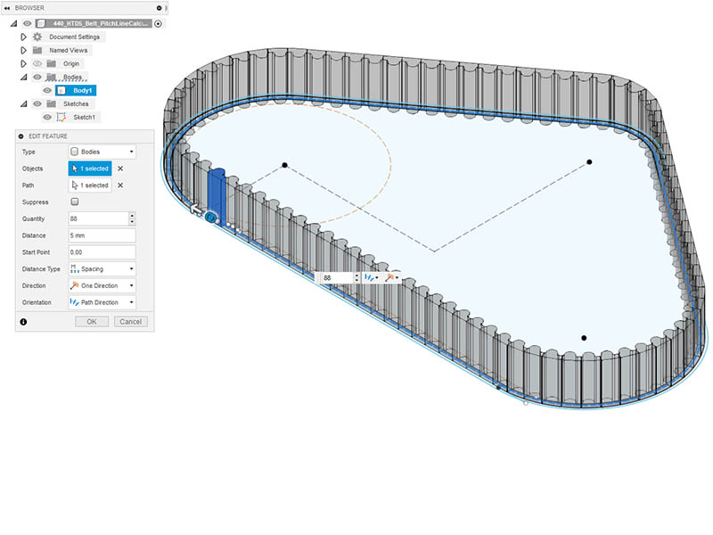
Create a Pattern along a path (pitch sketch line). I had to play with this command some. Initially setting Distance type to extent & typing in 440. Then change it back to Spacing. The Quantity option did not show up until I did it this way. I used 5mm for distance and 88 for quantity since this has 88 teeth (88 * 5mm =440mm).
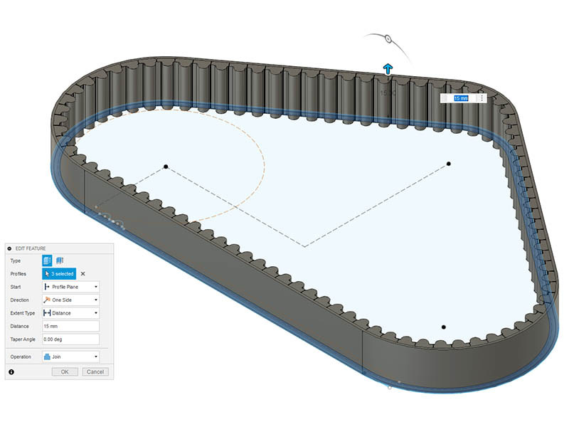
I extruded the outer ring of the belt to fill in the gaps of the 88 teeth. I added wider than needed initially because it had some artifacts along the curves otherwise
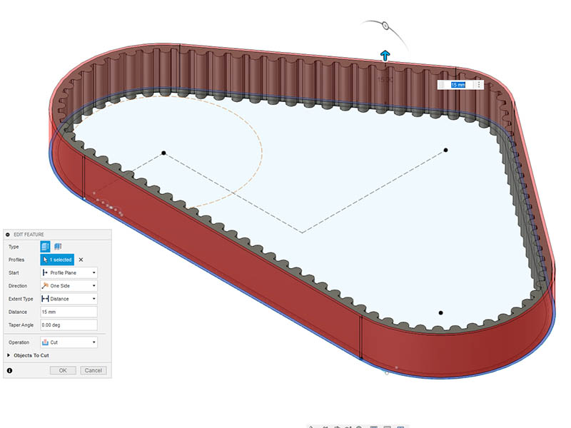
I then cut the outside of the belt to correct width.
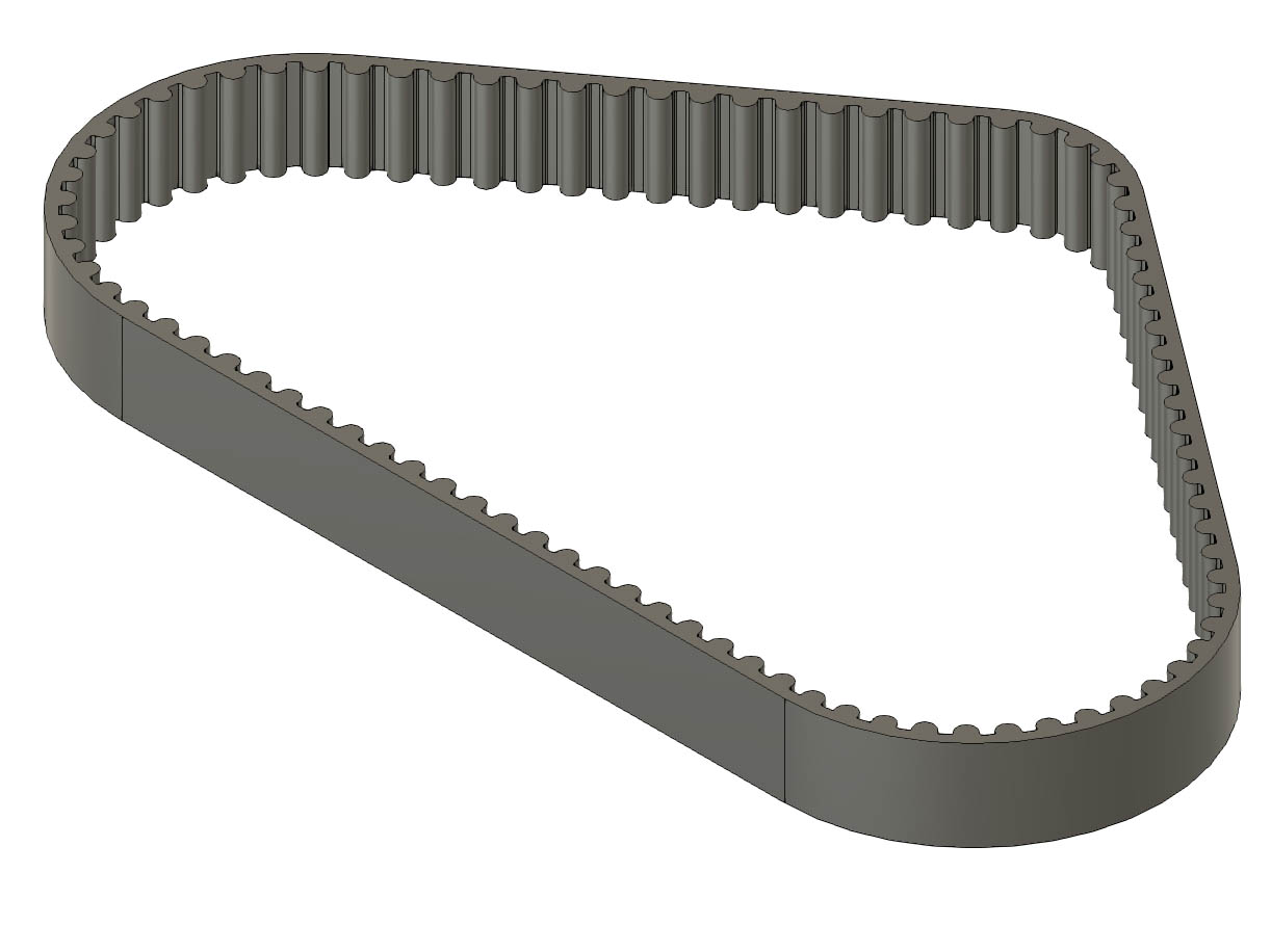
Here is the finished belt

Here is my belt drawn along the pitch line with the dimensions I used. With only a little more trial and error, I changed the idler offset to 56.989 mm which gave me 440.0004mm length.
2 Likes
Nice. Is the idler pulley mounted in a groove so you can push it in/out to adjust tension on the belt?
Or an eccentric spacer like on 2020 gantry plates.
Yes, I have 6mm of vertical movement & center of the slot is the length of the belt.
@Strider_Matic I have using an M8 bolt for the idler gear, so the eccentrics would not work.
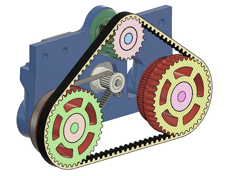
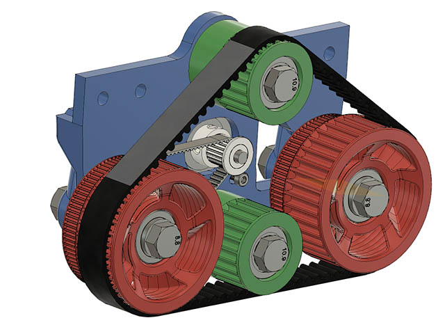
I adjusted the wheel plate to use 110mm spacing & modeled the belts. Looks like it fits together better now. Here is a section cut with the belt track & matching gears.
3 Likes
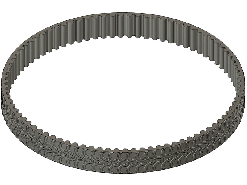
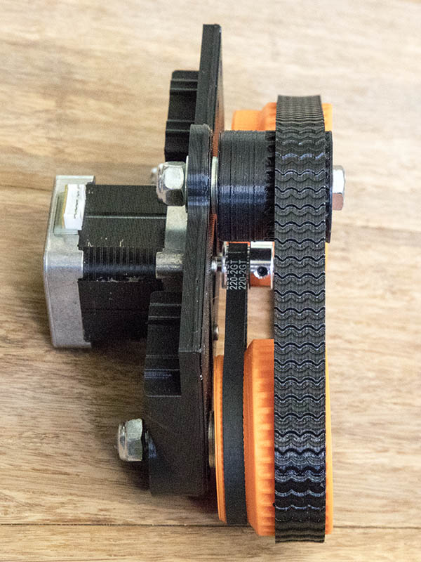
I got my GT2 closed loop timing belts yesterday & should get the HTD5 Belt closed loop belt by the end of next week. Meanwhile, thought I would see if my printer would cooperate & print TPU. I designed this belt to print adding some tread to the outside surface. I made it 86T instead of 88T since the TPU will stretch a little from my past experience with it.
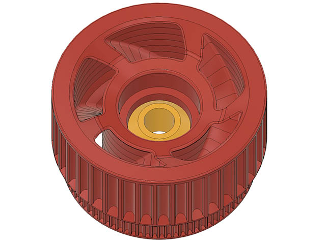
I initially had these wheels cut with a profile revolved 54 degrees & then repeated 5 times around the wheel which works pretty well, but I wanted them to have a little more character. Having the cutout spiral down seemed like a good choice to work with. I am using Fusion 360 for this & first tried lofting the bottom to the top with a 72-degree (360 /5) difference between them but could not get a rail guide to work along that curved angle. I then came up with the idea to use my original cut profile & slice it every 3mm high (10 layers total) & copy that cut to another sketch & rotate each level in 7.2 degrees increments. I was then able to loft each 2 sketches that were 3mm Z difference & 7.2-degree rotational difference. It was not too much trouble & think it came out pretty good. Seems like it should give it better structure as well.
I had to increase the GT2 drive tooth count on the wheels from 80T to 84T. I am also trying 85T since the motor is close to far end of center tightened. I am not sure why the calculations did not work for that, but easy enough to adjust for at this point (I did use the pitch diameters for the calcs). This makes me wonder if the HTD5 track belt is calculated correctly. I will not print anymore until I test fit that belt when it comes in.
[Edit] I found my problem. I have 3 different size GT2 closed loop belt & picked up the 230mm length instead of the 220mm length. The 220mm length does fit, so that makes me feel better about my calculations.
I have not printed TPU tread yet but did change it from an embossed tread to a debossed tread. I learned a new term today when I was googling embossed. I had not heard the term debossed before. I am not sure whether embossed or debossed would work better. It might depend on the tread design?
I made a couple of other changes to the wheel plate. I added in an optional idler wheel at the bottom so track would keep the belt in more contact with the ground between the wheels. There is a 8mm slot adjustment for that idler at the I can always leave that idler wheel out if not needed. I am not sure I really need the bearings for the wheels in the plate. They do give the wheels more support but am going to try it without them. I won’t print this new version until I test the HTD5 belt. Here is what that plate looks like now.
4 Likes
I printed a belt out of TPU today. Since it is dialed in, I started printing another one in case I want to test it before real belt comes in. This took about 2 hours 40 minutes to print at 30 mm/Sec. I have a few blobs on the inside of the belt to clean up a little still. I had to stretch it some to fit since it is essentially 10mm shorter than what I designed for. I did not want to make it the same length since I remembered it stresses a little.


10 Likes