Ohhhh now i want direct drive. That would make tank track or tires or… Nice!!
That looks like you are having a lot of fun now. Good work on that belt, I would not have known how to approach that.
Looking good! I’m pondering making an rc tank, and printing the belts would be super. What rating does this TPU have?
I made one of these and it was really fun.
It can use Lego tracks if you have trouble with the tpu
It has a shore hardness of 95A & here is the link for it. Black TPU 3D printer filament 1.75 mm 1 kg 2.2 lbs - ZYLtech Engineering, LLC
I also have some yellow eSun eLastic TPE with a hardness of 85A, but was unable to print that before. I might have to try that one again as it doesn’t seem like 85 is that much softer than 95 & probably did not have my printer tuned as well for it back then. Clearance eSUN eLastic TPE 85A Flexible Filament 1.75mm – INTSERVO 3D Printing Store
so I know some people say they print tpu with bowden, do you have direct drive, or bowden?
I have a direct drive titan extruder. I have problems using a bowden extruder with just normal plastic. I set the heatbed temperature to 60C for the TPU & in PrusaSlicer set the Z offset to -.1with the bed trammed with a .1mm feeler gauge. I usually use 45C for the bed with eSun PLA+ which is my goto filament. This yellow TPE is really smushy & wasn’t sure I could get it pushed down thru the extruder, but I am at 4 layers so far so it will probably finish. If I get past 1st layer with this type of filament it usually prints the rest ok.
This Yellow TPE I have had since 11/2017 in a ziplock bag.
Thanks. It all comes about by trial & error & suggestions from folks in this forum & openbuilds forum.
Just quick PSA. Don’t print TPU on a bed with a PEI surface. Put tape down and adjust your Z zero. It will ruin your bed because it bonds to the PEI.
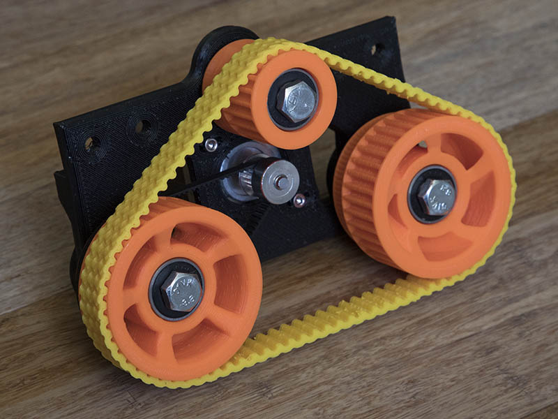
I like the feel of this one better than the other. Seems a little more grippy which is what I am looking for, so am going to print another one. It also adds some more color to the plotter.
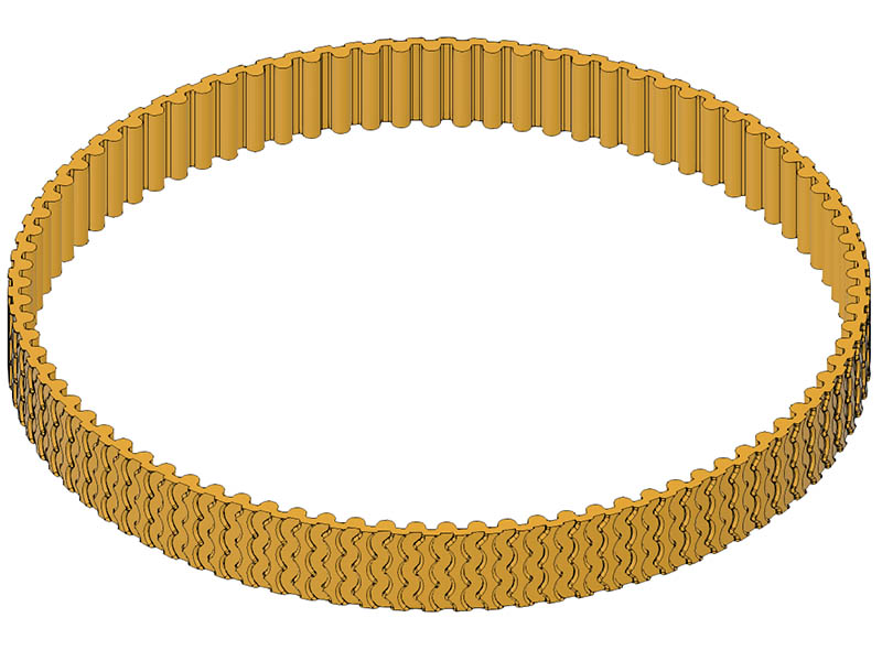
Here is a better view of what the tread design looks like. I added a 0.5mm round to the outside edges. In retrospect, it might have been better not to add the rounds to make it a rougher grip. Not sure I want to print another 2.5 hour print of it to test that idea. Maybe I will cut out a quarter slice or less for a test print to see what it feels like.
Good to know. I print on either painter’s tape or bare borosilicate glass and sometimes add glue stick.
Yeah, I do glass. On my MP3DP i have a glass plate with pei on one side (been replaced once  ). I just flip the plate when i print TPU.
This project looks really fun! It looks like you could double your track width which would give you more contact surface area if you still have traction issues. That would also hide/cover your drive belt. Downside is that it would also double your print time for each track. Thanks for sharing.
Thanks for the suggestion. I could make it wider on the outside, but not much on the inside unless I overhang it. After your suggestion, I looked to see if I had room to make a cavity for the drive belt to fit in but would only have about 1.5mm of wall thickness. If I made the outside wheels a bigger diameter it could be done but would be longer prints for the 4 wheels also. It would probably have to change the number of teeth from 38 to 44 on the wheels which would change the outside diameter from 59.34 to 68.89mm. This should give me about 4mm wall thickness. It is worth considering but will follow thru with this size 1st to see how well it works. I was initially matching the 15mm width belt I ordered. Those belts do come in 20mm & 25mm widths but seemed like 15 would be sufficient.
I teste printed a 60-degree sliver of this current belt without the rounding of the tread & it is actually rougher with the rounding.
I’m not sure how a cavity would work, since the drive belt still has to leave radially. But the wheel could be ‘hourglass’ shaped with the drive teeth in the middle and tire teeth on both sides. The motor pulley would have to extend a bit more for the drive belt to be in the middle, and then a wide tire could ride over top of the drive belt (with tire unsupported in the middle of the wheel).
I’m not sure if it’s “better” but it would look cool. I’m guessing it’s probably worse for putting a larger moment on the wheels due to the longer distance between the drive belt and the support.
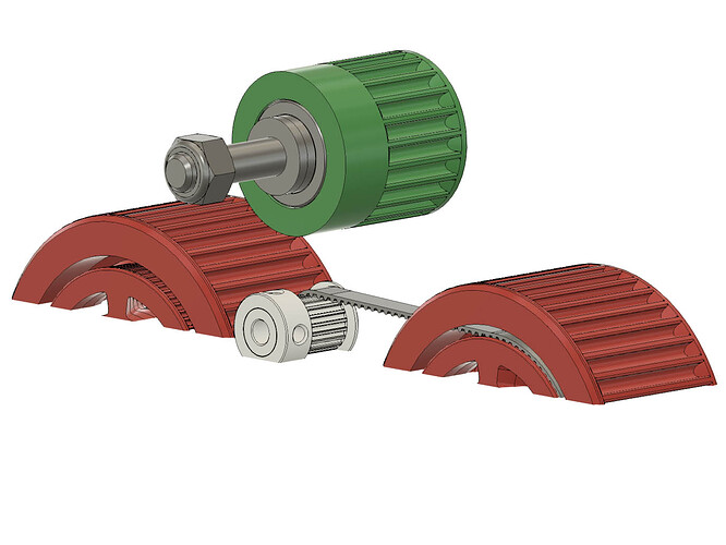
Thanks. I had to draw it up to see the problem. For some reason, my mind could not see it. Might have been the couple of beers I had tonight, at least that is my excuse. That drive belt would go thru the wall of the wheel. Interesting exercise all the same.
Here is a screen shot in case anyone else has a problem seeing this.
The hourglass is an interesting idea & will ponder that. Not sure I have enough room to move the drive pulley out far enough to get another belt in there next to the wheel plate. It would probably be smaller than 15mm wide anyway.
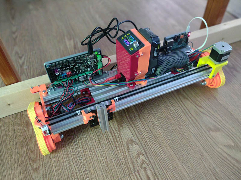
I am slowly putting this all together. The PS for this will be portable using ryobi 18V batteries. Here is the step-down PS I use for the batteries. Rd Dps5005 Communication Constant Dc - Dc Voltage Current Step-down Power Supply Module Buck Voltage Converter Voltmeter 50v 5a - Multimeters - AliExpress
I am thinking of putting a switch on this since when I plug the battery in, the display lights up. I will start off using the MKS 8bit board with raspberry pi for wireless for initial testing, since that is how I did it a couple of years ago. I hope to get the DLC32 board working on this which would take the pi out of the mix. the HTD5 belt I ordered is a little loose, so if I use that the idler bearing gear will have to be a little bigger or the wheels.
Now I want to build one of those with a laser…
Will have to see how repeatable accuracy it has this time around. The previous design was not accurate enough for a laser unless you modified it to something like @dkj4linux did.
I got all the parts working yesterday & will do a test plot today. It was a bit of a struggle getting the newest klipper firmware to work. The author had turned off a couple of settings (They seemed to be redundant settings anyway) I had in my config file & changed the naming of the pins. I started to just add the alias info into bottom of printer.cfg file from the info on this page klipper/sample-aliases.cfg at master · Klipper3d/klipper · GitHub , but then just copied the pin info from a more updated example file. Eventually I hope to just use the DLC32 board and make this an even simpler setup.
When I first tested the movement, the motors just made a noise & did not move. Thought it might be the motor wires being in wrong pins as I had seen that before (and it did turn out to be that), but wasn’t sure I had the firmware correct, so I went back to my known good configuration from 2 years ago. That was a good idea since I didn’t have a copy of the old config.yaml file for octoprint and macros I had used. I do wish I had an 8GB microSD card for this instead of the 16GB card as it would taken half the time to restore it. These Industrial grade sandisk MicroSD Class 10 cards look like they might be worth having. https://www.amazon.com/SanDisk-Industrial-MicroSD-SDSDQAF3-008G-I-Adapter/dp/B07BZ5SY18 I swapped the motor wires for some others I had & they did work. I really need to try & move those wires to the correct pins, so I don’t do that again.
I am using a little RAVPower 6700mAH External battery to power the Pi 3B+ 5V supply & new version of octoprint gave a warning of underrated power. the charger has a 2.4A usb connector, but wonder if the cable connected is not rated that high? Anyway it works, but might be throttling the CPU a little. Interesting enough today, I am not getting that warning. The step down PS I bumped up the voltage from 12.00v to 12.07v as I saw the voltage slipping below 12v. I remembered that my 3d printer PS was set to something like 12.06v. I really like this portable PS idea that I found a couple of years ago. I will have to create a different power cable to use with the DLC32 board.
If I used this setup outside my WiFi network, I would probably use the V1Pi that @jeffeb3 created Dip a toe in the pi, V1Pi. | V1 Engineering Inc or take a shot at this tutorial. Create a Wi-Fi hotspot in less than 10 minutes with Pi Raspberry! – Howto Raspberry Pi
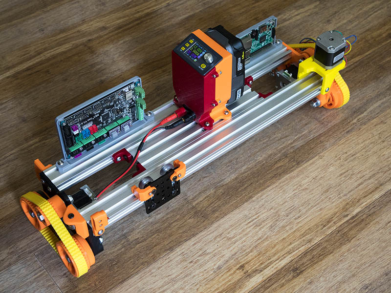
Here is a photo of it all together except for servo not hooked up.
