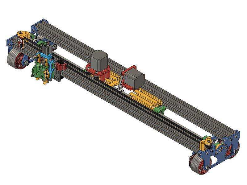
2 years of refinements looks good!
I still have a few things to do before I can finalize this. I was realizing yesterday that I need a little more space between the carriage motor and the battery power supply. I could use 2 - 2060x250mm, but realized 3d plastic ones should be sufficient since they don’t support much weight. In doing so I am able to incorporate the angle connectors between these & the 2040 & cut out the number of 3d printed parts. I can still use the real 2060s if this doesn’t work, but also cuts having to buy a 2060 v-slot.
1 Like
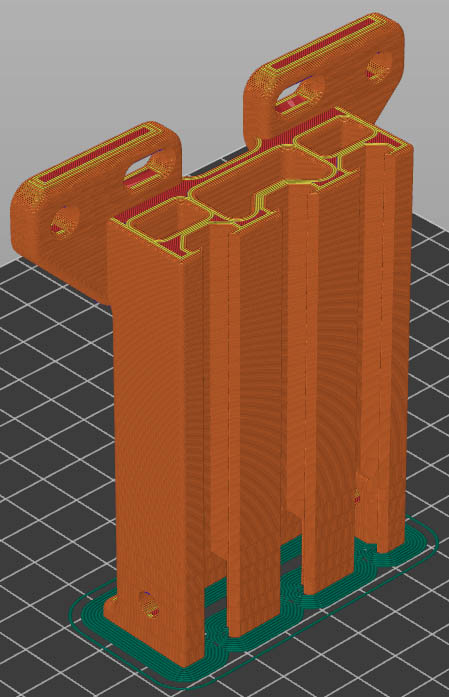
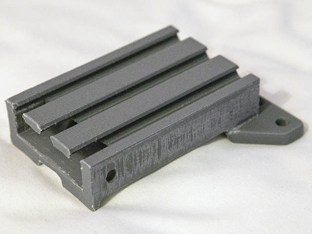
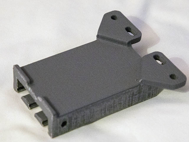
This came out quite well. I incorporated the 4 connections between this and the 2040s, thus saving printing 4 other parts. This did take 4 hours and 40 minutes to print with 5 perimeters, 50% infill & .12 - .28mm layer height adaptive with PrusaSlicer. On my short test print I did not have to file it any with the standard .2mm layer height. Seemed like the .28mm caused it to be slightly thicker. Only took a minute or so to file it though. It seems quite solid, so am going to back off the settings a little printing the 2nd one at 3 perimeters, 30% rectangular infill & .16-.24mm adaptive. This also should cut an hour off the print time. I added a little bit of plastic to bottom back of the print for more surface area adhesion. That & the 5mm brim kept it on the build plate well. T-Nuts slide in well. I also took out the M5 end holes & just used channel holes to cut out plastic & possibly run any wires thru.
3 Likes
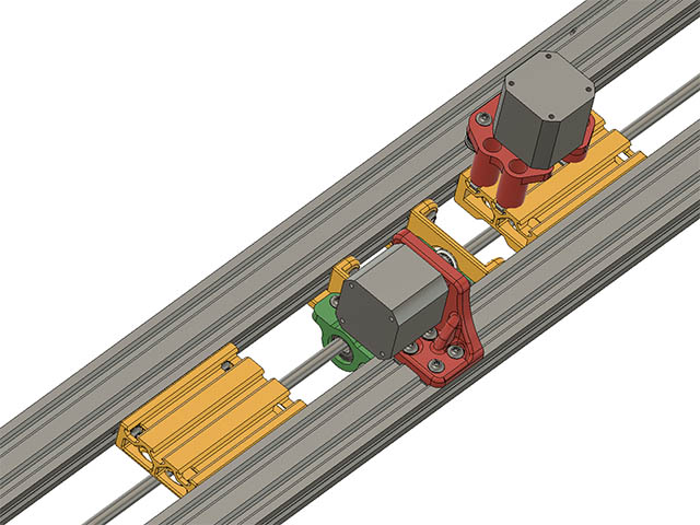
Almost there. While assembling the new 3d printed custom 2060 mounts I realized the bearings needed to be close to where the motor belt connects to the M8 smooth rod via that 20T gear pulley, otherwise it can flex that M8 rod too much. I redesigned the 2060s to use T-nuts & made a separate part for the idler bearing mounts. That way I can put them as close as possible to the motor gear.
Might could just use 1 bearing there, but 2 will give it support on both sides of that 20T gear pulley & that is what I have done on the outside wheel gears.
This should work better. Here is a view from underneath the plotter.
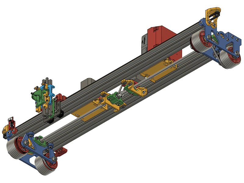
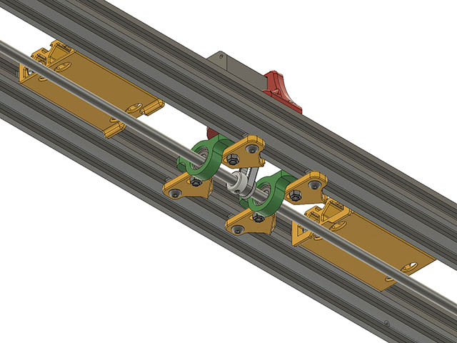
It feels pretty symmetrical now & am liking how this latest version is finally coming together. I did find one more change to the Wheel motor mount. Before I had it mounted with 2 M5 T-Nuts on the inside top & side. In order to get the other 608-2RS bearing as close to the drive gear, I moved all 4 mounting holes to the top. Might only need 3 mounting holes but left it at 4 for extra support. After I replace this part, I should be ready to put the carriage belt on & test run it. Here is a top & bottom view where that motor is. I can get the bearings even closer than what it is drawn but can visually see it better this way.
5 Likes
Here is the 1st movement test of this latest configuration.

6 Likes
I am working on the BOM for the final version & I have a question about tolerances on 608-2RS bearings. I have some of these bearings that are right at 8.0mm ID & some that measure 8.2mm ID. The problem I have is the ones with 8.0mm ID will work well in the wheels with the M8 or 5/16" bolts, but they are too tight a tolerance to fit on the M8 smooth rod I bought from zyltech. That rod measures exactly 8mm in diameter. The bearings with the 8.2mm ID are ABEC-5 rating I bought on eBay back in 2019. The ones with 8.0mm ID I bought from v1engineering for my MPCNC back in 2015. I was going to spec the ones I bought from eBay, but those are no longer available. Is there any way to tell what the actual ID is before buying them?
I also found some softer O-rings with a 70 Shore A rating on grainger, https://www.grainger.com/product/GRAINGER-APPROVED-O-Ring-328-1KLR8 . The ones I am using have a 90 Shore A rating which seems to relate the same rating TPU has. I am wondering if those softer ones would be better since they should give more surface area to the floor since they would squish more?
Already considered Gecko skin inspired tires The Stickiest *Non-Sticky* Substance - YouTube ? Some inventing and manufacturing may be required ![]()
1 Like
If the ID is 8.2, they are not ABEC-5 bearings, they are trash.
The problem with Amazon and I assume eBay is that the sellers are extremely price competitive, and they outright lie.
I bought some bearings on Amazon that were said to be sealed, yet they obviously were not.
These also had a bit of a crunchy feel to them but I can’t measure it or prove it.
Here’s a table I found that says that the inside bore for ABEC-5 bearings are allowed to be 5 microns undersize and they are not allowed to be oversize.
https://www.astbearings.com/bearing-tolerances-precision-levels.html
2 Likes
Thanks for the info. I figured they were probably not ABEC-5 by the price of them, but in my case, they worked better than the other bearings. I guess there is no real way to know what the inside diameter is actually going to be unless you buy them & measure them. Is there a tolerance for M8 rods? If I use 608-2RS bearings with an ID of 8mm, they won’t fit. Are M8 rods not designed to use these bearings? Seems like there needs to be like a 0.05 - 0.1mm difference for them to fit?
That Gecko skin is quite cool. Thanks for sharing that link.
Dude those are missing half the balls as well.
For automotive builds, there are a few ways thst we fit things with close tolerances
One of which is heat. For example in order to fit the wrist pins in my pistons, factory procedure is to put the pistons in a pot and boil them, then fit the room temperature pins through the piston and connecting rod.
While I don’t think I’d want to expose the bearings to boiling water, particularly when the sealed state of them is in question, I might put them in a water tight plastic bag and put that in hot water. A little heat will probably get you that tiny bit of extra tolerance that you need. Just be reasonably sure that you don’t need the bearings to slide back and forth afterwards. Put the rod in the freezer, or use an ice pack to increase your tolerances. (This might be enough with the bearings at room temperature, or maybe just a little warm, now that I think about it…)
You could also use a propane or butane torch, but that is likely to be a bit hard on the seals and any grease in the bearing. I think the more uniform and controlled application of heat with hot water is better. You could probably use hot oil, but then you could get hotter than the seal can take pretty easily, and cleaning the pan after is trouble.
If you need to change those bearings after, it may take a press to get them off of the rod.
The nice thing with that super close tolerance though is having the bearings stay in place under almost any usage, or, more like, not having to worry about axial shaft play. Even if it’s under high temperature usage, the shaft will expand too, keeping everything tight.
Note that you get nore rolling resistance if the center race on the bearing rotates on the shaft, so keeping that stationary is the best practice.
2 Likes
This is how they install the copper parts of a towerbell „beater“ (don‘t know the English word), really, really interesting and sounds like a great idea for parts that need to fit, never thought about adapting it for home use. ![]()
1 Like
Someone on a discord server recommended using an M8 leadscrew instead. Looks like an M8 leadscrew might be a better way to go rather than an M8 smooth rod. Those 8.0mm ID bearings will fit on my 3d printer’s leadscrew. Measuring that M8 rod with my calipers, seems like the one I have might be a shade over 8.0mm in diameter. I can get an M8x1000mm leadscrew from aliexpress for $25 or from zyltech for $23+shipping. Those are probably a better tolerance than the M8 smooth rod since they have to fit those standard leadscrew brass nuts. I will have to consider getting one of those, but probably get it from aliexpress. Seems like I might get better accuracy if the bearings on that axle are a tighter tolerance.
Actually, another option that same guy mentioned was to go to local hardware store with that bearing & gets some tubing to match it. Lowes has 5/16"x6’ threaded rod for around $7.50. that would probably work.
Mmmmm, sous vide bearings. Done perfectly!
1 Like
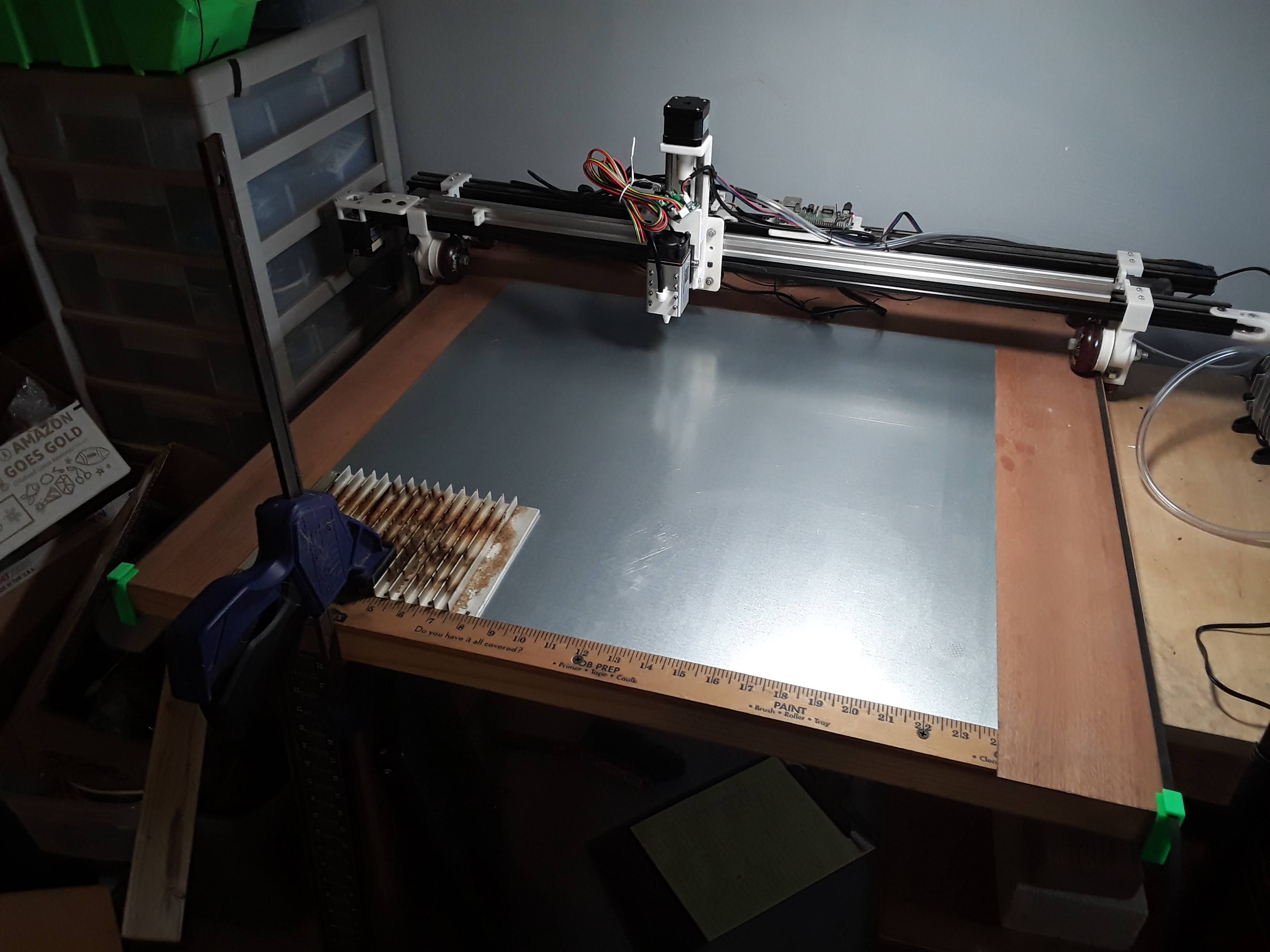
I finally uploaded the files & BOM for this current design. I probably need to add more details for this.
I also added an optional TPU printed tire to replace the 6 O-Rings on each wheel.
6 Likes
Speaking of rolling plotters… I just found this video of the SRWOR 10W self-propelled laser engraver. Just $700 and you can have one of your own! ![]()

A pretty interesting machine, he puts it through a few tests that highlight some of the same issues I saw with my “free-rolling” system before it morphed into the gantry for my now dismantled LowRider-inspired Foam Ripper. Once I belted it up ala LR and constrained it to the worksurface with small training wheels, it became a reasonably accurate and repeatable machine…
– David
3 Likes
Pretty interesting. It would be interesting to see what the wheels look like & drive system. Looking a the link for that machine, I find it hard to believe that got that one long image burn done with that machine. I won’t have time to look at that video link in detail until next week, but from what you said sounds like he had similar problems I did. I am thinking of ordering those other more squishy O-Rings next week as they seem like they would give me more surface area contact for better grip, but from @jamiek comments in the past that might not be my problem. For $12-$15 it seems like a worth while try.
1 Like
I finally watched all of that video. Looks like it is more accurate than my current setup. He said it was quite heavy, so maybe more weight on mine would help it. I ordered the 70A hardness O-rings today & should be able to pick them up Wednesday. I just remembered this morning I had a MKS DLC32 board I was going to try on this machine with FluidNC. I have not played with FluidNC since 5/22 (V3.4.4 then & current version is 3.6.6), so it has probably improved quite a bit since then. Maybe I will get a chance to set that up sometime & use the servo Z setup that @turbinbjorn gave me his modification for. I can see where having an automatic Z height setup would be fairly easy with a laser on here. Just let the software drop the Z-axis down until a limit switch hits the working surface & then raise up the desired focus height.
1 Like