Remind me again, in what way is it off? I assume if it rolls forward and back (multiple times) then it’s not quite where it started, but is it just displaced front/back or displaced side-to-side or rotated? Or some combination? And since you are talking about weight distribution, the error is inconsistent depending on the x-position of the pen carriage?
My current method of seeing whether it is off or not without getting the pen involved is to visually line up the edge extrusion with a line on the cutting board. I look to see how far askew the extrusion is when it is finished. It was not as far off with the wider tread, but still off some. Maybe I need to find a way to more accurately measure that. I didn’t get around to trying the C-Beam yesterday but should be able to today.
[Edit] It does seem like it is the same side that is skewed the same. Someone might have mentioned this before about adjusting the motor on one side a little differently. I do have the wheel motors on separate steppers, so I just adjust them different. I just finished cleaning the kitchen floor so I am ready to give it another test.
I tested the C-Beam version a bit yesterday and it was actually further off than using the 2040s. The wheel plates are a subassembly held on with 8 T-Nuts on each side, so that variable should be the same. From this info, seems like the extra weight made it worse. I didn’t think about it until after the testing & probably because I didn’t want to bother with adding the pen but drawing a 100mm line along the wheel track on the near end & far end should show the difference if it is adjustable by stepper distance. If I can find that pen mount around my room will see if I can test that sometime this weekend.
[Edit] I might also need to turn up the VREF on the TMC2208 drivers. The near wheel side is at 0.45v & the far side is at 0.47v. Does someone have a recommended voltage for this? I am thinking of going to .65v at least & retesting. Might not be able to test it until Monday.
[Edit] I pulled the driver chips off to verify the resistor size & dipswitch settings for the microstepping. They are actually Bigtreetech LV8729 chips capable of 1/128 stepping. I have them set to 1/32 with the board jumpers which I seem to now recall doing to match the DRV8825s that I had on prior to these. The VREF formula bigtreetech shows for these is I= Vref/(Rs*5), Rs=0.22Ohm, Imax=1.8A
| Vref | Amp |
|---|---|
| 0.45 | 0.41 |
| 0.65 | 0.59 |
| 0.75 | 0.68 |
| 0.85 | 0.77 |
| 0.95 | 0.86 |
| 1.1 | 1 |
In klipper config I have
microsteps: 16
rotation_distance: 23.8
Be to be consistent, I should change the microsteps to 32 & adjust the rotation_distance accordingly.
Changing the Vrefs did not help at all.
I started with .72v & .75v (It is hard for me to get them exact on both sides)
then 0.92v & 0.94v
and finally, 1.48v & 1.49v (The motors were quite warm at this setting after sitting a while)
I put this design away for a while & am considering going further down this rabbit hole using one motor for both sets of wheels with a connecting M8 smooth rod between them. I had been thinking about doing something like this for a while & after seeing this belted Z-axis design I could see how to do it. GitHub - kevinakasam/BeltDrivenEnder3: All parts including Voron files for the Belt Driven Ender 3 V3
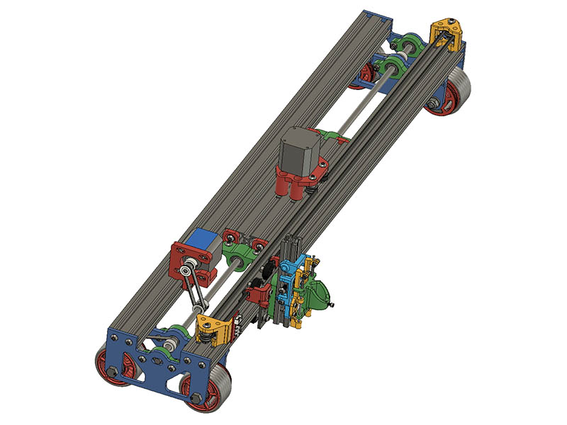
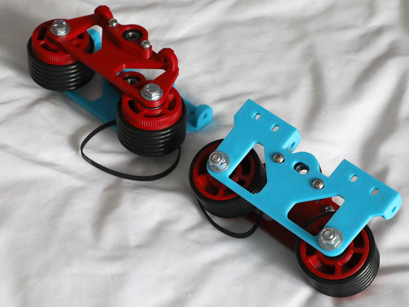
My biggest problem was being able to adjust the belt for the motor to M8 rod & also be able to adjust the belt between the M8 rod & wheels. Looks like this should work. I won’t have to reprint the wheels at least. I might have to adjust the offsets a little bit more. I am also going back to the O-ring wheels as those worked the best for me & since the wheels are supported on both sides now, I added as many as would fit (6 on each wheel). Here is what I have so far. The parts in green can slide 3mm each way & have skate bearing in each of them.
3 Likes
Think I have it adjusted for all the parts to fit. I had to order another closed loop timing belt. Shortest I have is 188 & it needed to be in 148-152mm range. 148 is what I calculated, but when I drew all the teeth in the belt, comes out closer to 152. I ordered 146, 148, 150 & 152mm lengths. One of those should fit. I had to change the wheel spacing from 110mm to 115mm for the wheel belt to fit. I changed the 2060 brackets to 2 parts on each side with a T-nut connecting to the 2040s underneath. Maybe I will have the new parts printed by the time the new belt comes in.

2 Likes
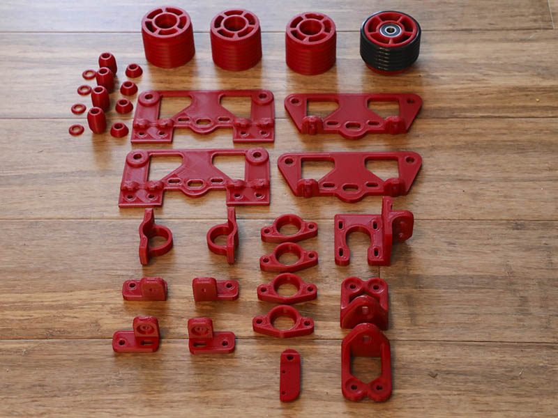
I finally have all the new parts printed & the hardware from China. Sometime soon, I should be able to put this new design together. The main thing I changed since the last assembly image shown was to cut out the outside bottom T-Nut connections on the 2 main plates. Looks like it should have enough support with the wheel bolt & the back plate that screws into the ends of the 2040. That should give me an extra 25mm width of travel which looks like 24" width with 800mm 2040s. I also changed the 2 top yellow idler pulley mounts to mount to the ends of the V-slots. I spent a few days last week tuning my printer to get more accurate prints & switched back to klipper firmware to mostly be able to use input shaper. That did make a difference. I am now mostly printing at 80mm/sec up from my 50-60mms. I see the latest version of Marlin is starting to use input shaping but will wait on that for a while. I did the manual input shaping & didn’t use the ADXL345 board. I am starting to think about playing with tire treads as an option replacement for the o-rings. I have done a coupld of those designs but looking for some other ideas. Anyone have some links to something like tire tread design?
1 Like
This is just a search: Search Thingiverse - Thingiverse
1 Like
Thanks. I had not done a tire tread search on thingiverse in a while. The ring_3.STL in that 1st link looks interesting to play around with.
No worries. I had because not too long ago I added micro swiss direct drive to my printer. So I have been looking at tpu for a while. It is a little pricey though, so holding back. Good Luck.
This is the 95A hardness TPU I use at $22.95 a roll. They run some discounts at different times of the year. Zyltech Filament - ZYLTECH Specialty Filament - Page 1 - ZYLtech Engineering, LLC
I do like the softer 85A hardness better from eSun, but is a little trickier to get started & also more expensive.
2 Likes
@geodave not sure if you’ve come across this already but this looks like a interesting option once you select a treat pattern.
Looks like they could have some good traction.
1 Like
Thanks for that link. I knew someone on here would have come across something interesting that I have missed. That is an interesting tutorial. I was just thinking the other day about how to do molds for these & low and behold someone gave me the link for it. I can get better prints from plastic than with TPU, so this might be a better choice. I did reverse engineer one of the tires on the previous link, but now need to resize it to fit my tire. I always find it better to redo it the same size as what I am using as a template before resizing for my needs. I will play with previous design first before going down this rabbit hole as I don’t want to be too scatter brained.
2 Likes
Hahaha, so simple, that is insane!
2 Likes
I am starting to assemble today. I am going to change wheel plates a little more to have bigger inner slot for bearing. It does not bind when tightened but seems like the slot should be a little bigger to keep it from possibly binding. I am connecting the back plate on the sides rather than using tapped hole which cuts down on the number of tapped holes. I did tap one of the 2040s on both sides to attach the idler mounts to the ends.
I also just noticed this interesting remix of my original rolling plotter that was done over a year ago also using one motor to drive both sets of wheels. He is driving both wheels on each side rather than just one wheel with some interesting linkage. https://www.thingiverse.com/thing:5147892 @dkj4linux might want to look at this one as he has a laser attached to it with a proper z-axis.
3 Likes
Can you bring it to RMRRF? https://rockymountainreprapfestival.com/

3 Likes
That is probably too far a drive for me from Western NC & I am not interested in flying there. I will keep that in mind if something changes between now and then. Thanks for the info.
2 Likes
Ship it out to him 
You know have you looked for hobby shops rc truck tires?
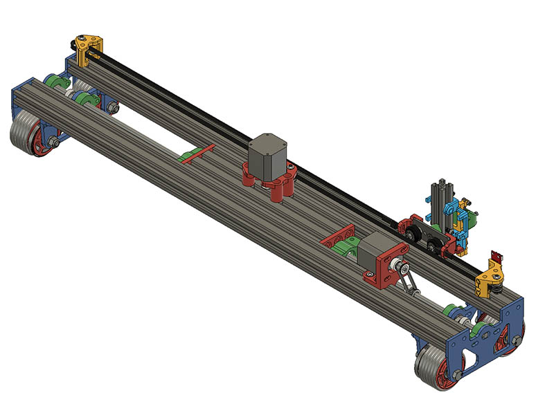
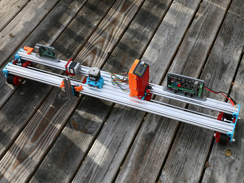
I got this new version mostly assembled yesterday. Since I had to get a 1-meter long M8 smooth rod, I decided to go ahead and make the plotter 1-meter in width. The 1-meter rod is a little shy of 1-meter, so am making some 7mm width spacers to add between the back plate & outside bearing plates. That seemed to be the simplest way to do it. I thought getting that long m8 rod would be a problem getting lined up properly, but using a simple 3d printed shim 26mm wide while tightening each bearing position made it quite easy. I did have a little bit of forethought & put the wheel locknuts to the outside to make it easier to change the O-ring tires to TPU or replace the O-rings down the road. I also changing the F625 bearings to these bearings. https://www.aliexpress.us/item/2251832664674464.html They seem to be a better quality than the original ones I was using.
4 Likes