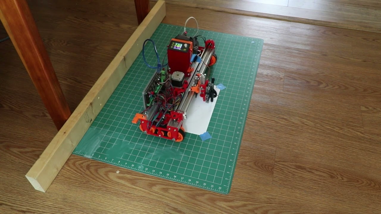
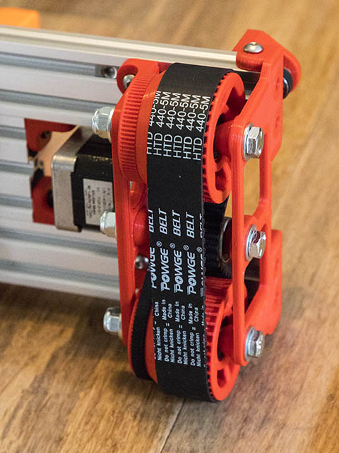
I wonder how well these polymer bearings would hold up? I have 4 of these & they feel pretty good with the M8 rod. I am also not sure how well these would fit into this design. Maybe I will just get some 5/16"x2.5" bolts from local hardware store to test this current configuration. I already printing a main plate yesterday anyway.
Amazon.com: 3D Printer Solid Polymer LM8UU Bearing 8mm shaft - Igus Drylin RJ4JP-01-08 for Anet A8 Prusa i3 3D Printer RepRap : Industrial & Scientific
Someone on the openbuilds forum suggested 3d printing a shaft, but not sure that would hold up in long term.
Thise should work. I have some of those on a printer of mine and they rotate axially with no disernable resistance.
I’ve been out of the game for too long now but do still use my “rolling gantry” machine from a couple of years ago. It initially was intended to free run on the floor/worksurface but “drift” was a problem that I/we could never overcome. Eventually, I simply converted from closed-loop belts to a more traditional LR “anchored belt” approach and haven’t looked back.
I know it’s great fun to engage some of the brains on this forum in a joint exercise… brainstorming along toward a desired end. And I’ve enjoyed following along with this discussion, lurking and with nothing to add. But with this latest turn in the discussion to wheels and bearings, I’m inclined to ask (because I don’t know…) what are the advantages, if any, of a printed wheel design and “tracks” vs. LR-style roller-blade wheels? I’m assuming that on rough surfaces like concrete the tracks might smooth out the “ride” more than wheels that are more susceptible to minor dips and bumps? Would one track better than the other in this application? If wheels would work, it’s pretty hard to beat the proven setup of the roller-blade’s dual 608 bearings and a spacer… 
Just wondering… and enjoying the discussion. What fun!
– David
It just seemed like I was getting a lot better accuracy than a couple of years ago and wanted to see how much better it could work. With @jamiek idea of giving the wheels support on both ends, seems like I might get a lot closer to very good accuracy. An untethered machine could have a lot of interesting possibilities if the accuracy is there. I actually started working on this again this year because my next-door neighbor was wondering if I could engrave with a router of laser a large red oak slice for a gravestone. My sphinx CNC machine only goes up to 12" square work area & I do not have a big enough space (20x12 shed) to use a LR. I did have an early version of the MPCNC with about 20x30" work area, but it took too much room in my limited shed. Since I didn’t have something that would work for this size, I decided to pull the rolling plotter idea back out & see if that could possibly fill the bill. I was figuring if I only did outlines & didn’t repeat a pattern, any inaccuracies would not show up. Anyway, that is the back story behind this current build.
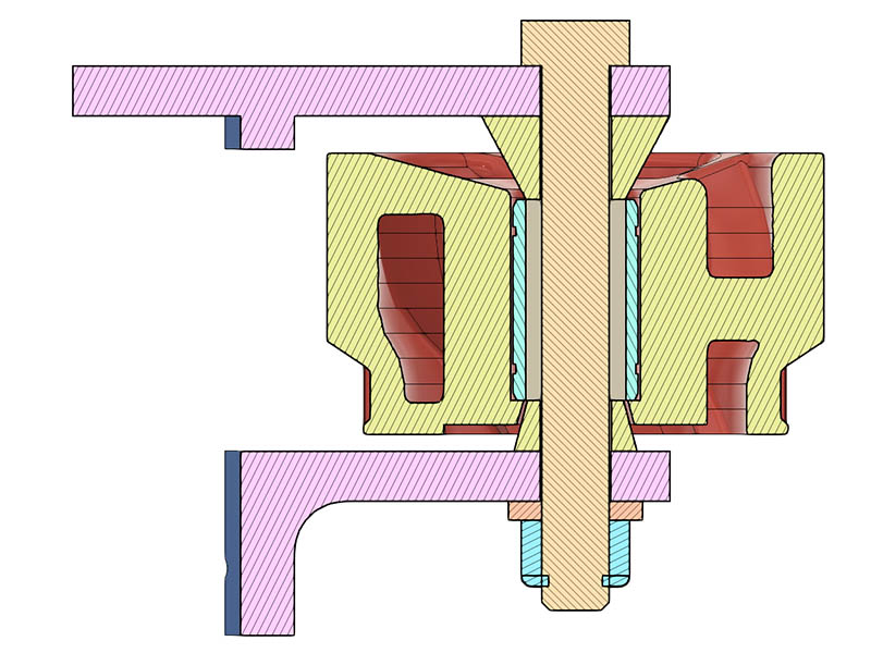
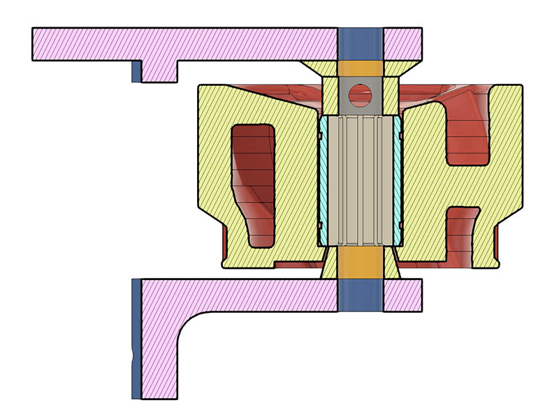
As to those Igus Drylin RJ4JP-01-08, I do not see how to get these to be confined in the wheel since I do not have a way to constrain them at one end of the wheel. It did not seem like it would work but did draw it up to be able to see the problem better. I used a M8 bolt in this drawing, but would use the M8 smooth rod if it worked. Looks like it will wobble out the top with this setup. Anyone have suggestions for that? Could probably use this on the top end of the M8 rod to hold that side in place. Lock Collar - OpenBuilds Part StoreI think the next step is to print the other parts needed for one side of the plotter & see how the bolts work.
That lock bearing looks like it would work with the igus bearing. Think I will still try the bolts first since I would have to reprint the wheels to test that bearing.
It will work, but it is a tight fit. This is a good thing! the 8mm rod should fit, but it might take a little persuasion. Make the smooth rods the correct length first, then put them in the freezer for an hour or so. They ought to slip into the bearing while still cold. A little oil on the surface will help, and the 608 bearing being warm will also help. Make sure you get it where you want it, it could be tricky to remove the smooth rod later.
I was able to get 608 bearings over 8mm smooth rod with just a drop of oil, the tolerances are really close, but it will fit.
I have no problem at all understanding why you are enjoying this project, Dave… and please know I’m not questioning any design choices you make. I know the tremendous value and satisfaction that comes from taking on a challenging project and interacting with folks of similar ilk. That’s what makes it so much fun. I miss, in many ways, all the brainstorming and collaboration when working in industry on massive defense projects… but with all the tools we have today and the sharp folks in this forum, this is way better. Build fast, test/fail fast, adjust/fix, and build again… rapid iteration seems to be the recipe. Works for SpaceX… and, with a 3d-printer and the desire to try stuff, I think it works for us as well.

– David
Thanks for suggestions. I am getting better at not going thru as many iterations of design but seems like I still find something I wish I had of changed before printing the current part. I am currently going thru about a roll of filament once a month.
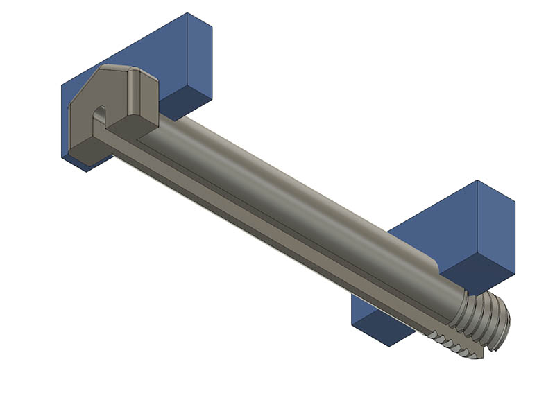
One thing I have experimented with a couple times but not integrated into a full project is 3D printed roll pins for 608 breaings. Just an oversize tube with a slice missing so it’s an extruded C shape. Experiment with wall thickness and the oversize OD until you get something you like. (The size of the gap is calculated from the initial and final OD plus clearance).
If you dont trust friction to hold it in place you can put “fins” on one end to act like a bolt head without changing stiffness, and the other end you can put radial holes for a cotter pin or something.
There is a chance that imperfections in the print could skew the bearing slightly, but I think that effect should be really, really small, and since it is sprung, it has zero play.
I thought about trying plastic roll pins in place of 5/16" bolts for the MPCNC but they are hell to disassemble, and I wasn’t sure if creep would loosen them, or how much. For low loads, they might work better.
I had not thought of putting a slot in the bolt line a rolled pin. I would probably thread the other end to put an M8 nut or 3d printed nut on. It is really quick print & might hold up for light loads on this. I will try the real bolts first. Here is a drawing I came up with from your description.
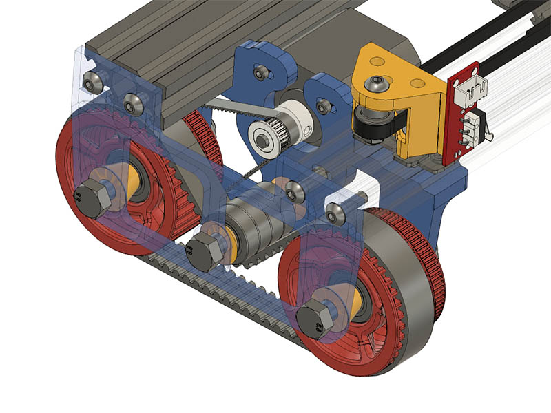
I have some M5x60mm screws coming in the mail today from openbuilds & got my 2 - 2040x800mm V Grooves from Zyltech yesterday. Zyltech has more options for lengths, so no cutting involved. I started thinking about the idler pulley for the HTD5 belt that is currently using the M5x60mm screws. I wanted to use the same 608-2RS bearings for this but didn’t have enough room for a housing for the bearings. I then realized why do I need a housing for them. The belt is constrained with the wheels & shouldn’t really need it. If I did, could always add some sort of fender washer. This would also make it easier to source the hardware as 5/16" is a good substitute for M8, but I don’t see a good substitute for M5. It is also easier to find longer M8 than M5 hardware. If I end up going to 25mm wide belts, those bolt lengths would probably go to 70mm. I bolted a few of these bearings tight together with a M8 bolt and they move well. I will probably end up ordering some 25mm width HTD5 belt soon but will see how well the 15mm wide belt works first. It seems more difficult to find 30mm width HTD5 belt. Here is what I had in mind for those 608-2RS bearings & it does look like it fits without hitting the inner drive belt with lots of room to spare.
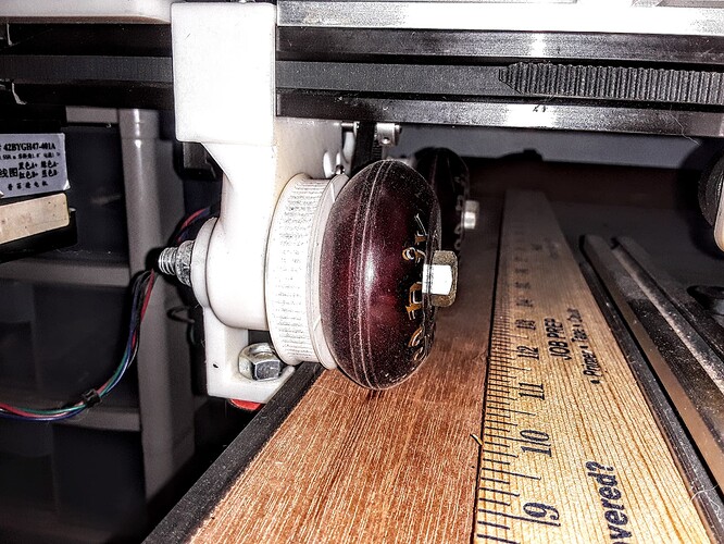
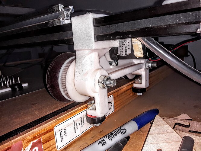
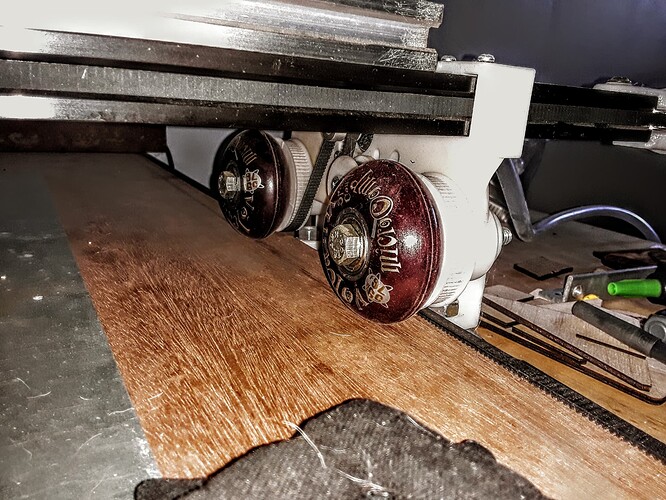
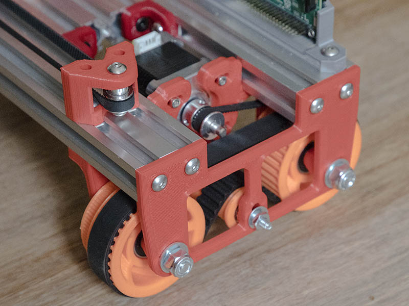
My M5 hardware will not be here until later today, so I went to ACE hardware to get some 3/16"x2.5" screws since they are not too far off M5 (4.76mm) & they ended up being #10 which is the same as 3/16". I was initially thinking #12 were the same as 3/16" & figured since this is on the idler & the belt is pulling up, a smaller diameter probably doesn’t matter for this use. Of course, #10 is the same as 3/16", so it didn’t make much difference with the M5. In putting it together, I needed to rotate the 20T drive pulley around in the motor. I had it rotated with grub screws to the outside before. When I reprint the tires for 25mm wide belt, I will move that tread another 2mm out to make sure it clears ok. The motor wheel plate I printed 6mm thick & the outside plate 4mm thick. I was thinking I could go a little less than that but seems like motor plate needs to be 6mm thick. It was initially a little tricky getting that tire belt on there but putting free wheel on last makes it a lot easier. I have to reprint the idler pulley with limit switch on it where it connects on top of V-Slot before I can test this. Those wheels do not flex at all thanks to Jamie for that idea. Here is photo of it together.
That is looking proper!
Definitely rolls better, but accuracy is still not where I wanted it. I ordered some 25mm wide belt today after redesigning the parts to fit the wider belt. That will take 2 weeks to get here, so might try playing with some other settings in the meanwhile. Tighter fit on the wheel bearings might help some more.
[Edit] Just realized I have the HTD5 tire belt tensioned from the bottom instead of from the top. I was wondering why it was close to the motor pulley. Just got my M5 hardware, so will swap it around when changing that.
Heal and toe measurements are good? If it is angled out at all it would lose some accuracy.
I had not thought to measure that. From my measurement, seems to be correct. It could be off 0.1mm, but visually with metric tape measure looks good to me. I am going to reprint the wheels with tighter bearing clearance & a few other adjustments & see if that helps any. I have not changed them in a while. That belt was a pain to get in there the other way around, but that is best way to do it since I have no clearance problem with motor pulley that way. When I switch to the M8 bearing idlers it will probably be easier.
I decided to weigh it this morning and see how well balanced the weight is since I moved the carriage motor closer to center. I don’t know that I weighed it since that change. The machine currently weighs 9lbs 7.2oz.
I put the near side wheels on the scale with the far side about an 1" below the top of the scale. With the carriage closest to origin, that origin side weighed 4lb. 10.6oz. Weighing that same side with carriage furtherest away, it weighed 4lb. 6.4oz
With the carriage closest to origin, that origin side weighed 4lb. 12oz. Weighing far side again with carriage closest to that side, it weighed 5lbs even.
If I am looking at the right, that is a weight difference between 1.4oz & 9.6oz. between the 2 sides.
I have my other C-Beam & the 800mm lengths of 2040, so new options to try now. Both of those options will give it some more weight which might help give it more grip. I am still thinking better grip is the problem but could be something I am not seeing yet. I might even try the laser on there this week with the C-Beam. I might have to make a new carriage assembly, but maybe not.
I printed a new wheel last night & seems like my printer is not printing as well as it was. I have the parts to fix & upgrade my zyltech Gear printer to direct drive, so maybe I can get better prints on that.
I received the 25mm wide HTD5 belts the other day & am starting to put this modification together. I have a couple of more spacers to print for the other side. I had to take 2mm off the thickness of the corner clamps for the 2060 in the center as the motors looked like they would hit them. Might have worked but was an easy change & used M5x10mm screws instead of M5x12mm. The first side was a bit of trouble getting it on there but seem to have found the best order of assembly, so other side should be easier. I got the C-Beam order from openbuilds, but some of the center holes were around 1.25mm off which seems a bit much for tolerances on this. I sent them a photo of it & they sent me another one. The 2nd one had the same problem, but at least all the holes I needed tapped were already done. With this new problem, I decided to make those end holes slots & did a couple of test prints to make sure they would work. I also thought that maybe this design is telling me to approach the connections differently, so I made these so I could use 4 T-nuts on the end plates instead of the tapped holes.
While taking the other side apart, I discovered I had put one of the bearing spacers on backwards. That certainly could have caused some inaccuracy. I will double check this on the assembly this time.
Here are a couple of photos of the one side.
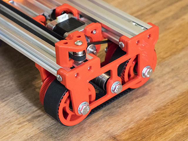
Seemed like this rolled a little better but was still a little off. There was only 1oz difference in weight between either side, so don’t think I can really compensate weight difference since gantry moving back & forth would change the weight by more than that. I did not bother putting the pen on there to test it.
I am going to try swapping the C-Beam for the 2040 before testing it again. This gives it 3.5lbs more weight & more room to put ballast if I need it. I am using this plate for the C-Beam Gantry. V-Slot Gantry Plate - Universal - OpenBuilds Part Store I drilled a 1/8" (3.175mm) hole at the top on each side where I add the belt clamp parts. That change, a longer V-Slot 2020 & adding a longer 3d printed shim plate was all I needed to use this. I do loose a little more width since this plate is a wider. Think it is about 10.5", but I might could adjust the design a little to get a little more width if this works. The wheels hit the bottom inside plate where the T-nuts are connected underneath. I could use drop-in T-nuts there to gain a little space which would allow me to shorten part underneath.
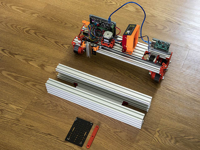
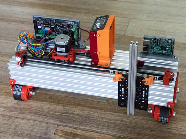
Time for some spiky snow tires?
It is the middle of summer here, but spikey wheels would eliminate the HTD5 belt.
