Rolling pen plotter to vinyl cutter

I know that when the motors are moving they will make a sound. Particularly when moving in multiple directions it could almost be described as “musical”.

what I was experiencing was after movement was done, there was a slow decreasing whining sound. Almost like it was trying to move, but couldn’t.

After adjusting the current this sound when away.

Yeah, that’s what the quote below means… The sound after motion is done is the holding torque. It often hisses. It doesn’t “Sing” because the stepper coils aren’t being cycled as the motor moves.

Hmmmm, Back to the servo control topic
I’ve connected the servo to the zmin pins. I think that is what the mods to the pin file did - unless I’m wrong.

When I send a M280 P0 S90 or S0 or S180 nothing happens…
If I try P1 or P2, it says servo out of range.

Man, I was really hoping this was it and I could move on with the project.
I did see that Ryan has a fluidnc board for pen/laser but I really don’t want to spend $45 on it this as it was meant to be an inexpensive project since I had the boards already.

What am i missing to get the servo to work on Marlin?

I would start troubleshooting by checking out the pin. Carefully (with the board unpowered) hook up a voltmeter to your proposed PWM pin. Use an M42 to set the pin PWM directly. Use S values of 128, 192, and 255. You should get values of around 2.5V, 3.75V, and 5V for the three values.

If the voltage stays around 0V, then you either have the wrong pin, or the pin is burned out. If you only get 0V and 5V from the pin, then the pin is either not a PWM pin, or it is not acting like a PWM pin. It is possible to use a timer that drives PWM pins, plus, based on reading the Marlin source, some pins appear to be protected. If this is the case, I suggest you use one of the PWM pins I identified on Extension-2 above.

So I’ve only used my voltmeter 1 time before this and that was on this same project. So please bear with me.

is this correct setting on the volt meter?

And are these the pins to set the probes to? red and black lines?

That looks right for the meter settings.

Those pins should only ever show 5V when the board is powered on. Those are not PWM pins, or even switchable, they are meant to provide 5V constant power. The “S” pin for the servo port is the one to test. Put the red lead there.

You can use the black line one as the ground reference though. Personally, I would use the power supply ground though. It’s more reliable, and also safer. Less chance of a short circuit.

I…am such…an…idiot.
First, I did know better that it was the signal wire pin that I needed to test. I just had + - in my head and called those out instead.

Second. The Z min is the correct pins to use. I originally had the servo on the Z max and when I swapped it I didn’t see that the set of pins (is this called a header?) was rotated 180 degrees, basically swapping the + and s pins

I ran the M280 P0 P90 and P0 commands and it works!

Unfortunately it is reversed in the direction I want it to go.
Is there a way to reverse it? my carriage is set up for the servo to move in the opposite direction, which it did when using grbl.

although I am working on a new carriage design so it might not be needed. The one I have has too much play in it and I think is what is causing my line to wander.

3 Likes

Unfortunately it is reversed in the direction I want it to go.

If the movement is on the correct side of the servo, then the direction does not matter. The fact that 0 may be up and 125 might be down does not make any difference to the g-code. If the movement is on the wrong side of the servo, then, sometimes, you can just reverse the horn. Unfortunately, almost all servos have a limited range of motion.

Yeah, and thinking about it more, I just need to make 0 the up position and 90 the down
It should work how it is.

Thanks

Ok, update
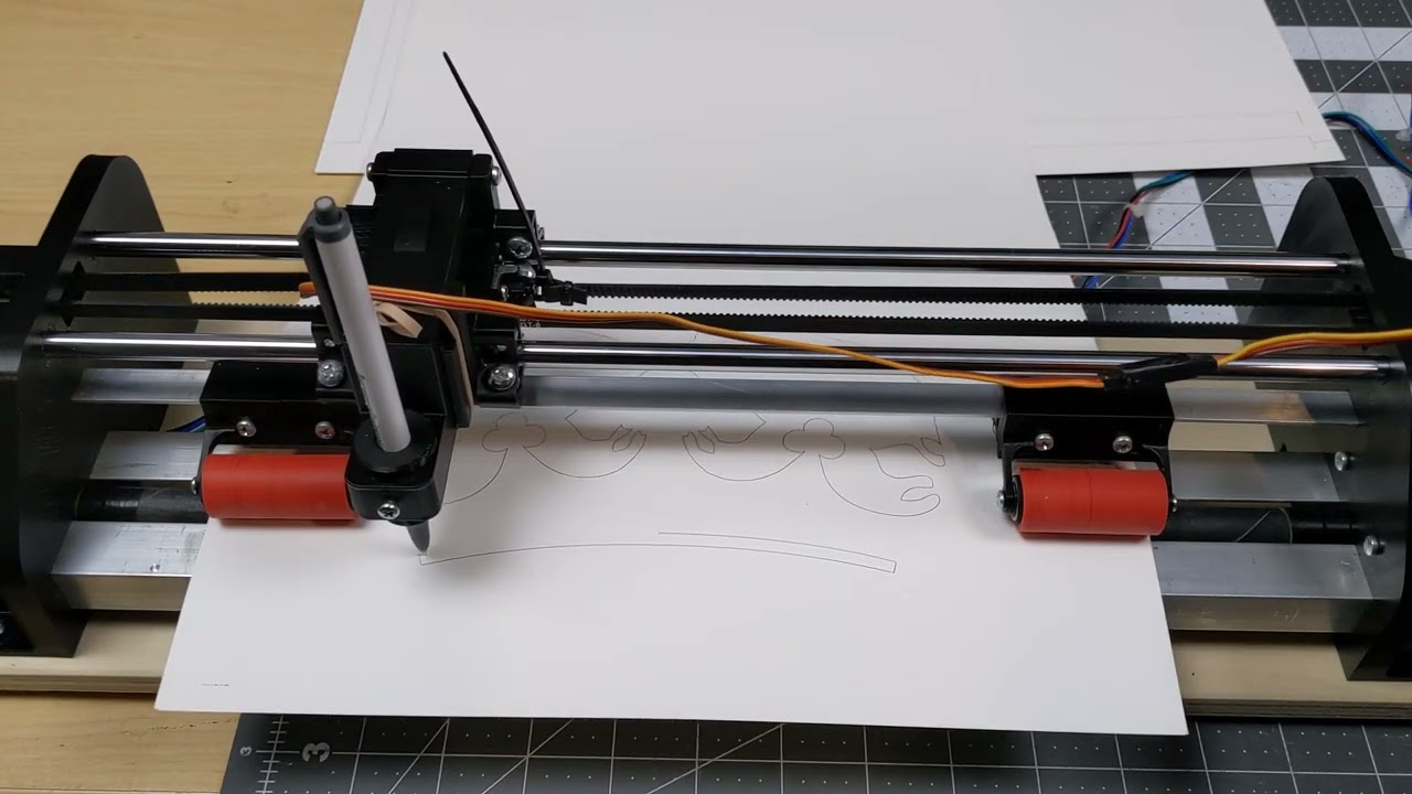
I gave up on Marlin and switched over to a board that can run fluidnc.
I had a side thread on getting it to work here if you are interestd.

and now its working!
there is an unexpected pause at 00:43 which I need look into and figure out.

Next steps.

  • wire management for the servo wire.
  • mounting the board
  • get the vinyl cutter in
  • work on speeds - the video above is kinda slow.
3 Likes
YES!!! Congrats.

Thanks to you and everyone who helped out.
This was a huge learning experience for me. In design, build (the easy parts in my mind) and all the firmware stuff.

Looking forward to wrapping it up though.

1 Like

one quick question
After I run a gcode I am not able to enter any other commands. Instead I get a 404 page not found message.


Why is this?

Either that Z0 command messed something up (it is not a complete command should start with a G0 or G1), or you are no longer connected to the device.

Entering G0 worked. I was able to do other commands and re-run the program

I have successfully committed vinyl cutting

now I want to optimize the workflow from design to cutting.

1 Like

Wow and it looks good to! I did vinyl with the mpcnc, but it was a lil effort to changeover and i have a little variance in my board, so i always wanted a machine like yours!

Thanks! I’m pleased with it also. Although the corners aren’t nice and crisp like I’ve seen on “professional” cutters. Though I wonder how crisp they are on something like a cricut machine. I may need to look into tool path settings. Right now I’m using a 2d trace tool path in fusion.

I wonder if the angle of the knife makes a difference here. I can’t recall what angle they are that Ryan has on the v1 site.


That is one of the drag knife blades Ryan sells. I think the corners really depend on how far off center the point of the knife is. It has to be some off center in order to function as a knife. That offset is what orients the knife as it is dragged. A smaller offset and less runout of the blade will produce sharper corners.

This one is maybe .5 - .6mm, pretty small. The corners are imperfect if you look really close. (Really close.) To avoid that, a tiny radius on the corners will hide imperfections. A slightly bigger issue is that the start and stop points on a line need to overlap by about 1mm in order to ensure that all shapes are completely cut out.

There were some tips for using Estlcam to have a “lead in” for shapes to ensure a complete cut out somewhere in the docs, but I can’t find it now. Well, I remember how anyway… I’m also not too averse to a bit of X-acto trimming while weeding the vinyl cut-out shapes, as long as it isn’t much.

good to know.
I suppose if I really want sharp corners I could break the shape apart into separate lines (at the corner) vs a continuous line. Would increase cut time, but what I’m using it for would be short cut times to begin with.

1 Like