I’m wanting to build an “infinite” rolling pen plotter but convert it to a vinyl cutter.
I found three variations of this that I am reviewing and planning to take what I perceive to be the best parts of each and build my own.
the area I am needing help with is the control boards and firmware.
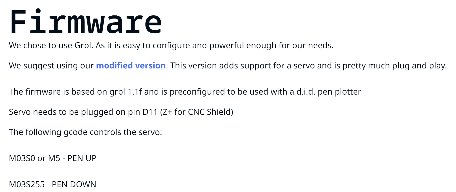
All of these use a servo to lift the pen up and a modified grbl firmware that converts z movement to pwm for the servo.
all of these also use an arduino with cnc shield. however I have an unused rambo mini.
is it possible to flash the rambo mini with grbl and attach a servo wire?
I do have this which I bought a few years ago and never used but should work fine but recently have been learning it is not that reliable.
Any other recomended options for arduino cnc shields?
I don’t have an answer to your specific question. I know there is a version of GRBL that runs on the full Rambo board, but I’m unsure if this version of GRBL will it will run on the Mini.
As an alternative, you can put Marlin on the mini-Rambo. Using Marlin, you can control available pins using g-code plus Marlin has g-code specifically for use with servos. V1 maintains versions of Marlin for the Mini Rambo, but you will likely need to make a few for your specific hardware setup.
The question is what tools will you use to generate the g-code? How will you map Z movement commands to Servo lift commands? These lifts could easily be post-processed in, but a script would need to be written (if one doesn’t already exist). Post-processing them in means any CAM solution that handles the specific firmware could be used to generate the g-code.
I’m not sure of your exact use case, but if you don’t need ‘infinite’ but just really long, then the Lowrider could do the job, though it is probably more expensive than the DIY projects you are referencing for your build.
I’d love to see a picture of this machine when you have it up and running.
Marlin has M280 and M281 g-codes for controlling servos.
You will have to enable servos and recompile the firmware. I’m guessing, since your plotter/cutter will not be set up the same way as your Lowrider was, you will need to recompile the firmware for more reasons than just servos. I don’t know all the in/outs of Marlin servos, but I’m guessing that you first have to enable servo support by uncommenting the following line in configuration.h and setting the number of servos to 1:
//#define NUM_SERVOS 3
Then you will need to add the following line to pins_MINIRAMBO.h:
#define SERVO0_PIN [some number]
The “[some number]” is the pin number of an available PWM pin. Note there are not many available PWM pins on the Mini Rambo. The best choice is also used by the display, so if you want to use a display, then you will have to jump through some additional hoops. If you are not going to use a display, you are golden.
If you have a cheap 9G servo, you can set up servos and test sending g-code movement with what you have now. No need to wait until you have your machine further along.
As for GRBL, things get a little more complicated. There are a number of implementations of GRBL, each targeting a set of control boards. It is unlikely the versions you reference above will run on a Mini Rambo. It is likely that these versions will only run on the CNC shield.
If you are going to be using Fusion360, then you could set things up as Laser M106/M107 commands. You would then have to search and replace all the M106 commands with the Servo down command., and the M107 commands with the Servo up commands. It is a bit hacky. It is also possible for someone to edit the Marlin postprocessor to automatically insert the Servo commands in place of the laser commands. If you go down the Marlin road, let me know, and I’ll see if I can figure out how to modify the postprocessor to make the conversion.
I used the big brother to that for 2 years, til I blew it up with manual movement, works fine, just not as finessed as other boards. There is a reason it is still being sold, cheap and reliable.
Now, for the pwm, I am not sure it can accommodate it. You may find that it can.
For the rambo, it may work, but not sure. Did you google rambo and grbl?
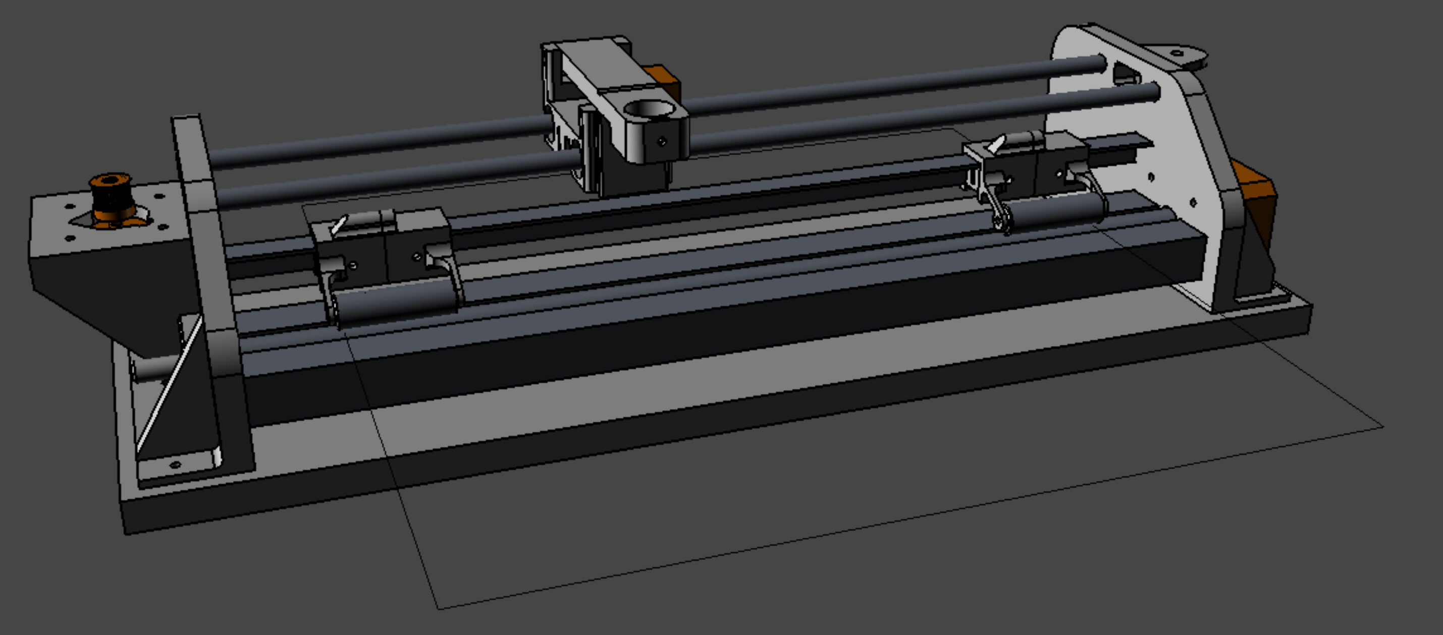
Update on the pen plotter/vinyl cutter.
I have the CAD finished and have started printing parts.
it is heavily based on the d.i.d. scalable pen plotter I showed above.
none of the plotters above are very wide.
I am making this one be able to do up to 12" wide vinyl which seems to be a common size for the larger cricut machines.
for firmware and control board, I am going to keep with the arduino with GRBL. there are a few firmware varieties out there already that are set up for pen plotters and I figure that will be easier at this time.
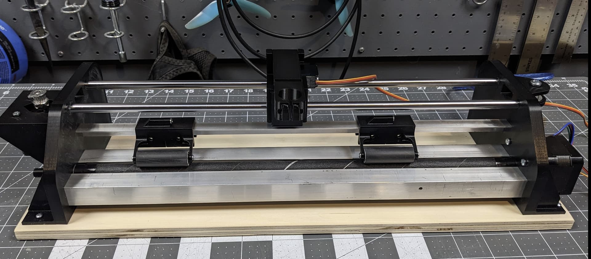
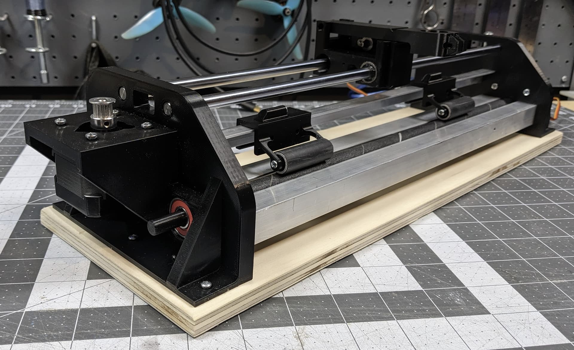
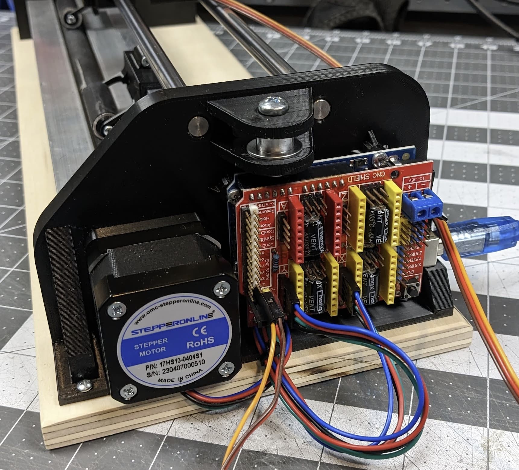
(still need to add the stepper driver in that last image.
Before I connect the belt, I want to test the motors and servo directions.
Question on the cnc shield.
I have seen some set ups that use the micro step jumpers and some that don’t and can’t find a resource that explains when and when not to use the them.
Do I need to use the micro step jumpers?
one reference I found said that I would need to make adjustments to code in Arduino?
Just a little confused/lost on that topic. Any help would be appreciated.
Well, that depends on what resolution you want to get from the motors.
Most polulo style drivers, like the A4988.and the DRV8825 go to 1 full step per pulse with the jumper blocks open.
So with a 16T pulley, that is 32 mm / revolution, and 200 steps / revolution. This means that every step is 0.16mm of belt travel.
With the A4988, all three jumpers in place gives 16× microstepping, so that means every pulse (minimum controllable.distance moved) is 0.01mm.
With the DRV8825, all 3 jumpers means 32× microstepping, so each pulse is 0.005mm.
Microstepping also makes the motors less noisy. One of the reasons the TMC2209 drivers are so quiet is that even though we set them to 16× for control, they internally use 256× microstepping.
I have some simple projects that use stepper drivers directly from an Arduino, and they do not have the jumpers in place at all. It works, so you do not need those jumpers, but they are nice to have, and the noise abatement alone is worth it.
this is exactly what I was looking for. Thank you! I could not find a clear answer like this anywhere.
noise abetment would be nice since this will be used indoors so I’ll probably use all three jumpers.
One comment on another forum mentioned needing to add specific code in Arduino, I’m assuming that is not needed?
Is there anything else I need to take into consideration if using all three jumpers?
I didn’t do anything specific for my arduino sketch, but I was basing everything on full steps anyway. (It’s for moving a focus mechanism, it gets used only occasionally, and not for long.)
I think the “specific code” is probably just adjusting the steps / mm, but that’s more a configuration chamge than a code change.
To the best of my knowledge, just that it will take 16 (or 32) times as many step pulses to move the stepper motor the same distance.
Does anyone have a recommendation for a grbl gcode sender that works with the arduino/cnc shield setup?
I’ve been trying to use the Universal Gcode Sender program, but am having issues with it. I can get it to run on my old, very slow and annoying computer, but not on my primary computer. I use G90 to move and it will, but give it the same command and either move way to much, not all or or in a few cases move in the opposite direction.
what about cncjs? I’ve heard of that before, but windows defender pops up warning it could cause harm. anyone use it? is it legit?
My windows 10 PC works fine.
On my Windows 11, the first time I tried opening it I got o a message that not all modules were loaded. Since then the splash screen shows it loading then closes and nothing happens.
I’ve found comments about disabling antivirus, removing a directory from the c:users folder (I don’t even see the directory mentioned), and uninstalling java. nothing works.
Just got a reply from the google groups for UGS. They pointed me to another folder to delete a directory related to UGS to try. I’ll try that when I get home.
I’m still interested in cncjs. Did some looking and found a few people who really like it.
I’m assuming it is OK and the windows defender warning I’m getting is just cautionary.
So I got UGS to work and tried out cncjs. I’m liking cncjs but I think it simply looks nicer. Not much of a reason though.
However, I’m getting frustrated with calibration.
I use the g90 code to move the pen, measure it, calculate the needed change, and change it. Seems to work. Ok…
Then I enter another movement in the same direction and it won’t move. Then try to reverse it, -movement, and it goes waaayyy farther than it should.
Am I doing something wrong?
Tonight I will run some movements and show you what it is doing.
I think I may have found the answer to one of my issues - the difference between G90 and G91.
I’ve been using G90. Correct me if I’m wrong, but that is Absolute, meaning if I move G90 x5, then try that same code again, it is already at 5 so it won’t move again. Where as if I use G91 x5 repeatedly, then it will continue to move in increments of 5.
I’ll try that tonight too and see if there is any difference.