Rolling pen plotter to vinyl cutter

@vicious1 I am looking into how to edit marlin now. I have never done that yet so any hints would be great. @robertbu suggested a few things a number of posts back (Rolling pen plotter to vinyl cutter - #4 by robertbu) that I am now reviewing. He suggested that I will need to use some of the pins used for the screen and I need to learn how to set those for the servo.

I’m guessing I should use the standard marlin firmware vs any V1 firmware right?
I need to figure out how to adjust the microsteps. on the arduino cnc shield I could do that with the $101 command. is that the same for Marlin or different. I saw reference to needing to do that in the .h file.

if I understand right I can flash marlin using the arduino IDE? or something else?

again I am completely new to this so lots of learning going on here.

I think a V1 firmware might be a good start. MPCNC, no dual if we still have one. From there XY should be close. You will just need to get teh servo hooked up.

I am in and out today, a lot of house stuff happening (deep after xmas cleaning).

I can check back later.

WElll, I would say no you need to use PLatfarom.io. Arduino might finally work but I have not tried in years.

The Arduino IDE works fine on Linux. On Windows it runs into command line length issues and cannot compile – Or at least it did the last time I tried ot on Windows. (I usually use PlatformIO even on Linux, but recently compiled non-V1 Marlin on the Linux version of the IDE.)

@vicious1 @SupraGuy thanks. so far using PIO seems pretty straight forward.

Per @robertbu I uncommented //#define NUM_SERVOS 3 and added the line #define SERVO0_PIN [some number]
I just don’t know what the pin number that I need to use is. I’ve looked for diagrams of pin numbers but either I am not finding one, or I am not looking for the right thing.

I’m fine not using the LCD if that is the easiest way to do it. Having the LCD would be pretty nice, but not if it is pain in the butt to get there.

three other things I’m wondering about
1 - If I use the pins from the LCD, should I disable (comment out) any LCD functions?
2 - how to adjust steps/mm (I mistakenly called this micro steps in the previous post)
3 - do I need to adjust the driver current for the steppers I’m using? they are different than what you supply Ryan.
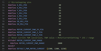
I did notice this in the pin_MINIRAMBO.h file.

thanks again for all the help guys.

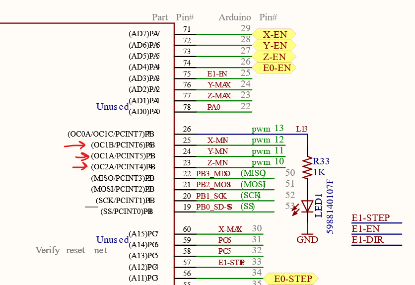
If you are using a display, I’m not aware of any free PWM pins on the Mini Rambo. If you are not using a display, then, based on the schematic, there are three available PWM pins, which I’ve labeled in red in the following image.

Looking at a pinout diagram for the Mini Rambo, P1 is labeled as Exp 1.

You can verify the pins by carefully hooking up a voltmeter to them and using an M42 to set the pin state. A ‘S128’ parameter should give you around 2.5V on the pin.

Some of the end stop pins are PWM capable (XYZ min). That gets you power ground and PWM in one spot.

If you need all three endstops use one of the MAX as a min, or home to max.

1 Like

I’m not planning to use any endstops so this is looking like a nice option as it allows for use of the screen.

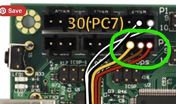
in doing to web searching on servos for rambo mini I ran across this bed leveling device that uses wiring similar to servos (or seeming to anyway). Scroll down to the mini-rambo wiring, second image.

it claims to use #define SERVO0_PIN 30 for the servo.
I’m assuming I can just use the wiring in the green circle

Thoughts?

That does not sound right.


Use 23, 24, 0r 25 for the pwm. Might be defined as PB5,6,or 7

Interesting…
I just found this on the minirambo wiki


I believe the example shown here is to use the x-min for the pwm servo?

https://reprap.org/wiki/MiniRambo

there is a link for an example mod to the firmware.
I think this is similar to above but modifying the z-min/max for the servo instead of x-max/min

.
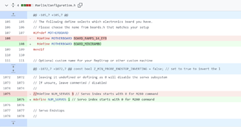
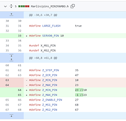
screenshots from the servo example link


The way I read the above screenshot is changing the board type from ramps to MINIRAMBO (if I’m using a V1e firmware, this should be done. I’ll check in a bit EDIT - confirmed. it is)
Uncommenting the number of servos line and changing it to 1 (which I’ve already done)


I read this last screenshot as…
Line 33 is setting the servo pin to 10
Line 63 removes pin 10 from z-min (as it is now servo per line 33)
line 64 and 65 swap the z-min/max pins to free up the z-min for use by the servo?

either way, if I make these changes to the V1e firmware, I should be able to use the z-min for the servo?

That looks right to me.

1 Like

OK, so the first hurdle is solved I think.

I’m looking into the following

  1. Do I need to adjust for the motor current?
    for the Arduino cnc shield I needed to to this. it ended up being much lower than expected at 0.3.
    I found this line of code in configuration_adv.h and reference on the web as this being where to adjust the current…
#define PWM_MOTOR_CURRENT { 850, 850, 850 } // { 1300, 1300, 1250 }          // Values in milliamps

…However I have not found anywhere how to determine what the setting should be per a particular stepper motor’s specs. Mostly what I found was trial and error sort of thing and checking to make sure the temp does not go above 50c

  1. Adjusting steps/mm
    My X axis should be OK since I’m using the same pulley - I think… I might need to check that.
    However my Y axis is a roller so I can’t assume it will be the same.
    So I will most likely need to change that.
    Is this the code from, Configuration.h, that I need to modify to change it?
/**
 * Default Axis Steps Per Unit (linear=steps/mm, rotational=steps/°)
 * Override with M92
 *                                      X, Y, Z [, I [, J [, K...]]], E0 [, E1[, E2...]]
 */
#define DEFAULT_AXIS_STEPS_PER_UNIT { 100, 100, 400, 837 } // { 80, 80, 400, 500 }
  1. Post processing - I need to find a way for the post processor to input M280/M281/M282 for the servo up/down position.
    @robertbu , Previously you offered to help modify a PP for this. If you are still willing I would be grateful. I’ll be using Fusion360 and flyfisher’s PP.

Yup for the most part that is the only way.

Yes.

This one I have no idea about. I kinda assume there must be a trick to this with servos. No PP needed just a step per mm type adjustment. Someone here has to have done this before.

1 Like

I found some reference online stating that you can set the motor current via gdode so that you don’t need to re-compile for every change.

I found this under the Marlin docs site.

I’m assuming this is not a permanent change, but good to use to find the correct setting then make the final change in the firmware, recompile and re-upload right?

1 Like

That should work, I believe there is also a menu on the LCD to do the same. You have to also Use M500 to save or there is a save command on the LCD.

Sorry it has been so long since I used a mini, none of the nuances are fresh in my mind. For whatever reason, that setting was different between the mini and the full sized. I do not remember which was which.

Awesome! Thanks again. If nothing else I will simply reflash the board with an updated firmware.

When you change the firmware, at the first boot, it doesn’t know you changed those default settings. So you still need to load them.

M503 will print most of the settings you have.
M502 will delete anything you changed via gcode and load the ones from the firnware.
M500 will save anything you have loaded so it is available after a reboot.

If you send M906 with no arguments, it should print what values it is currently using.

1 Like

So I’m still having a hard time understanding how a z movement translates to the servo moving up/down to lift or drop the pen.
Everything I’ve read says a M280 code needs to be sent to move the servo, but any gcode for z movement will be Zxx or Z-xx. So wouldn’t a change to a PP be needed to send M280 any time the z moved up or down?
There is also M281 which tells what angel the servo to be at - if I read that right.

Or will the two lines of code below automatically understand that and move the servo up/down respectively?

#define NUM_SERVOS 1
#define SERVO0_PIN         10

Ok, I think we are on a path to solve the Post processor side of things.

I’ve been talking to @robertbu on the side. I’m posting it here so I have a single source of reference as I make changes.

He suggested I generate a laser gcode from F360 and look for M106 and M107 commands.
I have not generated gcode for this yet, but will shortly.

However, I had a minute to look over the F360 PP and found this block of code for turning the laser on and off.

function laserOn(power) {
  // Firmware is Grbl
  if (fw == eFirmware.GRBL) {
    var laser_pwm = power * 10;

    writeBlock(mFormat.format(properties.cutter6_GrblMode), sFormat.format(laser_pwm));
  }

  // Default firmware
  else {
    var laser_pwm = power / 100 * 255;

    switch (properties.cutter4_MarlinMode) {
      case 106:
        writeBlock(mFormat.format(106), sFormat.format(laser_pwm));
        break;
      case 3:
        if (fw == eFirmware.REPRAP) {
          writeBlock(mFormat.format(3), sFormat.format(laser_pwm));
        } else {
          writeBlock(mFormat.format(3), oFormat.format(laser_pwm));
        }
        break;
      case 42:
        writeBlock(mFormat.format(42), pFormat.format(properties.cutter5_MarlinPin), sFormat.format(laser_pwm));
        break;
    }
  }
}

function laserOff() {
  // Firmware is Grbl
  if (fw == eFirmware.GRBL) {
    writeBlock(mFormat.format(5));
  }

  // Default
  else {
    switch (properties.cutter4_MarlinMode) {
      case 106:
        writeBlock(mFormat.format(107));
        break;
      case 3:
        writeBlock(mFormat.format(5));
        break;
      case 42:
        writeBlock(mFormat.format(42), pFormat.format(properties.cutter5_MarlinPin), sFormat.format(0));
        break;
    }
  }
}

I’m thinking there are two lines of code I need to change for F360 to generate the m280 code.
under the laser off function
@robertbu stated that 106 needs to change for pen down and 107 change to pen up

So this line of code for for laser on (m106)

case 106:
        writeBlock(mFormat.format(106), sFormat.format(laser_pwm));
        break;

changes to this for pen down

case 106:
        writeBlock(mFormat.format(280), pFormat.format(0),  sFormat.format(0));
        break;

this changes m106 to m280. Adds index p0 (need to determine which index my servo is) and s0 for the servo position.

then…
this line of code for laser off (m107)

case 106:
        writeBlock(mFormat.format(107));
        break;

changes to this for pen up

case 106:
        writeBlock(mFormat.format(280), pFormat.format(0),  sFormat.format(90));
        break;

changes m107 to m280, adds p0 for servo index and sets servo position to 90 degrees.

Would this be right? I guess it would be easy enough to try.
I won’t have time to delve into this code for a bit, but I suspect there will be more to making the change than you’ve listed here. First, you may need to hack the P and S parameters to match your servo needs, second, I suspect you will need the CNC to pause briefly when you transition between the pen up and pen down states. I suspect that if you don’t, you will have lines that don’t begin at the start point, and have lines that don’t end at the end point (trail off).

I suggest as a first step to do the search and replace of the M106 and M107 commands to work out what is needed to get clean lines, and what servo rotation you need to put the pen up and down.

Also, a tool that will "automatically do the replacement of the M106/M107 commands might be better way to go if you are considering generating g-code using a tool besides Fusion 360. I mentioned Lightburn, which would make color changes easier and color fills possible.

No worries.

I did make the changes to the PP and tested it out.
this is a snippet of code F360 generated showing it did generate the M80 P0 S0 (or S90 respectfully) in the right locations. look for >>>LASER Power ON and >>>LASER Power OFF

*** SECTION begin ***
;   X Min: -20.835 - X Max: 20.835
;   Y Min: -32.321 - Y Max: 32.321
;   Z Min: 0 - Z Max: 15
; 2D Profile1, Laser/Plasma Cutting mode: etch, jetMode: Etching, power: 40
; COMMAND_START_SPINDLE
; COMMAND_SPINDLE_CLOCKWISE
; COMMAND_COOLANT_ON
M117  2D Profile1
G0 Z15 F300
G0 X12.581 Y-12.454 F2500
G0 Z0 F300
; >>> LASER Power ON
M280 P0 S0
; COMMAND_POWER_ON
; MOVEMENT_CUTTING
G3 X-9.572 I-11.076 F1000
G3 X12.581 I11.076 F1000
; >>> LASER Power OFF
M280 P0 S90
; COMMAND_POWER_OFF
; MOVEMENT_RAPID
G0 Z5 F300
G0 X20.835 Y-3.679 F2500
G0 Z0 F300
; >>> LASER Power ON
M280 P0 S0

Thanks for the reminder. I do recall seeing something about this on other forums.


Looks like I might need to adjust the SERVO_DELAY in configuration.h

Yeah, it will take a little trial and error to find the right settings.

Unfortunately Lightburn is not and option at this time due to cost.

Thanks again for the help and suggestions.