Right Z won't home correctly

my left z trigger is homing fine,
the right one is trying to home multiple times before it homes some times 10 or 20 times.
as soon as the switch is triggered it drops. up to 10 cm some times. like the stepper is turned off

looking at the forum I found this thread:

It might be the same problem.
is this a software problem or is something wrong with the board?

Not necessarily either.
Has your LR worked OK in the past?

What controller are you using, with what firmware revision? (Will help us tell you how to pull more diagnostic reports.)

What do you get when you pull switch status from the firmware as you manually trigger that endstop? What do the endstop LEDs do when you manually trigger that and other endstops?

The printed part that holds the z stop is adjustable. Can you see (and hear) the switch being triggered? If not you might need to loosen the bolt and move it down.

https://docs.v1e.com/lowrider/#z-end-stop

I had same kind of issue when my one z endstop wire was not connected properly. (SKR 1.2 pro)

It’s always been like this.

I’m using the SKR 1.2 pro board, kept everything as standard as possible to start with.

Both Left and Right light up when triggerd by hand and the machine seems to react to the Right one being triggerd only not in the right way.

it also happens when I jog it up by hand.

I’m using firmware version v27.X dec 28 2022

how was it wired wrong?

There are some versions of SKR pro that have a problem with the endstop circuit.
We need to see the M119 results for that endstop when you manually trigger it.

In affected boards, the LED will change state, but the microcontroller in the SKR never sees that.

In the affected boards, there’s a hardware change needed to make it reliable. (Can be a pigtail that adds a resistor, or a resistor soldered on the board, or surgery on the LEDs). But to be sure, we need those M119 results as only a VERY small number of SKR boards had this problem.

Everything was in right place but connection was bad
Edit: if I remeber correctly one dupont pin was not “deep” enough in the dupont plastic cover. So there was only one wire running

I’m not sure if I agree with this statement.

My original board from V1E worked fine until I increased the length of the wiring to the switches, then it started having that issue. A recent replacement from the manufacturer had the problem right from the start.
I

A recent V1 supplied SKR replacement?

I’ve seen (and have repaired) SKR pro 1.2s with the defect, and I’ve seen SKR Pro 1.2s that don’t have the defective circuit.

There’s no guarantee that new builds may enter the marketplace with the old design, or even pulls form production leaked out at some point due to the way this supply chain seems to operate.

Ryan would need to comment on what his failure/return rate is- but my understanding is still that of all of the many boards shipped most did not have the issue.

On your replacement board, I’m curious about the details- build date, lot numbers, etc.

No, directly from BigTree-Tech.com / Biqu3D.com (BTT official website). Ordered July 09, so recent, and certainly after they knew of the issue.

My original board was way past any reasonable warranty period, and I F’d up that board attempting a component replacement (unrelated to the endstop issue), so I ordered from the manufacturer directly to take advantage of free shipping to Canada (shipping from V1E to Canada is not inexpensive).

My guess is that most people repair them themselves (cutting LEDs, adding resistor pigtails or soldering to the board) without involving Ryan. That’s what I did (both times), and that is what I have seen multiple people post on this forum as having done. So he probably doesn’t have accurate stats as to total failure rate, only for those that were sent back to him by people that didn’t want to deal with the issue themselves.

Well my experience is that the board may seem okay, until the conditions (wire resistance, wire length, etc.) are such that the circuit no longer works. In fact, on my first board, after my wiring changed, the board would work perfectly fine for 5-10 minutes with no problem, then Y2 would intermittently fail to recognize the endstop (while having the LEDs asserted). The second board was similar, with Z2 working fine about 80% of the time. And no, not a loose connector.

I’m not sure where I would find those details…

Anyway, let’s not derail this thread further.

To answer the OP’s question, it is possible that you have the SKR endstop issue at play here. As @MakerJim mentioned above, one way to know is to do a M119 command when the switch is asserted. If the problem is not intermittent, this should tell you what is happening.

If the problem is intermittent, you may find that the Z motor runs through the endstop until the motor starts skipping steps, then shuts off and drops, and then the M119 shows ok after the movement stops.

If this happens, there are a couple of possibilities, one of which is a bad connection (did you remove the plastic JST pieces from the terminals?), the other of which is the endstop.issue. If you are certain that the LEDs assert each and every time, then it probably isn’t loose wires.

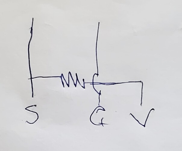
If you think that it is most likely the endstop issue, try adding a 1-1.5 kOhm pigtail (3 pin female connector on one end with a resistor between the two outer pins and wires from one one outer pin and center pin to a 2 pin male connector on the other end. MAKE SURE that the 3 pin connector is attached so that only the resistor (and not the resistor and wire) is touching the VCC pin on the board, or you can permanently damage it.

Alternatively you can solder a resistor to the underside of the board, or cut the trace to the LED (either of these options will void any possible warranty claim).
I’m saying that for the affected SKR Pro 1.2 boards, the circuit design is defective. Those may work as you describe for a while then fail, or may never work at all. All board in this state need rework or mitigation.

I’ve also seen- by inspection and test- boards that have a different design for this circuit, which does not have the defect. I’ve never seen one of those exhibit the bad behavior that we’re describing.

The affected boards were built with a design defect.

What I’m hearing is that somehow the defective design is either in active production again, or a big batch of bad boards has escaped somehow into distribution. That’s why I’m curious about build dates and lot numbers.

I’m not defending BTT, it’s very clear they have and maybe still are shipping some defective SKR Pro 1.2s.

All manufacturers do this differently. It should be visible on the board itself with a printed or labeled or marked set of information on the board. When I get a chance, I’ll pull a couple of my SKRs out and see if I can get decent pictures to share.

In the meantime- do you have pictures to share of your new board?

We should probably move this sub-discussion into a new thread, as we’ve hijacked Rusty Bumblebee’s thread.

To that point- @Rusty_Bumblebee - to take next steps with your setup, we need to see M119 results as I noted above and in the quote below.

Pull an M119 while the affected endstop is not triggered, then hold it triggered and pull annother M119. Share those with us. You should probably repeat those several times and if you get inconsistent results note what those are.
Edit to add- also note what the LED does in each step.

I suspect you do have one of the affected boards, and this is one way to verify that. Comparing LED behavior to M119 behavior is the clear indication that you have an affected board with the bad endstop circuit design.

1 Like

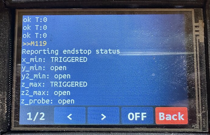
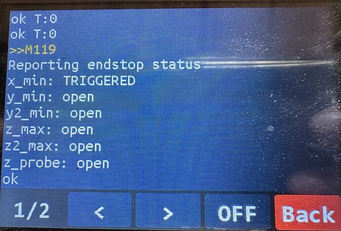
I have tested this by giving it a m119 with me manually triggering the zstop.

When I trigger it manually the led on the board lights up without fail.

But when I check with m119 this is the result when I trigger z1 manually

And this when I trigger z2 manually

So I guess I have some soldering to do.

“If you think that it is most likely the endstop issue, try adding a 1-1.5 kOhm pigtail (3 pin female connector on one end with a resistor between the two outer pins and wires from one one outer pin and center pin to a 2 pin male connector on the other end. MAKE SURE that the 3 pin connector is attached so that only the resistor (and not the resistor and wire) is touching the VCC pin on the board, or you can permanently damage it.”

is there a picture of how to do this, I think i understand what you mean but blowing up the board would suck so I rather be certain.

If I understand correct the porpoise is to add 1.5kOhm to one of the wires to the board adding the extra resistance to the circuit? if so, couldn’t I just solder that resistor somewhere in the wire?

Rusty

yeah thats not the problem, it gets triggerd just fine

I will see if I can find what batch this board is. I build my machine in
January and ordered the parts from BTT in december.

on the Box it says 1020000209 Bigtreetech SKR Pro V1.2 B/C: 2023 8. 31

From the V1 SKR Docs page,

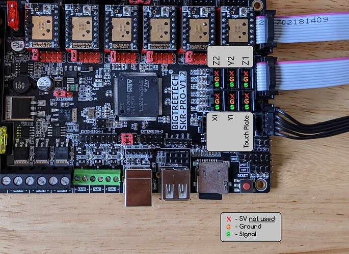
You want to use the resistor to jumper the red X (5V VCC) to the green dot (Signal). The switch leads from the switch still go from Signal to Ground (yellow G). Never allow Ground and 5V VCC to connect to each other (which would happen if you reversed the 3 pin female connector so that the resistor and Signal wire were touching VCC instead of Signal). Hope that is clear enough,

Here is a post that shows how to make the pigtail (although he used a 3 pin male connector with only 2 pins, instead of a 2 pin connector). He doesn’t discuss the importance of making sure it is connected to the board properly, but that is critical.

Here is another post that shows the pigtails made just a bit differently (personally I like this version better, the longer leads allow you to hide the connection under the board)

1 Like

Ah my old electrician brain finally understands ( I haven’t been doing anything electrical since I left school and later got a degree in business management so this is no dig at my teachers)
And I never really was into electronics anyway.

We want to add some extra charge to the signal so when z is triggered we don’t get signal to ground but signal + (whatever is left after the resistor) to ground so the signal is boosted.

Does it matter what wattage the resistor is? I have some 1/2w 1.5kohm laying around.

Yes, you understand this correctly. We want a stronger pull up.

It’ll work fine. Higher power rated than you need, but since you have them, use them.

Edit- if you have to have 1K laying around, that might be a slightly better option- but 1.5K ohm has worked for others.

1 Like

Note that one of those linked threads shows an incorrectly built pigtail.
You want it to look like this electrically (picture copied from later in that thread)

2 Likes

After getting my soldering iron out of storage

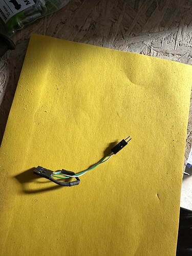
I made this

And now it’s working perfectly!

Thanks guys this community is really great and helpful!

Finally I can start using my cnc with confidence, but first flatting the top!

2 Likes