Sorry for being a goof saying something that might be obvious and something that you already don’t consider an issue - but leaving electronics on the outside of the static bags can shortcut things…
2 Likes
![]()
![]()
What am I not seeing??? AHAHAHAH that is crazy and awesome at the same time.
NP at all. I have heard that it’s possible, but in my 25+ years dealing with electronics both professionally and in hobbies, I have yet to release the blue smoke due to powering it up on top of an anti-static bag (knock on all of the wood). I have, however, smoked very expensive equipment setting it down on an unclean surface where I may or may not have left something highly conductive “sprinkled” about. Either way, I appreciate the concern. ![]()
Glad you took it as a friendly concern, and not as gatekeeping! You have far more experience than me, that’s for sure. But frying things are always interesting, especially if it’s high voltage and your own fingers are involved…
1 Like
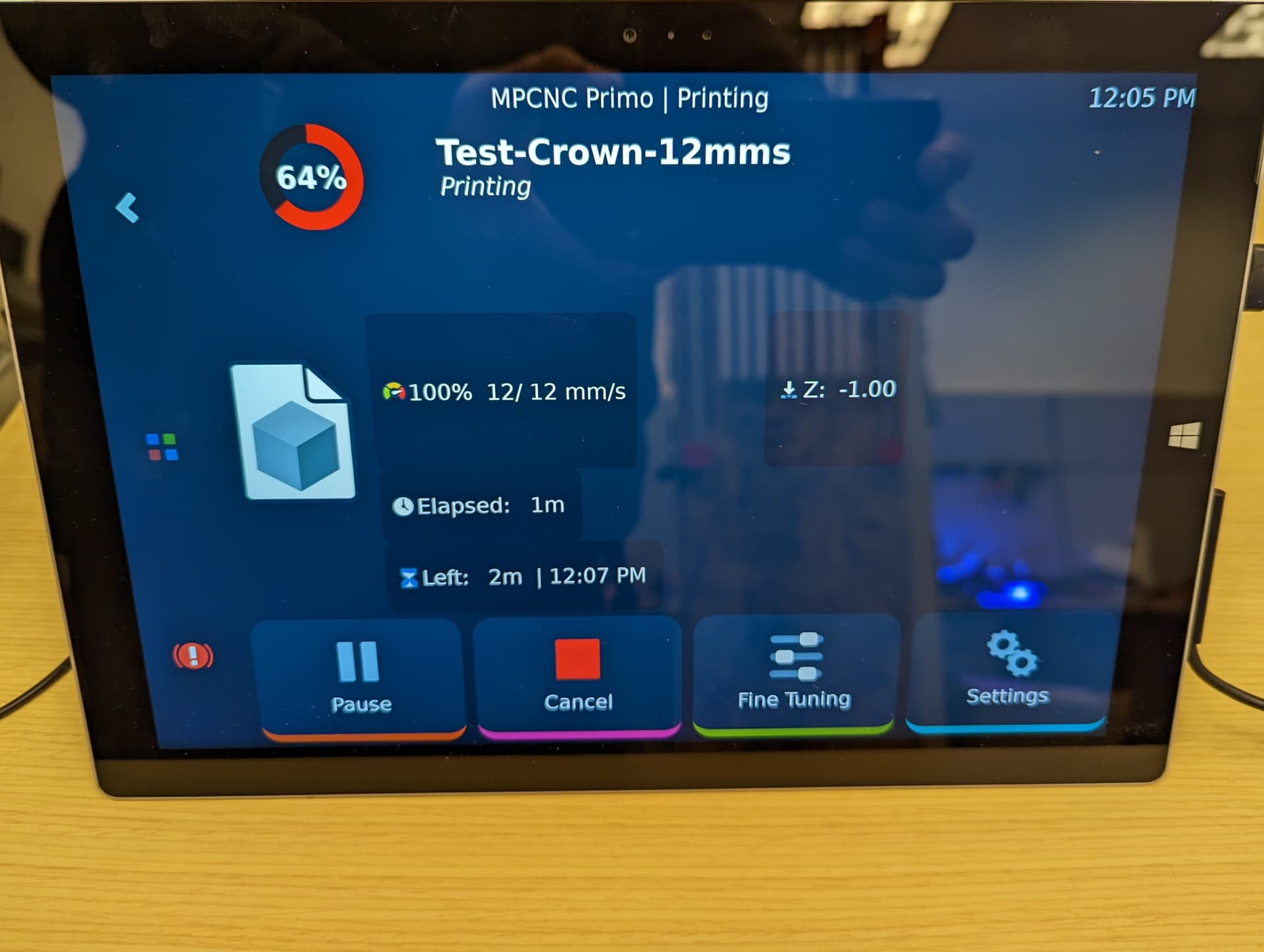
That is an old Microsoft Surface Pro 3 “laptop” running Ubuntu, Klipper, and KlipperScreen. The usual pairing is a Raspberry Pi running a similar stack, but Klipper in all of its awesomeness can run on most Linux distros despite the CPU arch. After I get things moving, I was going to see about customizing KlipperScreen for CNC specific goodness.
3 Likes
The base Klipper config seems to be working. I guess I’ll need to start cabling soon. I happened to find an old broken tape measure in the office today. I think I’m going to give the TMT a try. Since I’m going with sensorless homing for X/Y, I may be able to get away with stranded ethernet cables.
As far as Klipper config standardization for the Primo, I think we can get away with standard pin alias naming in the printer.cfg, then creating a [board_pins] aliases file for each of the “tested” controllers. New users would just need to determine the /dev/serial/by-id/ path to the controller (easy) and modify the [include my_board_pins.cfg] to the board they are using. Assuming all steppers and end stops are connected to the defined ports on the controller, it should just work.

1 Like
Too small!
1 Like
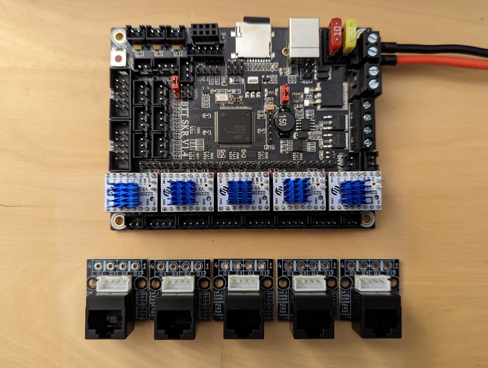
I found these on eBay. I just bought 10 so I’ll incorporate 5 in the controller case and strap the other 5 to some form of stepper mount.
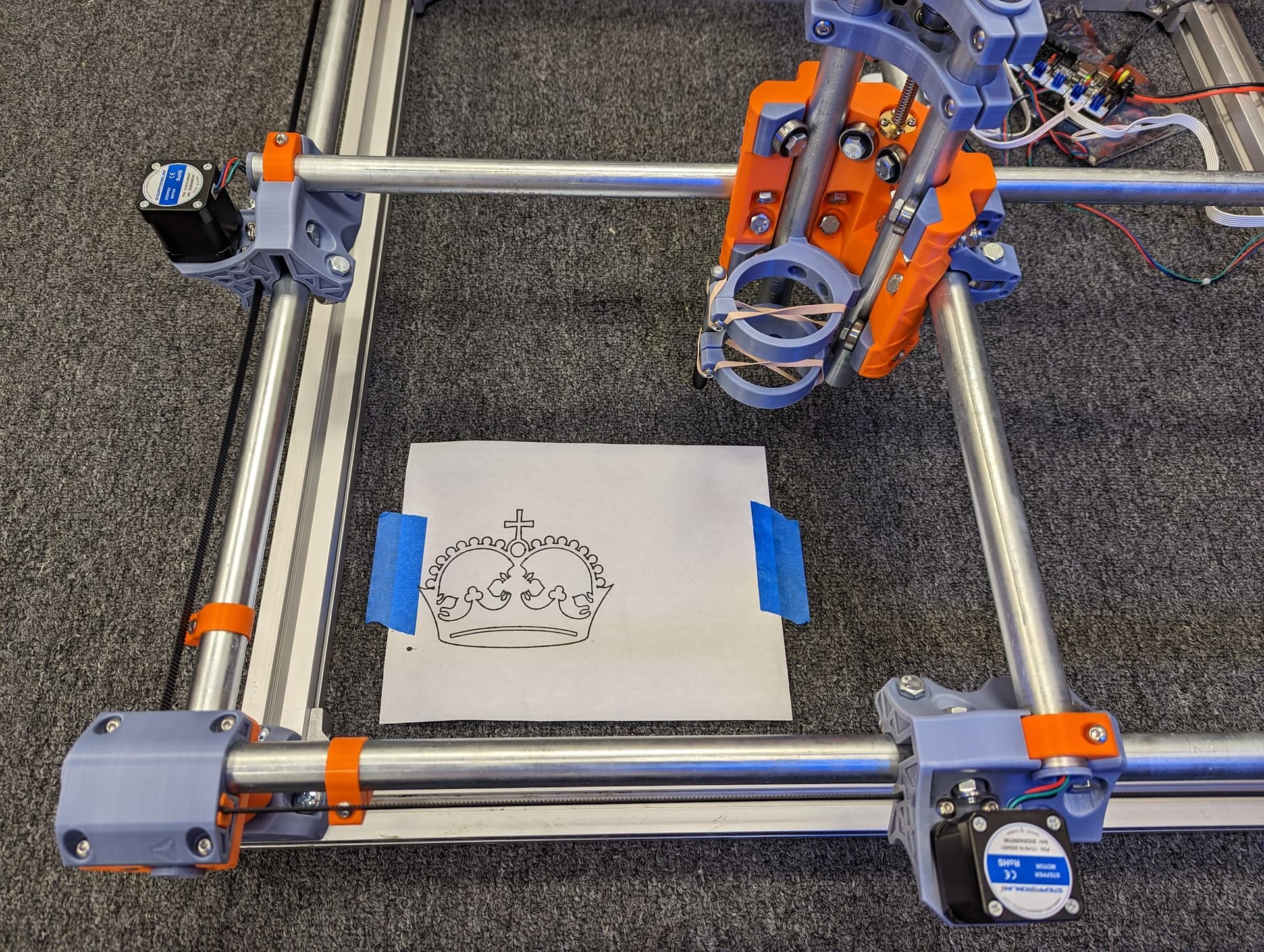
Lift off! Quick and dirty cabling while I wait for my RJ45 adapters. So far, I just needed to alias G00 and G01 to G0 and G1 respectively.
[gcode_macro G00]
description: CNC Alias for G00
gcode: G0 {rawparams}

[gcode_macro G01]
description: CNC Alias for G01
gcode: G1 {rawparams}
5 Likes
I think I have sensorless homing dialed in on the X/Y axis. I should probably read more on how to “home” Z before I break something. ![]()
It only gets better from here. Congratulations ![]() !
!
1 Like
That looks awesome. My voron has fluidd on it and I really like that. Is the klipper screen software something like that? Does that also serve up the webpage you have a picture of?
KlipperScreen is an addon like Fluidd or Mainsail (web UI pictured above). It runs on the Klipper host system. If you run a Raspberry Pi on your Voron, they sell small 5-in screens that plug into the display port on the Pi you can use for KlipperScreen.
A lot of folks that use Klipper do not know that it’s way more than just firmware, it’s a full framework for motion and control systems. “Klipper” is the firmware that runs on the microcontroller that allows it to talk to “Klippy”. Klippy is the brains of the stack. It’s the Linux daemon that handles the complex motion planning, and juggles 1 or more of the Klipper MCUs. Then we have “Moonraker” as the API interface to Klippy. This is what UI interfaces like Fluidd, Mainsail, and KlipperScreen use to “talk” to Klippy. If you can’t tell, I’m a fan. ![]()
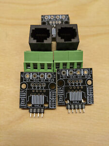
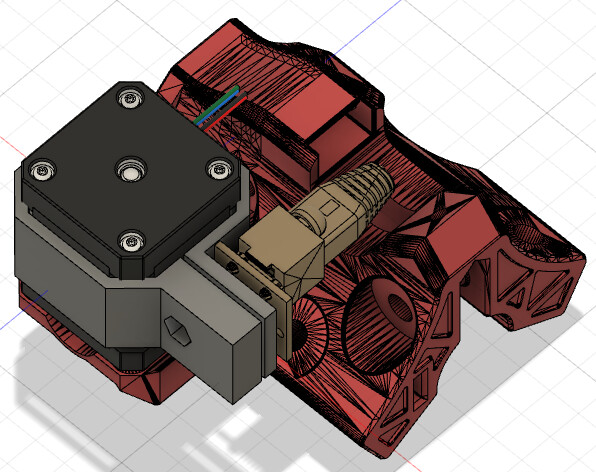
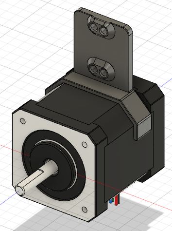
My RJ54 stepper PCBs showed up today. I thought I’d try to model mounting solutions. The RJ45 socket entry is perpendicular to the PCB. I plan on keeping the original stepper wire intact, coiling it around the stepper body, or tucking it between the motor and the truck bodies. The ethernet cable may be the deciding factor as to how I mount this stuff.
Option 1, PCB parallel with the stepper body.
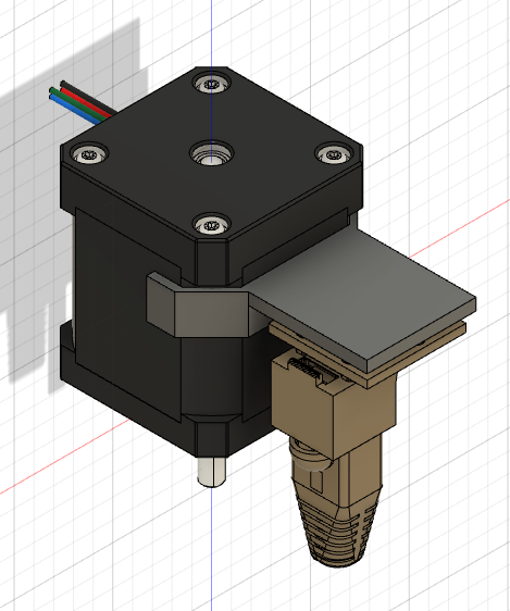
Option 2, a clamp mount holding the PCB so that the port faces the tube entry.
1 Like
#2 is awesome, or maybe even pointed down so no crud builds up in the socket?
1 Like
I’m still debating over the connection type(s). The PCB is pretty versatile. On the stepper end, either straight or right-angle pins depending on the final orientation of the PCB.
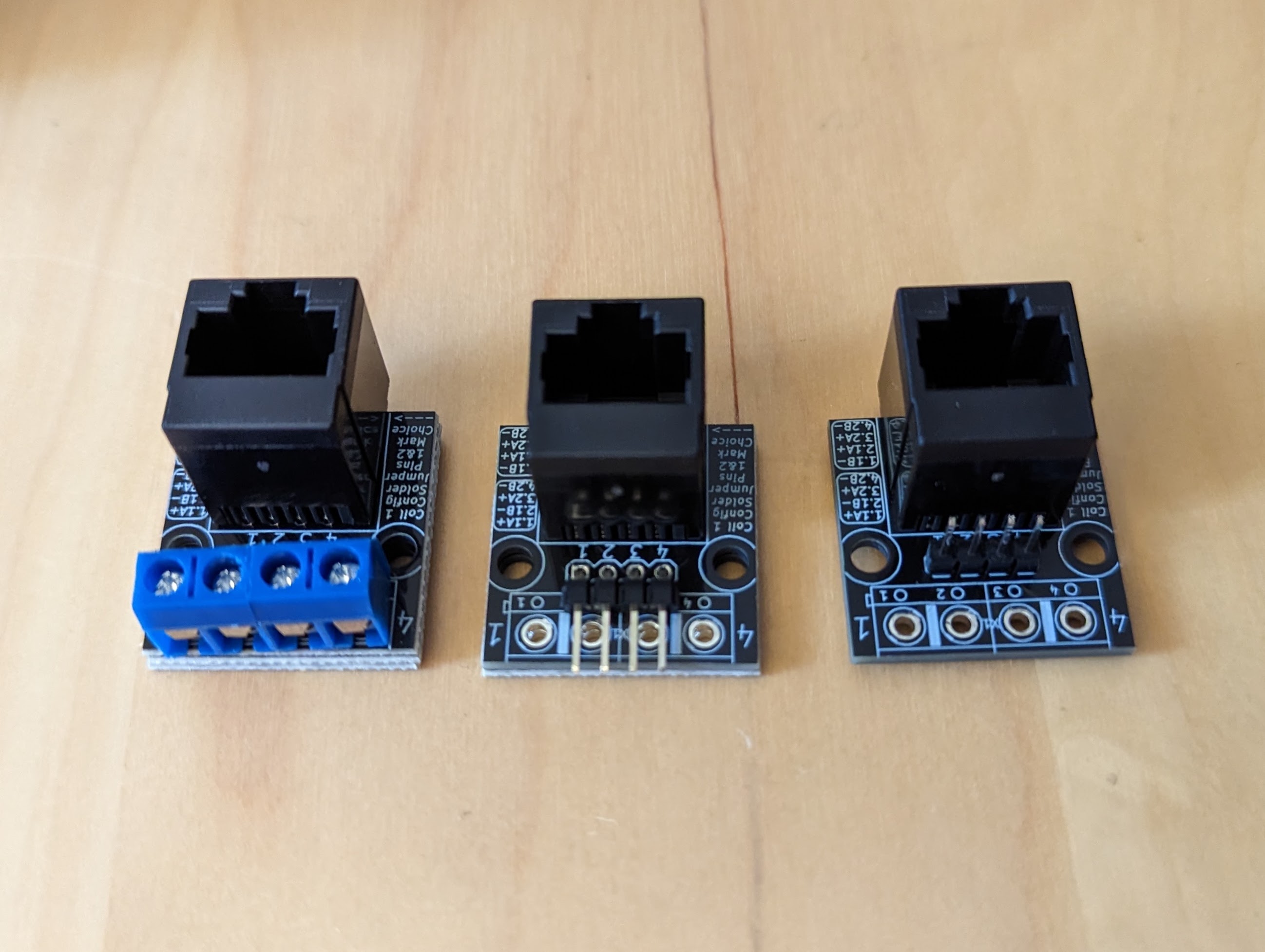
On the controller side, I was thinking of using 4-pin female JST sockets and male-to-male jumpers. There is also the option to either solder the jumper to the PCB or use terminal blocks. I feel like the terminal blocks will add too much bulk so I’m leaning toward the JST sockets.
2 Likes
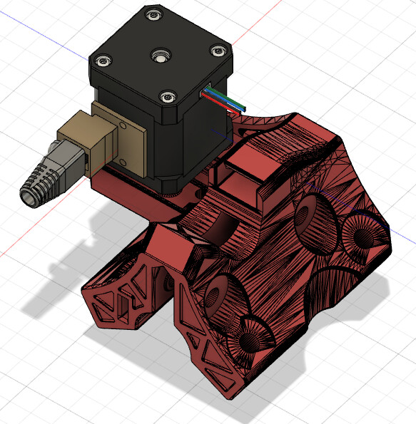
Instead of a full wraparound design, I’m thinking of a simpler zip-tied mount. I envision a downfacing mount for the X/Y steppers and up facing for the Z stepper.
2 Likes
I think this should cover all required orientations. Since the PCB’s mounting holes are offset from the center, I can cover 180-degree rotation of the board as needed.
2 Likes
A word of caution: I haven’t seen anyone mention in this thread, but make sure that you get stranded RJ45 cables for your stepper motors. Solid core Cat5 or Cat6 wires will fatigue and fail being repeatedly bent even over a drag chain radius. If you use stranded patch cable, you should be fine, but multiple people have reported solid core wires failing over time. This happens in weird ways that can be difficult to diagnose, so you want to avoid the problem in the first place.
2 Likes