Oh absolutely. Depending on the bend radius, I do not think a solid core cable wouldn’t last long. The current plan is to use off-the-shelf patch cables that can be quickly swapped out should one suffer internal breakage. Thanks for the tip though.
1 Like
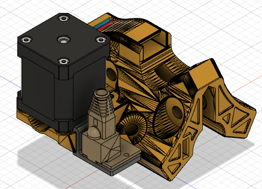
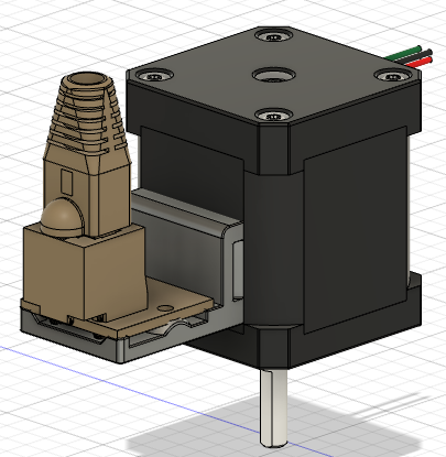
It seems to fit a little better facing up.

I feel like the ideal placement would be low on the truck. Non-prismatic imports of the truck in Fusion 360 would be a pain to work with. Then I would need to re-print all 4 and that’s no fun. Back to the drawing board.
1 Like
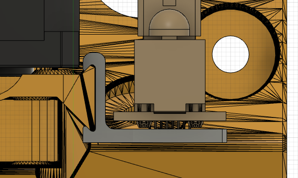
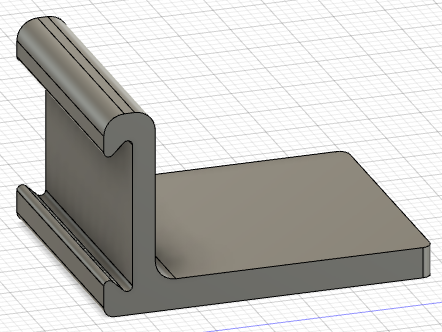
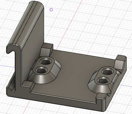
2nd take. I’m thinking of some kind of slide on clamp to take advantage of the 45-degree tapers on the stepper mount. In this config, it’s still ambidextrous and should be printable on its side without supports.
Close up.
Wish me luck ![]()
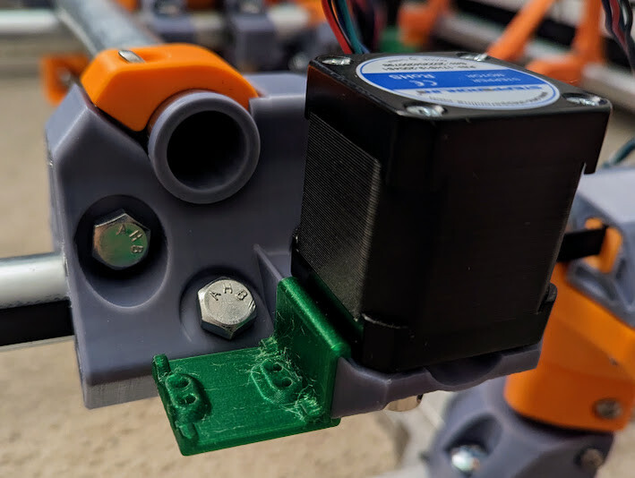
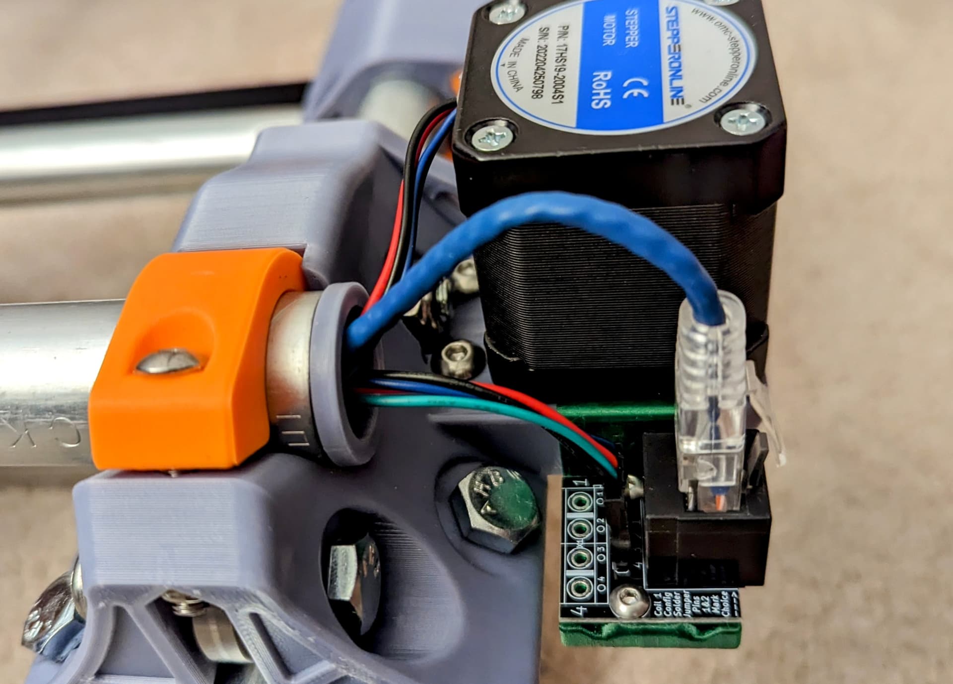
This worked better than I would have thought. It’s a very snug fit so your printer tolerances have to be spot on. Pardon the stringy PETG. Its what was on the printer already. ![]()
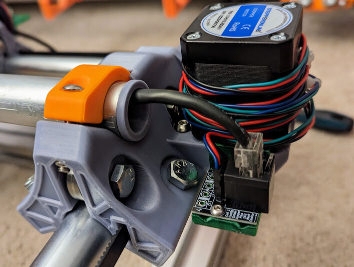
This is not elegant by any means, but it works. If there is enough room in the tube, I may just stuff the excess stepper wire in and then double back to the PCB.
The alignment seems to work out well.
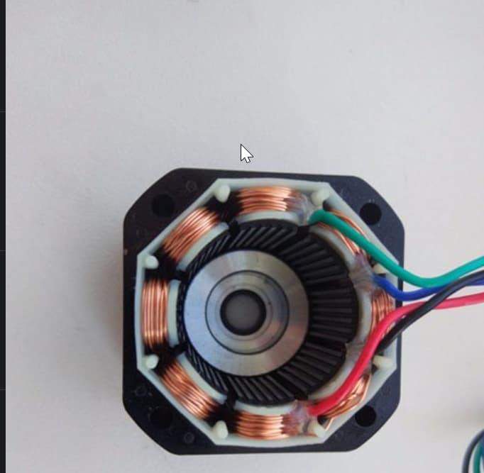
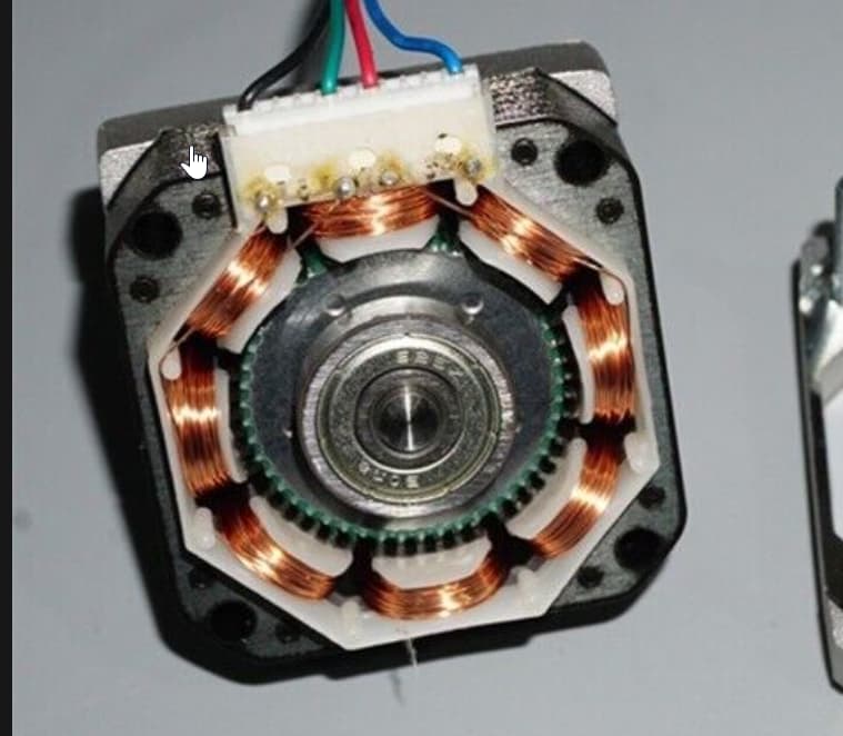
That looks awesome. I have a few steppers that come with pins for connectors rather than the 4 cable mess. This has me wondering if you could make a PCB that goes inside the stepper that solders on to the internals. I found some images online of the different connection styles. That would have you violating your steppers but it would look slick.
1 Like
The ones with pins are (as I’ve seen) JST XH 6 pin conectors with the pairs as pins 1-4 and 3-6.
I’ve made up extension cables before.
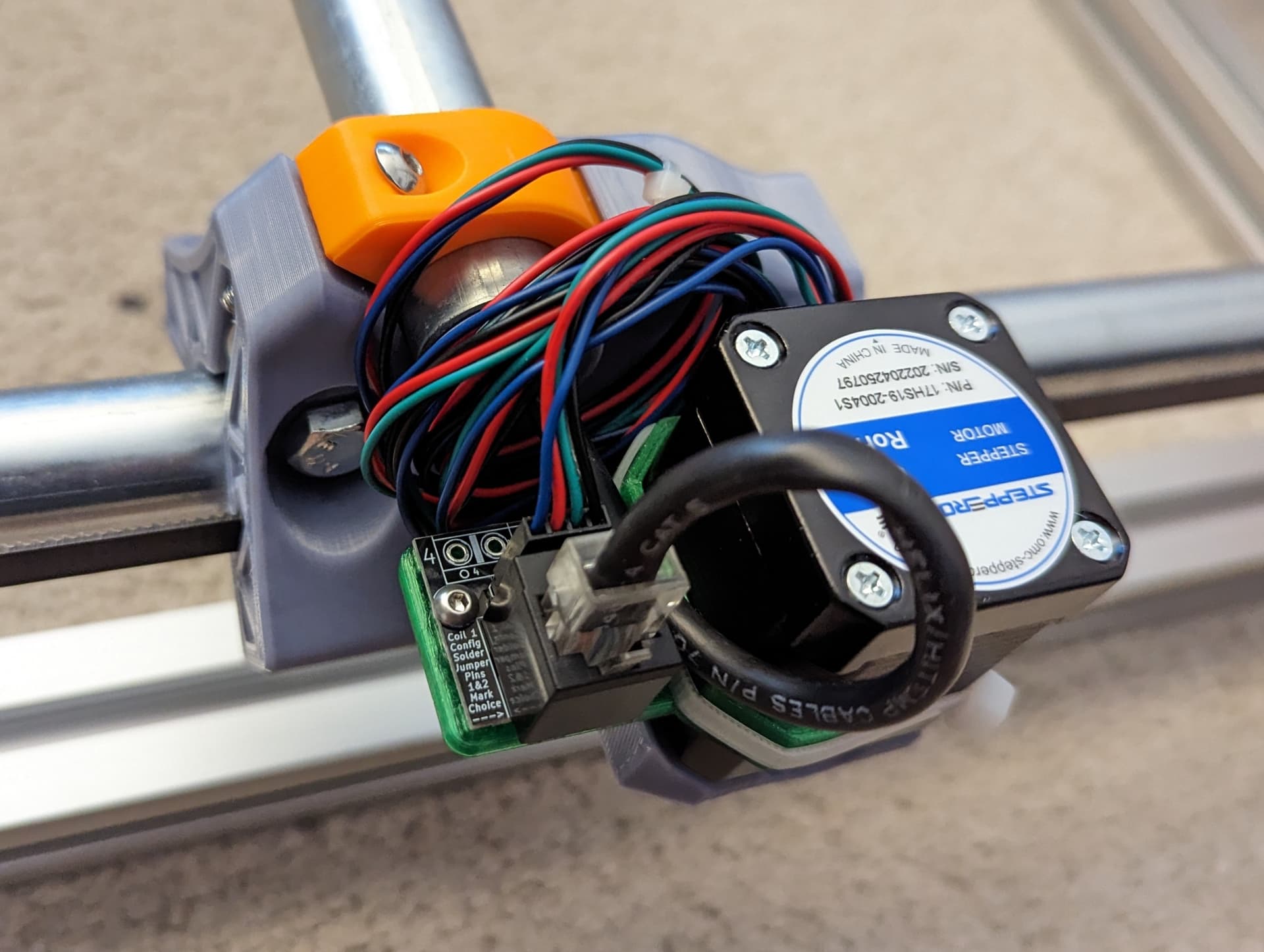
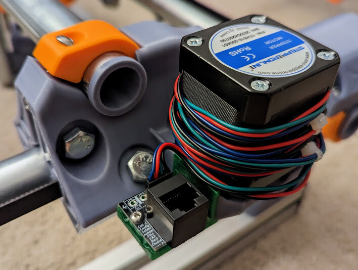
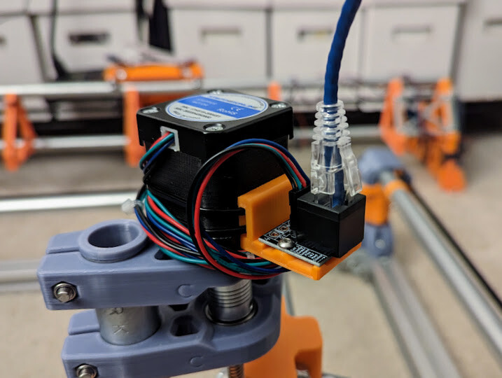
AB2Tech happened to have this little puppy. ![]()
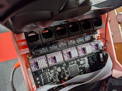
It connected directly to the JST connections on the SKR 1.4. Now I’m debating on going with this PCB or a non-linear arrangement.
Have a link to that adapter board?
I’ve asked AB2Tech to make an official listing for them. When I have the link, I’ll post it here.
The listing is up if you are still interested. If you want both the controller side PCB and the stepper side (receiver) PCB, you can select them in the listing.
When I receive my PCB, I’ll work on a case to accommodate the SKR 1.3/4 and the RJ45 bits.
2 Likes
Any idea what the current capabilities of those wires and connectors that plug in carry are? I thought we were pretty borderline when people were using those a while back.
From the cable perspective, CAT6 cables typically use 24AWG. With the doubling of the conductors per stepper pin, that should provide ~1200mA per pin. Even with lesser quality CAT5 with 26AWG wires, we net ~720mA per pin.
I’m not sure about the PCB trace width, but they seem very ample to my uneducated eye. The interface headers for the controller side PCB are SLW-104-01-T-S. Per the datasheet, they support up to 5.2A per pin.
Have folks burnt up ethernet cables in the past?
Per pin or per pair?
It all sounds good, Really I am just making sure you took a look at it because I know this was a huge ask in the past and for some reason I don’t remember we are not doing it today.
We run between 800mA and 1100mA for the most part. Not sure what that translates per pin and for the less than 4’ we run I am sure we are safe. If you are comfortable, I am comfortable.
Also, make sure you get stranded, solid wire will break.
1 Like
The PCB combines ethernet pin pares into stepper pins, 2 to 1, so we get the combined amperage potential of 2x24AWG conductors per stepper pin. I’m no expert (he said for the 28736482nd time), but that should give us 1.2A per stepper phase. I’m more than willing to take one for the team and try it out. ![]()
I work with actual EEs, so maybe I’ll pass it by them next week. ![]()
1 Like
That would be great to know, it would save a ton in custom wires if these ports were just built into the boards.
1 Like
Absolutely. As the project founder/creator, it may be worth reaching out AB2Tech directly. They had mentioned that they also run these on a Lowrider so they have firsthand experience.
I finally had some time to work on things. This zip-tie mount is on the printer right now, I’ll update with real pics and maybe a printables link once I have tested everything.
1 Like
It fits well. A wide slot for more than 1 zip tie if needed. There might be enough room for a TMT mount, eventually.
Printables link:
https://www.printables.com/model/480725