Repeat V2?

Dug into this some more and figured out how we can. Extended the script @ v1engineering-mods/mp3dp-v4/scripts/export-components.py at main · aaronse/v1engineering-mods · GitHub to bulk export .STL files, optionally rotating for 3D Printing based on Body name tweaks. Will share usage details in separate topic…

Edit: Created video and topic over at Fusion 360 - Bulk export parts to .STL files oriented for 3D Printing

1 Like

Cool!

Added the v4.1 parts to Printables

https://www.printables.com/model/282346-mp3dp-v41

4 Likes

Any specific changes in V4.1? I have all the original V4 parts, any parts that I should replace?

1 Like

The new hemera fan shroud is nice, The Z belt holders are a bit better. Other than that if your idlers fit, no need to reprint.

2 Likes

Everything fits great as is, I did a bit of sanding on the parts originally to make the idlers fit.

Is the new shroud just cut in half essentially? Appears to be the same design other than only requiring two screws to mount instead of the 4.

1 Like

No, I increased the volume of the air chamber, and nozzles. Hopefully leading to less back pressure and more air flow. From a blow the fan on the face test it seemed to be better.

3 Likes

This is all the data I need. I’m convinced. Printing the new one now.

1 Like

Q: Noticed rack mounted filament spools in…

Curious how/where people are mounting spools to their MP3DP v4 builds, especially with enclosure panels. Back would be inconvenient, so guessing Top/side? Am liking the idea of filament picking up residual heat from the enclosure panels.

1 Like

For RMRRF, I think I will mount my spool to the side. I will be working on that mount soon. But there is room to add a mount in a few places. In those V3’s you can see a hole I had cut in the side, I actually put the spools there half in half out for a while.

1 Like

I tried to open the latest Fusion 360 file for the printer in Fusion, and struck out. Apparently my Fusion install is not the latest, so I’m not allowed to open the files. Also my laptop / MacOS is too old to install the latest version of Fusion. So, I am not able to edit the parameters and not able to open or edit the F360 file(s). I was able to download and open the SketchUp file, but obviously there would not be any parameter-based changing there. :-/

Is there any chance someone that can open it could possibly save it as compatible for an older version of Fusion 360? My version is 2.0.11680.

UPDATE:

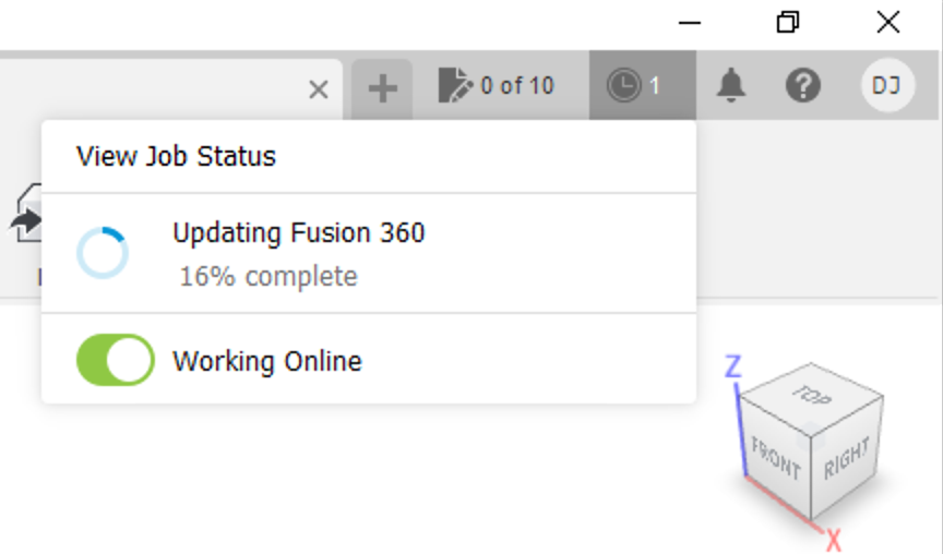
Possibly good news. I remembered I had a Windows version of F360 in a virtual machine of Windows 10, and I tried opening it there. That install is still too old, but it should be updatable, so I will wait for the update to complete and try again!

UPDATE - good and “gooder” and not quite as good:

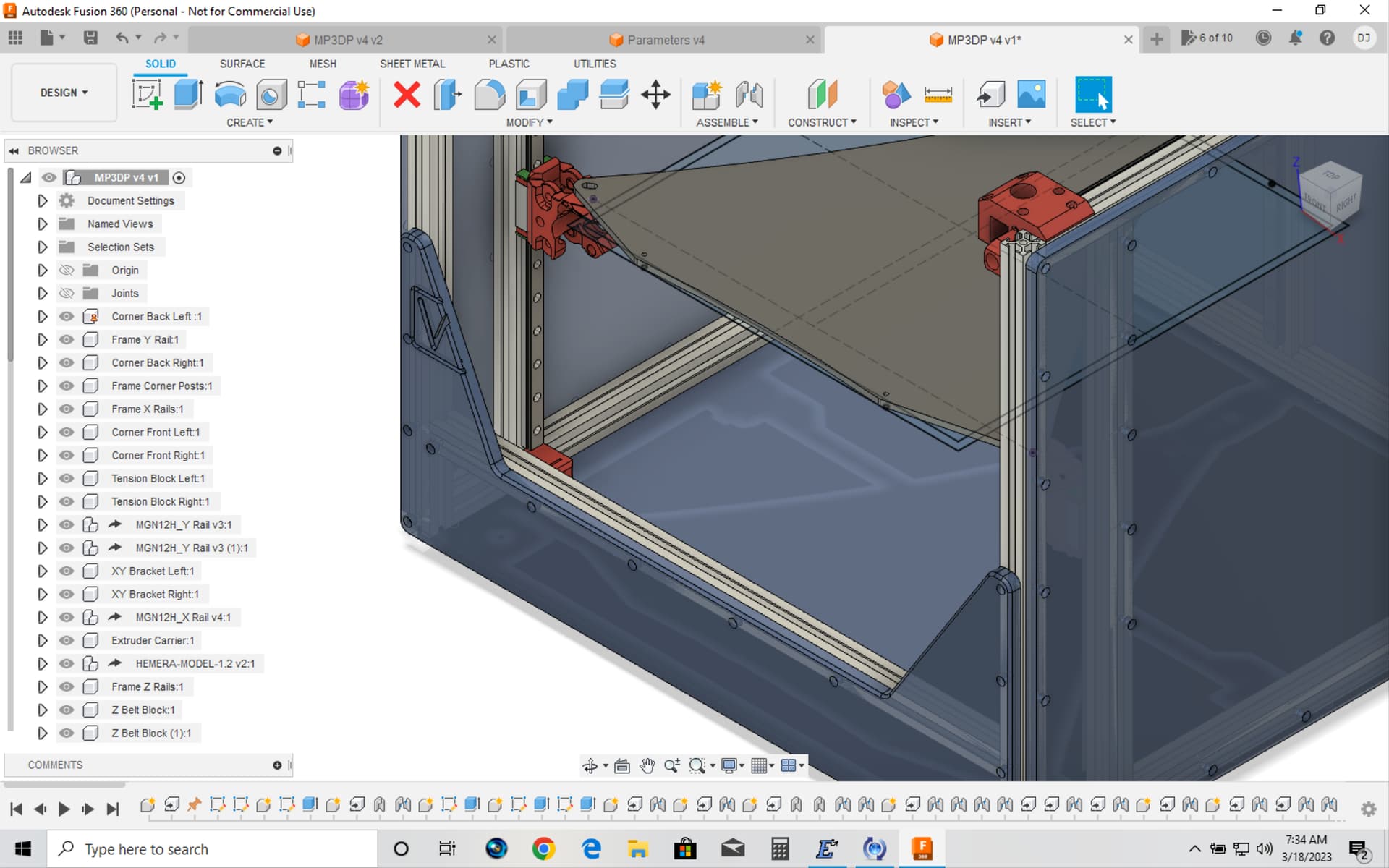
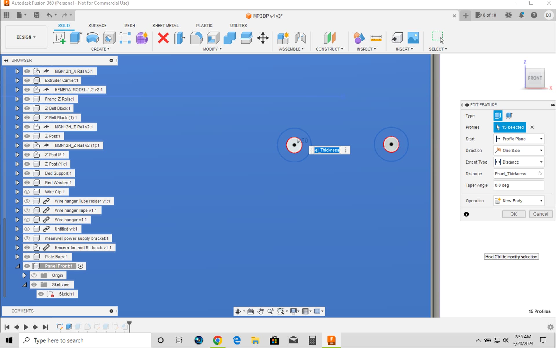
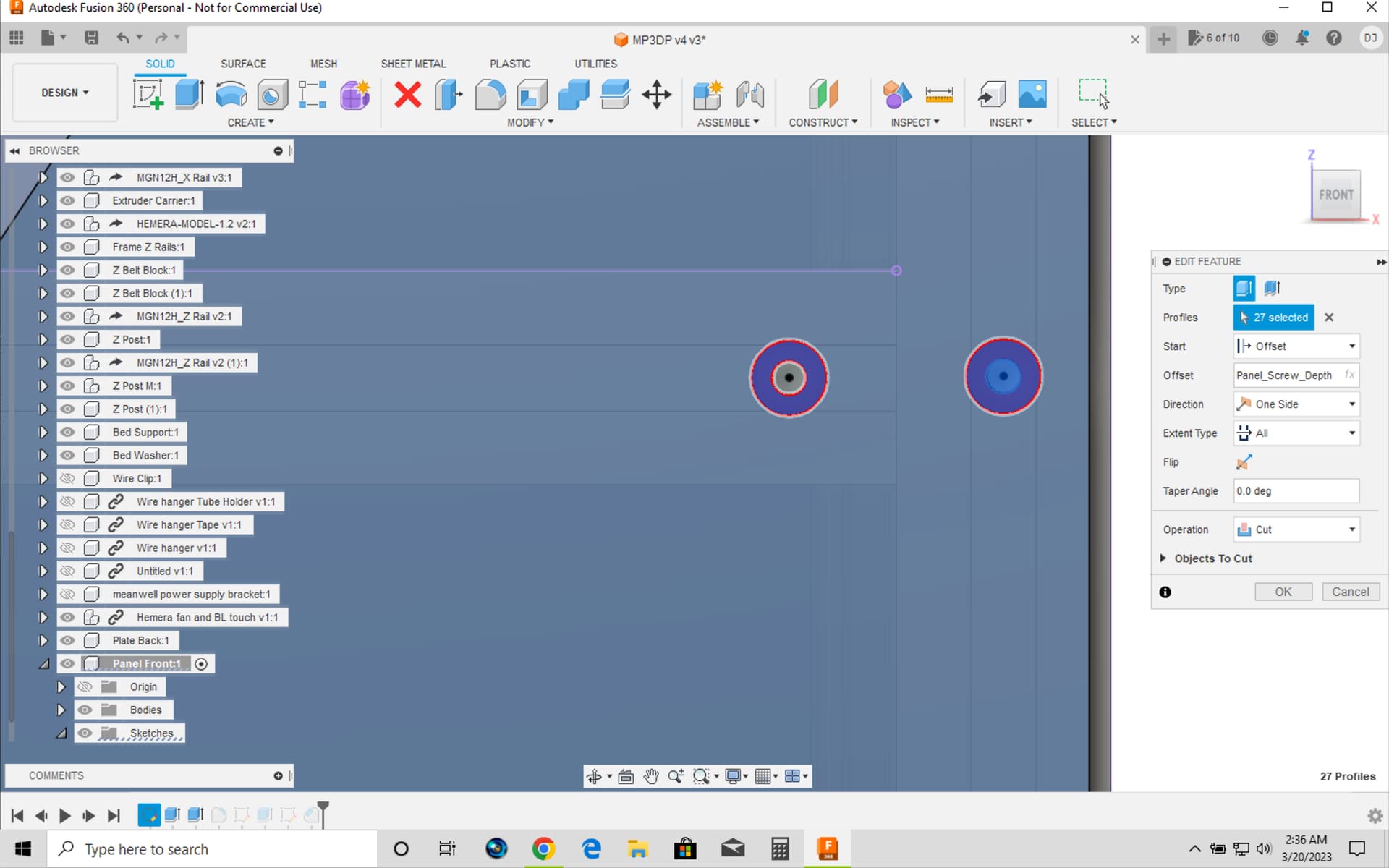
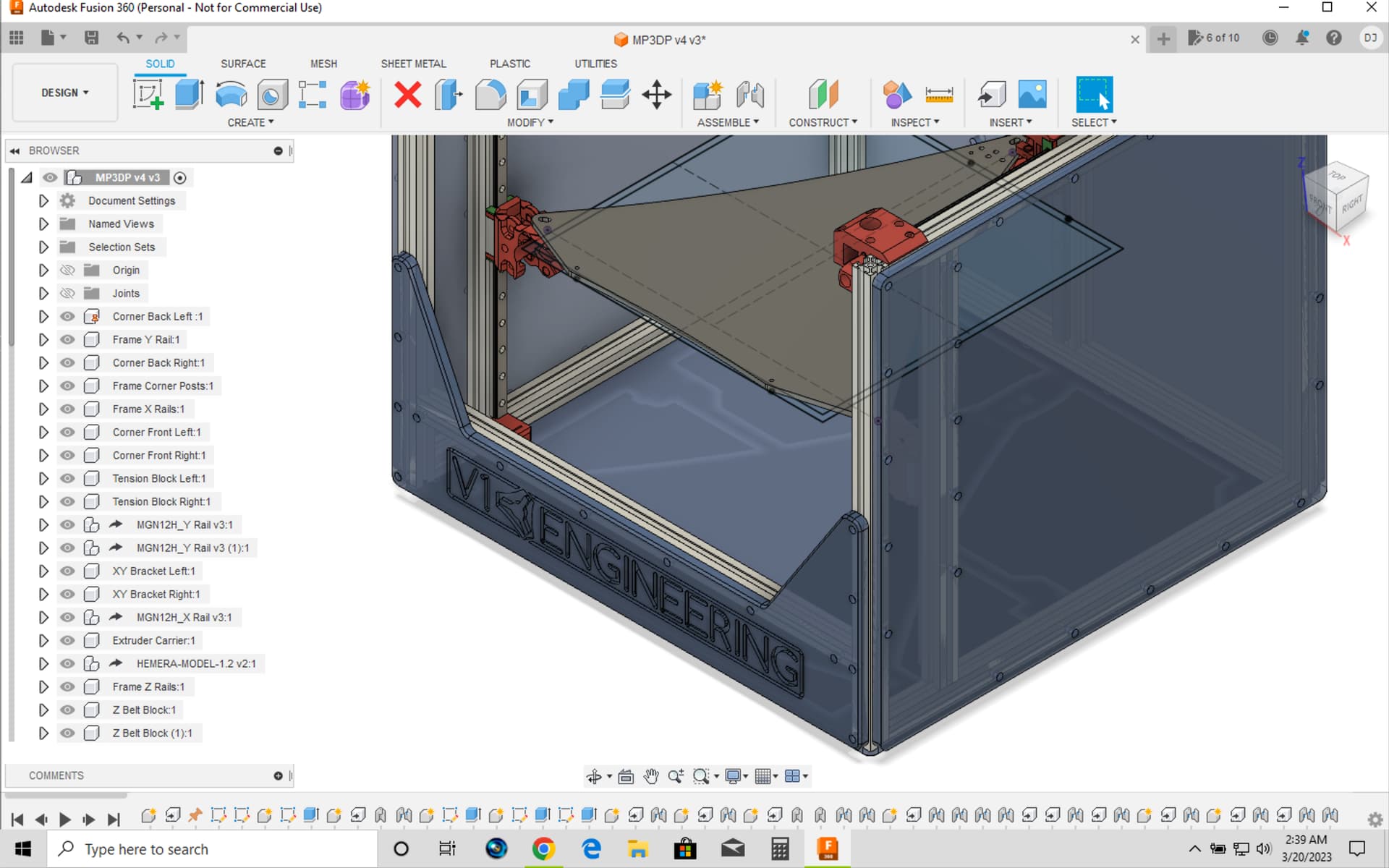
Good: OK, I was able to update F360, and I was able to open the params file and edit it (for now trying 325 x 325 x 325), and I was able to open the main file with the printer design.

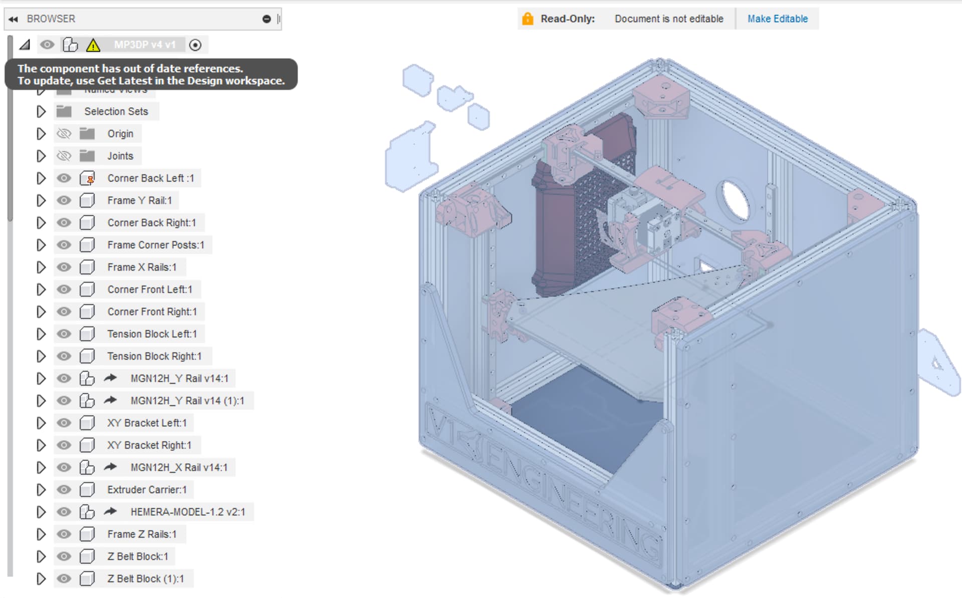
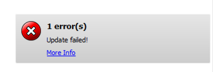
Gooder: It said I have one component that is “out of date” but I was able update. However, notice that this worked only after saving a copy of the main file, and reopening it. Until then, I got errors when trying to update the out of date component

What it looked like before saving a copy of the main file, and reopening it:

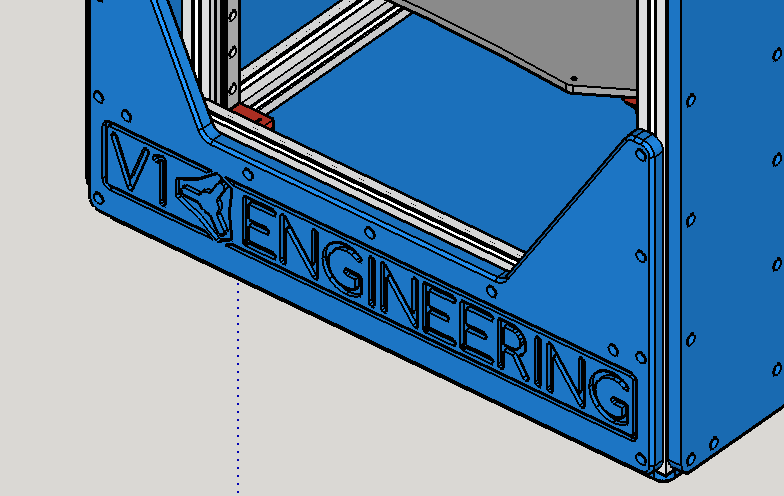
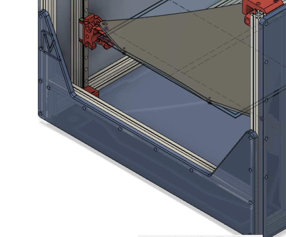
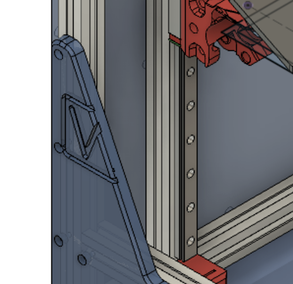
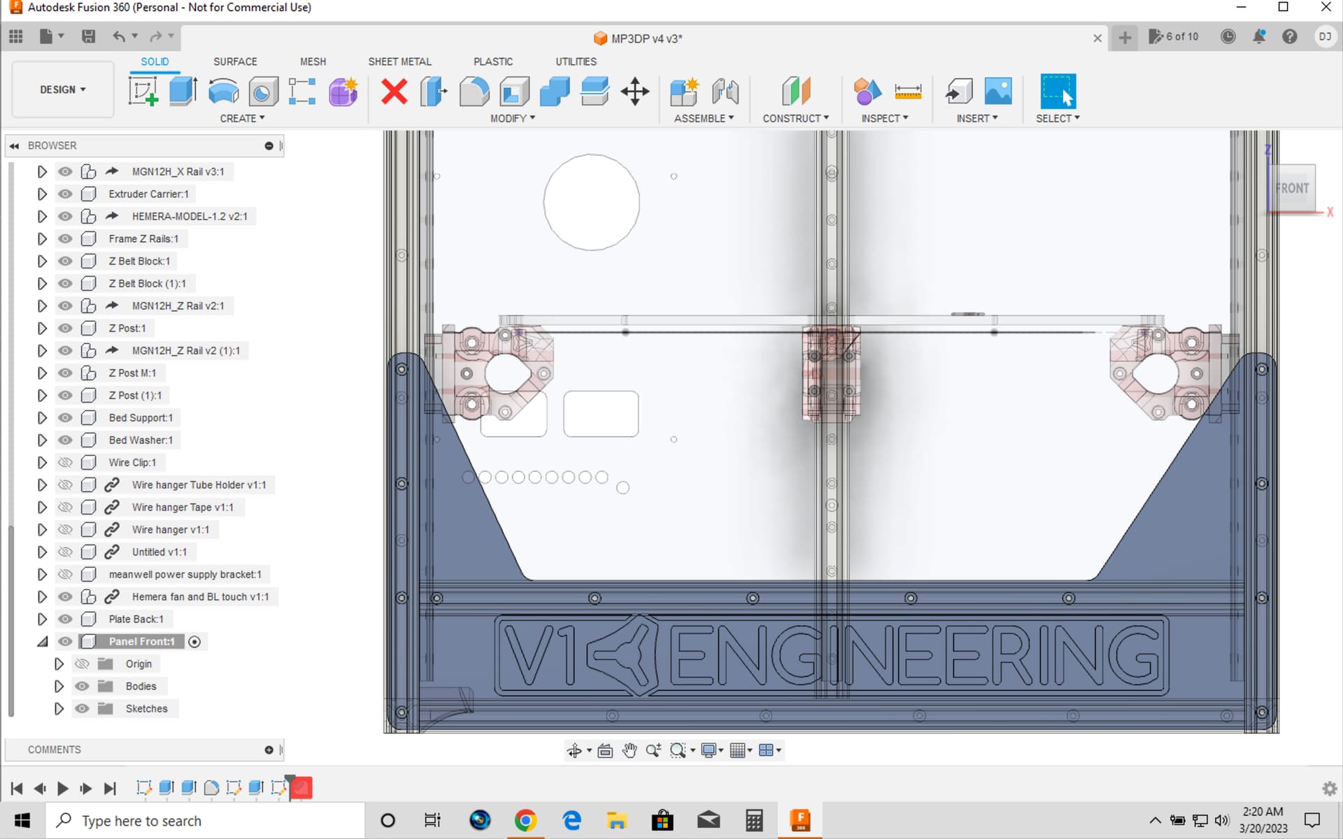
Not quite as good: The front enclosure panel, prior to editing params and updating the component, had a V1 Engineering logo cut in, across the bottom, but after the updates to params and component, the logo got raised up too high to work:

BEFORE editing params, saving, reopening, and updating the component (screen shot from SketchUp because I did not have any screen shot from Fusion from before):

AFTER editing params, saving, reopening, and updating the component:

Update:

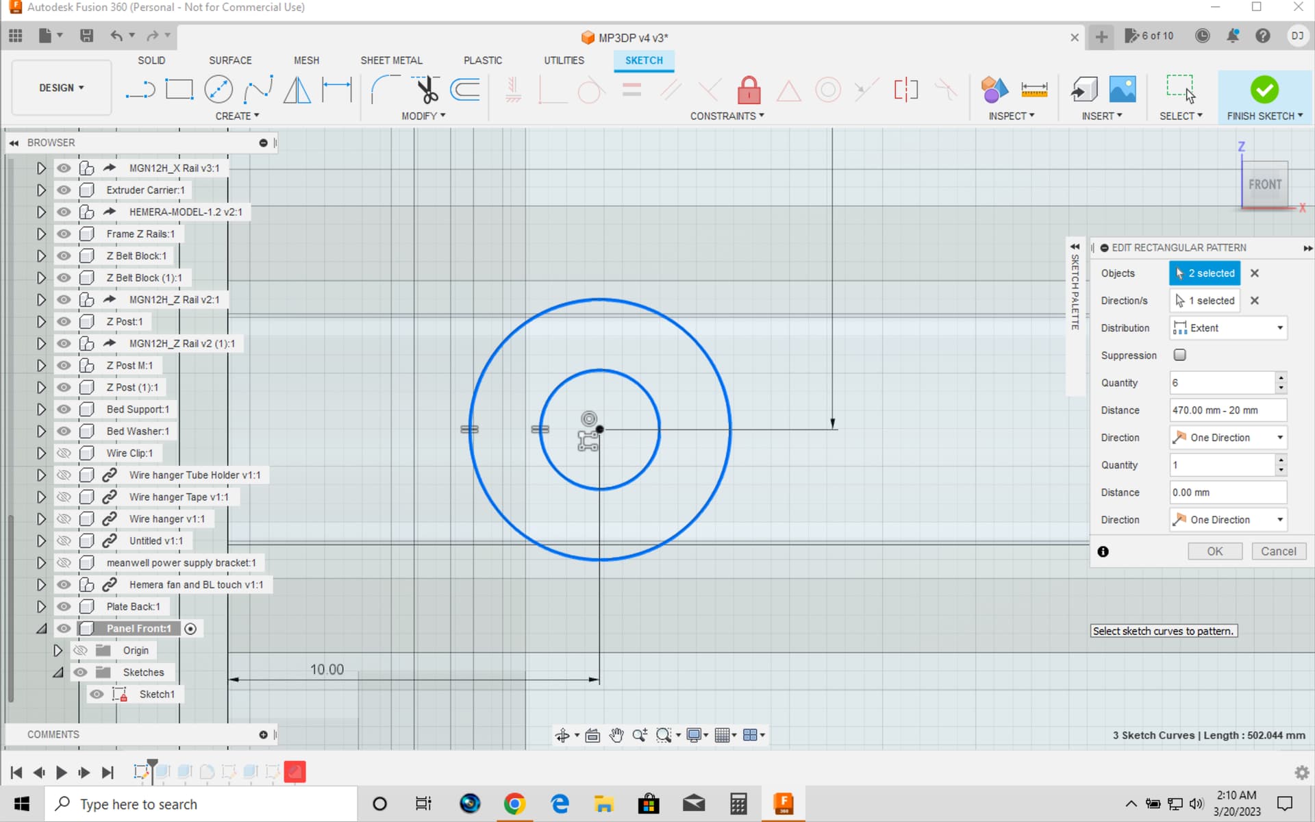
I manually moved the sketch that produces the V1E logo cut in, and it updated the cut in location to be better.

However, after later going through some details to get the X, Y, and Z linear rails to update to the length based on change to params ( as described in this post here: MP3DP v4 - Aza's build - #25 by DougJoseph ), the V1E logo placement when back to being out of place (I also note that I manually moved it, but did not add any constraints to its location):

Hey, based on these screen shots after I increased usable area from 200x200x200 to 325x325x325, it seems like the enclosure panels screw holes are not quite updating right. Am I correct on that?


How old are we talking? my Macbook Pro is 2012 and running the latest updates. Just have to run patchier software to make it work…but does work excellent

Hmmm okay the logo and holes (actually the panels themselves) are new. I knew the logo would not move but I have literally been changing that every day, no easy way to constrain it until I am happy with it and make it a pattern.

As for the holes…I will try to parameterize them a different way. I hoped they would update but the distance parameter for the pattern was wonky and I am not actually sure I can, so if I can not a a dynamic dimension there I will locate them individually.

1 Like

This is not the age of my laptop (which is a mid-2015 model) but the fact that I have a lot of expensive (one-time perpetual licensed) software on this laptop that will become useless if I update my MacOS by even one more version. So it’s actually about my MacOS’s age, not the laptop.

1 Like

Re. the plates, how would I modify where the hole spacing is happening?

I was able to start from scratch on the CAD files (Fusion 360), and change the global params from 200x200x200 up to 300x300x300. I moved the V1E logo back down onto the front plate.

Issue now is the hole placement on the front plate has a set of holes at the top that is keeping a chamfer operation from computing. These holes are also too close to the edge of the plate to do any good. See screen shot.

Edit the sketch, the pattern settings are here. Bottom left hole.

2 Likes

Thanks!!!

I know how to edit a sketch in normal circumstances, but I’m not yet familiar with pattern settings, and in this, it seems, a more complex pattern since (on the horizontal) the two outermost holes need to be a set distance from the edge and then the inner holes can be spaced apart evenly.

Will try to dig in and learn.

OK, so I figured out how to edit the “rectangular pattern” for both vertical and horizontal. It’s not a parametric driven pattern (yet?), as far as I can tell, so I just manually tweaked the numbers to get a decent result. For a “usable area” of 300 x 300 x 300, the following are the edits I am using for the front plate:

For the vertical, I changed the “rectangular pattern”'s distance from:

-226.465203293383 mm + 20 mm

down to:

-215.465203293383 mm + 20 mm

For the horizontal, I changed the “rectangular pattern”'s:

quantity increased to:

	6

distance increased to:

	470.00 mm - 20 mm

Below are some screen shots related to these changes.

The final result of the sketch is this:

However,

for some reason, the added hole in the edited horizontal pattern is not being cut in the solid body of the front plate. ???

Update

OK, so I had to edit two different extrude->cut entries in the timeline to get the extra screw hole added, and to get the counterbore well for that screw hole added. Screen shots below:

Now to just figure out any additional screw hole edits to the other plates.

I didn’t read through that, I have too many emails to get through.

The pattern spacing is based off the length of that panel. There is a button for measurement (which apparently is not parametric for some reason), hit it and the edge to do it dynamically.

Future readers, when I get some time I will try to change this so it is not needed. The MP3DP panels and logo’s I thought were just for my own personal use so I did not bother doing all the extra steps. I will go back and look through them at a later date.

2 Likes