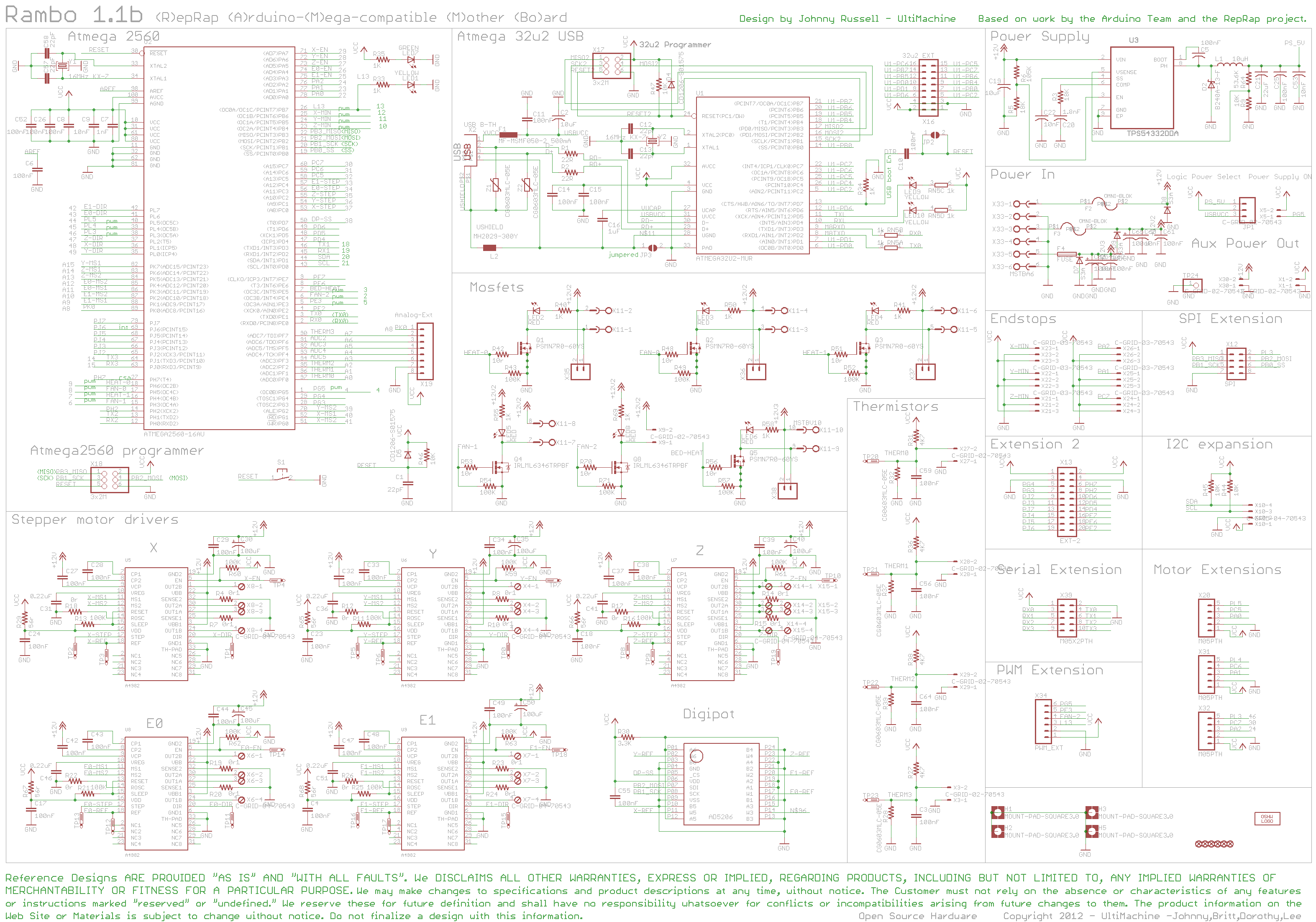
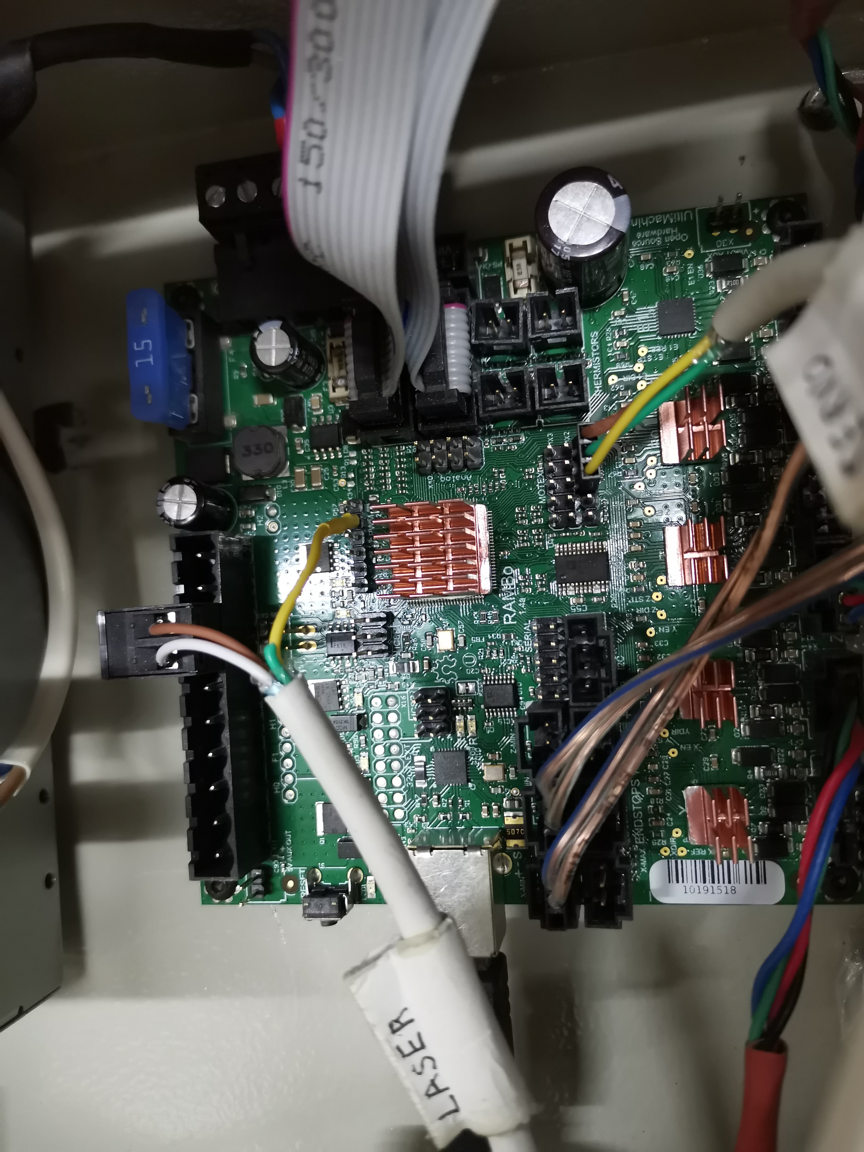
I need help to connect the laser to my lowrider on the rambo 1.4a board (https://www.aliexpress.com/item/32958037528.html?spm=a2g0s.9042311.0.0.27424c4dO6m4K7). I found several topics about lasers and a howto on the site, but all this concerns old rambo boards and lasers with a separate control board that only need 12V power. Maybe I do not understand something, but is there a clear instruction for connecting the laser pwm to the rambo 1.4a board? I will add a photo of my laser and my board.
For not to multiply topics: I have almost finished the work necessary for the airbrush module for my lowrider. For this job, I need to connect a servo machine to control the opening of the air supply valve. I found articles about connecting servo to the old version of rambo (https://3dprintboard.com/showthread.php?9335-Rambo-Servo-Setup-for-Auto-Bed-Leveling-for-Noobs) but in my version these contacts are located otherwise. I do not want to burn something, someone will help with this issue as well?
I have never used a servo on theses boards but you can have a look at the firmware and pinouts to get that working, both need to be edited for a servo.
I understood my laser 12v - this means I have to connect it to the 12v fan pins. Does this mean that I only use 2 wires + and -? I thought that the control is carried out through 3 wire PWM …
Direct me, in what config is the pin matching on the board, where I can read about configuring the pins on the board, I have not come across this before that time.
That is the problem with lasers. I have no idea how yours needs to be wired, they are all different, some are even labeled wrong. If you didn’t buy the recommend laser from the article, you either have to hope someone else that bought the same one steps in and helps or guess and check.
Hello. Yes, I figured it out and connected. In general, as I understand it, the connection of all similar lasers is identical, the main thing is to be sure of the polarity. I will take a photo for you when I arrive at the my workshop, as well as the marlin code for pins.
Here is a bit of info I’ve collected from the forum for a laser in my future (so not practical knowledge). I’m assuming given the title of this post that you have a Rambo board and are planning control your laser using g-code fan commands. If your laser control logic is 12v compliant, you don’t have to make any Marlin changes. You just pick one of the three fan pins and use M106 and M107 to control the laser. You can find the connections labeled on in this photo: https://www.v1engineering.com/wp-content/uploads/2018/02/Ramboboard.png
If you need 5V logic, then you can reassign one of the fan pins to a 5V PWM pin. You will be modifying this section in pins_Rambo.h:
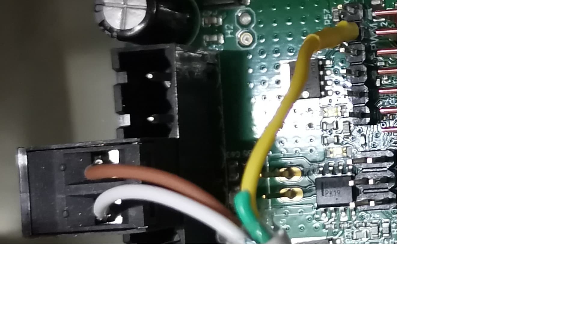
The typical advice on this forum is to reassign FAN_PIN by changing ‘8’ to ‘45’, but you should be able to use any of the three fan pins, and you can reassign them to any of pins 44, 45 or 46. Pins 44, 45, and 46 are all PWM pins. Here is a photo of the pins you would then use for the control logic on your laser: Rambo laser pin.
Note if your laser is controlled using a 3.3v signal, you will have to take steps to bring the voltage down using a voltage divider or some other circuitry between the 5v pin and your laser.
I’m trying to connect my Sculpfun S9 (12v PWM) to a Rambo 1.4 so can’t use pin 45 as that is 5V. Anton has connected his VCC to a PWM pin but I have no idea about the pin numbers. Do I connect the power to fan 0 + and - and leave the VCC cable off like what Robert is saying (I think) or try and do what Anton has done and use the VCC (I’ll need to find a 12V PWM). I’ve read a lot of posts but am totally confused.
Are you sure you need 12V PWM? In this post, Cristian used a 5V pin to drive his Sculpfun S9. A lot of lasers these days can be controlled by a range of PWM voltages. With PWM, the time spent on or off controls the laser, not the voltage.
The second thing you need to figure out is power. The 6A power supply that V1 specifies for the Primo is not enough to run both your laser and your MPCNC. If you have a 6A power supply, you either have to upgrade, or you can use a separate power supply. If you use a separate power supply, you will need to “split” your ground so that both your control board and your extra power supply share a ground connection with the laser.
As for driving your laser with 12V PWM, I think you will have issues. On the Rambo board, the 12V fan connections have their PWM on the ground side rather than the 5V side. This causes issues with most laser control boards and often requires additional DIY circuitry to make it functional.
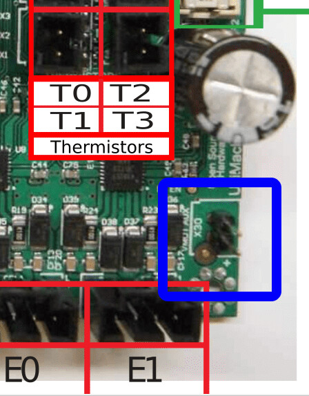
If you elect to drive your laser from the control board, there is a 12V pin pair in the corner of your Rambo board for VCC and ground for your laser. I’ve called them out in the blue square below, or you can wire VCC and ground to the connections where you bring power to the Rambo board.
In summary, the path of least work (assuming 5V PWM will work) is to have a big enough power supply to your Rambo board (I suggest 10A since they are common), use pin 45 for PWM, and use the two pins I called out for your VCC and ground.
Edit: I did a bit of searching. According to the picture in this post, your laser will take 5V PWM input
Thanks a lot for getting back to me. Please forgive my ignorance as I’ve read so much information that it’s messed my thinking up. I’ll give the 5v pwm a shot. Reading another post I put a 10k resistor inline on the PWM cable, shall I remove this or would it not make a difference?
You don’t want the 10K resistor, and on the other posts it is likely it was to be wired between the PWM pin and ground, not inline. The typical use I see for resistors on laser circuits is to pull the PWM pin down to ground before the firmware is fully booted. This avoids a flash of laser light from a floating pin. So, if after you have your laser working you see your laser briefly flash on when you turn on your control board, consider adding a 10K resistor between pin 45 and a ground pin.


