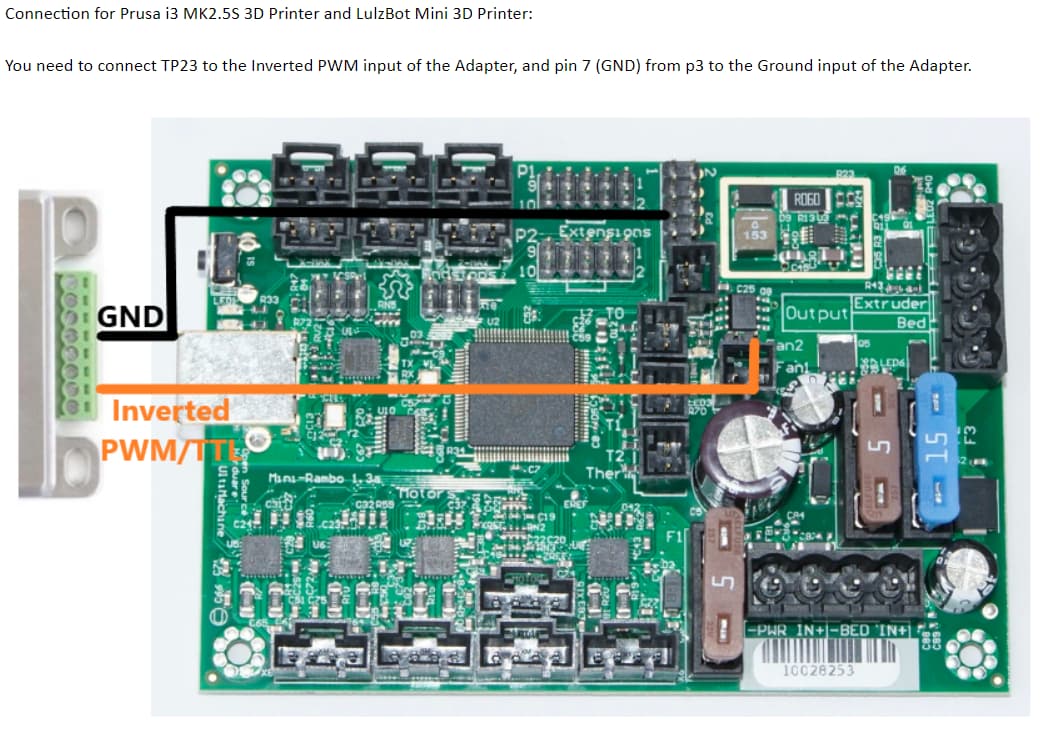
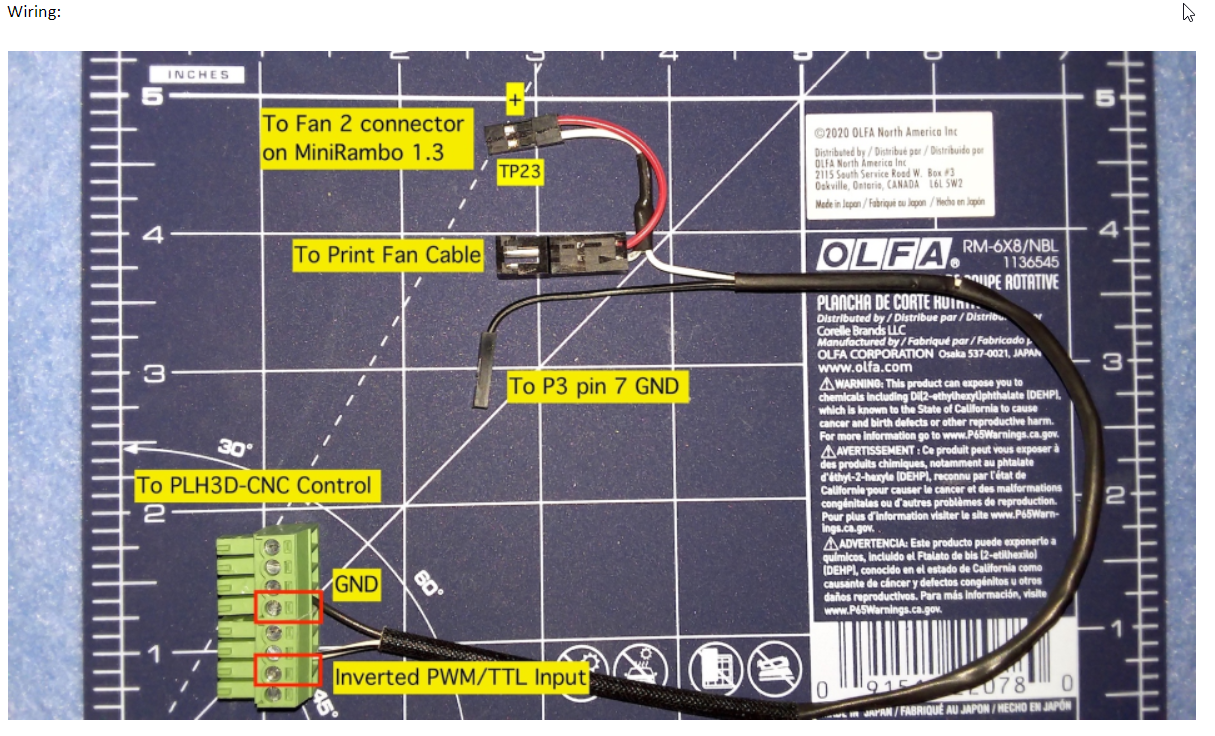
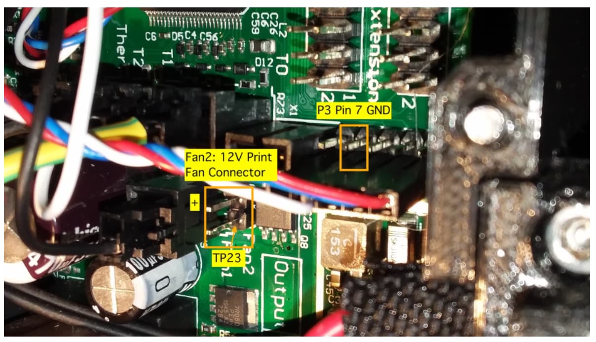
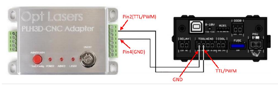
Hi. Help me connect the PLH3D-series laser to the 1.4A RAMBO control. I found a connection to a Mini-Rambo on the Internet. Please look at the photo. The pictures there show 12 volts and I have a 24 volt power supply. Also, the picture shows how to create a cable, I don’t quite understand why and what kind of bifurcation is on the cable?
First off, you have a full-sized Rambo board, not the MiniRambo correct? Currently I don’t believe there are enough pins to run the display and a laser on the MiniRambo. Assuming a full-sized Rambo, the first step will be to upgrade to the latest firmware. Firmware is released here.
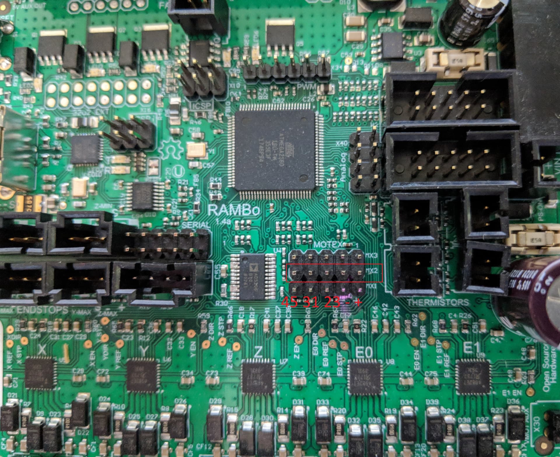
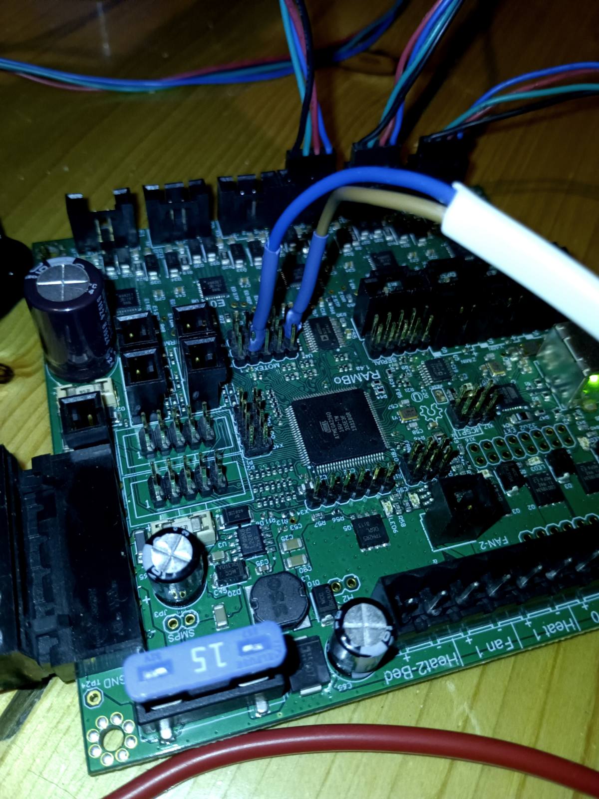
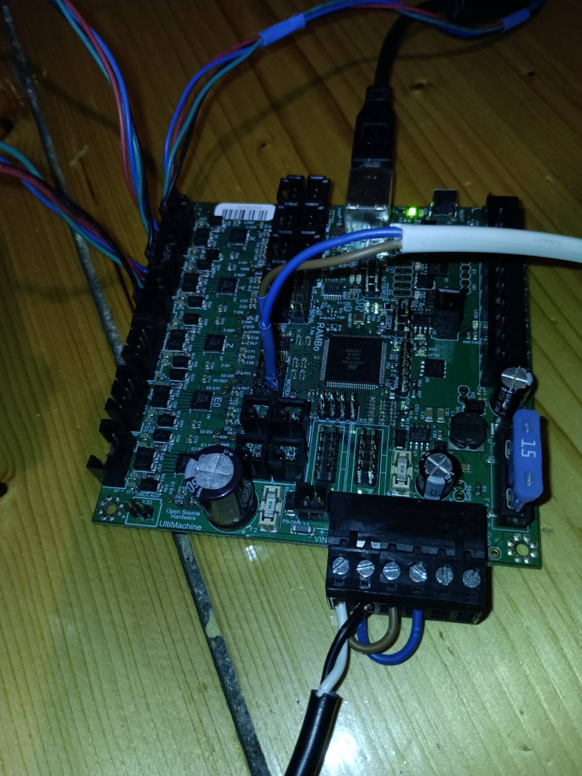
Second is the PWM/TTL hookup. The V1 maintained firmware uses pin 45 for laser PWM. You will find pin 45 is the left-most pin in the middle row:
Power is a little trickier since you need to make sure that your 24V power supply provides enough current for both your Lowrider and your laser. According to the sales page for one of the PLH3D models, the laser will take 24V as input. I would recommend pulling the power from the screw terminals, not from any of the pins on the board.
As long as you pull the power for the control board and the laser from the same power supply, you can get away with just three connections: power, ground, and PWM. If you go with a separate power supply for your laser, then you will also need to tie the grounds of the two power supplies together.
Yes, I have a Rambo 1.4. My laser has its own adapter and a separate power supply. The adapter can be configured for different CNC machines. I set it up for a Mini-Rimbaud (Since there is an explanation of the setup in the manual) and connected the PWM 45 and the grounding as in your photo. The laser began to turn on but there is no power. It glows, but it doesn’t burn out the lines. I did it as in the photo. All via LightBurn.
So how are you driving it from the Lightburn side? I assume you set it up for Marlin? For commands you want:
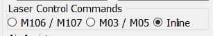
Then you need to put the following at the top of any g-code files you send:
M3 I
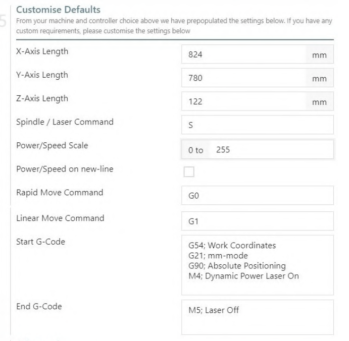
You can put it in Device Settings/GCode/Start Code and it will be added automatically.
As for testing your laser, if you want to be absolutely sure what is going on, you can directly manipulate pin 45 using M42. For example, sending the following should turn your laser on at quarter power:
M42 P45 S64
I tried different codes. I did the initial and final as in the picture. This is a screenshot from the laser manual. It doesn’t work((((
M42 P45 S64 Do you need to enter these codes in the command line? I did it, nothing comes out. I also tried to insert these codes into the start window. Not like((((
You would type them in the console window:
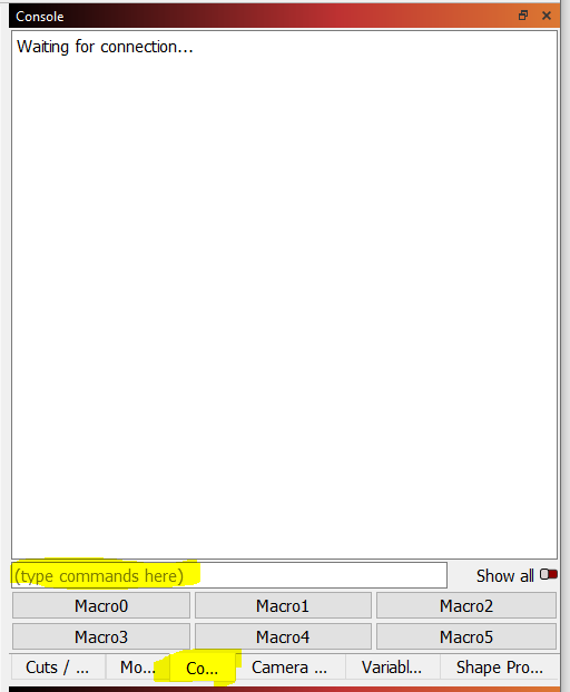
It might be best to start to remove the laser from P45 and then to carefully connect a multimeter to pin 45 and ground. Then you can use M42 and make sure the voltage is varying. Try different S values.
You could also try pin 45 connected to ANAGIN 5V INPUT instead of PWM/TTL, though you really want PWM when you have everything working.
Note there is a safety timeout in Marlin that turns the laser off if the laser is not moving, so, if you use M4 to turn your laser on, then you may only get a brief flash. M42 commands bypass the timeout.
When I press the start button, the laser beam increases. After stopping, it decreases. But nothing burns out ((((
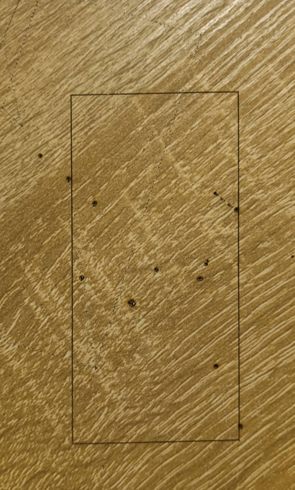
by adjusting the lens and the speed of 500mm. in a minute it turned out to make such a contour. But it doesn’t make sense ((( If the speed is no longer visible lines (((
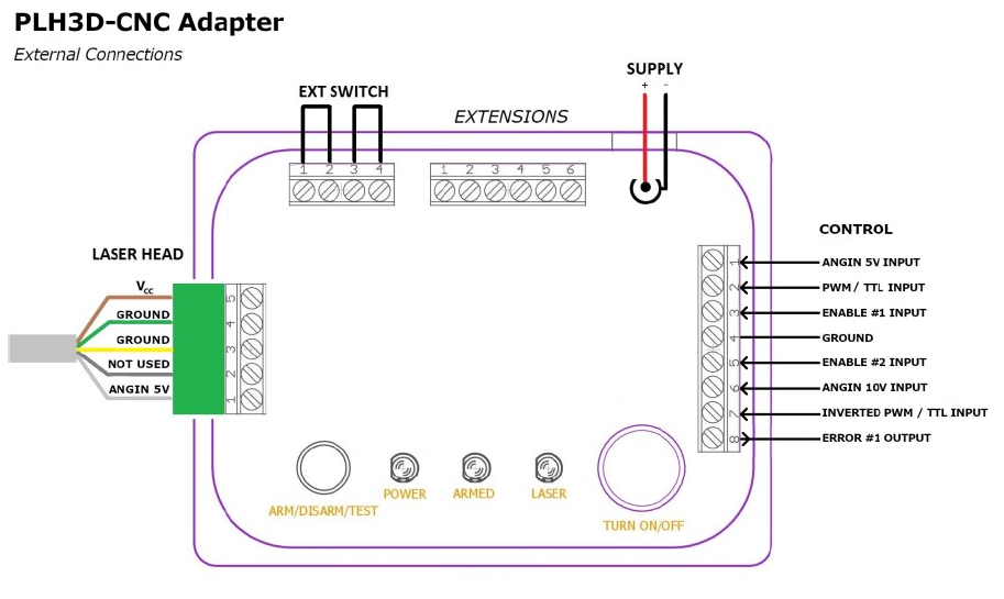
Where on Rimbaud 1.4 can you find a way out for Enable #1 input?
I do not understand your question. What is “Enable #1 Input”? Maybe you could provide pictures of your actual wiring? Did you use a multimeter to test pin 45 with M42 to verify the pin is working as expected? Did you try to connect pin 45 on the Rambo board to ANGIN 5V INPUT?
It turns out very interesting… It turns out that all this time, by mistake, the grounding on the adapter was connected to the input that I asked you “Enable #1 Input". Above I put up a photo where you can see which entrances there are. When I did it right, the laser stopped turning on. With the wrong connection at a slow speed, it turned out to burn out the rectangle. I did your advice. The multimeter with and without commands shows 0.05 V. When I put the PWM 45 on the ANGIN 5V INPUT, the laser did not turn on. In the manual, I found that some controllers with my lasers and the LightBurn program are connected to PWM + grounding +“Enable #1 Input". What should I do?
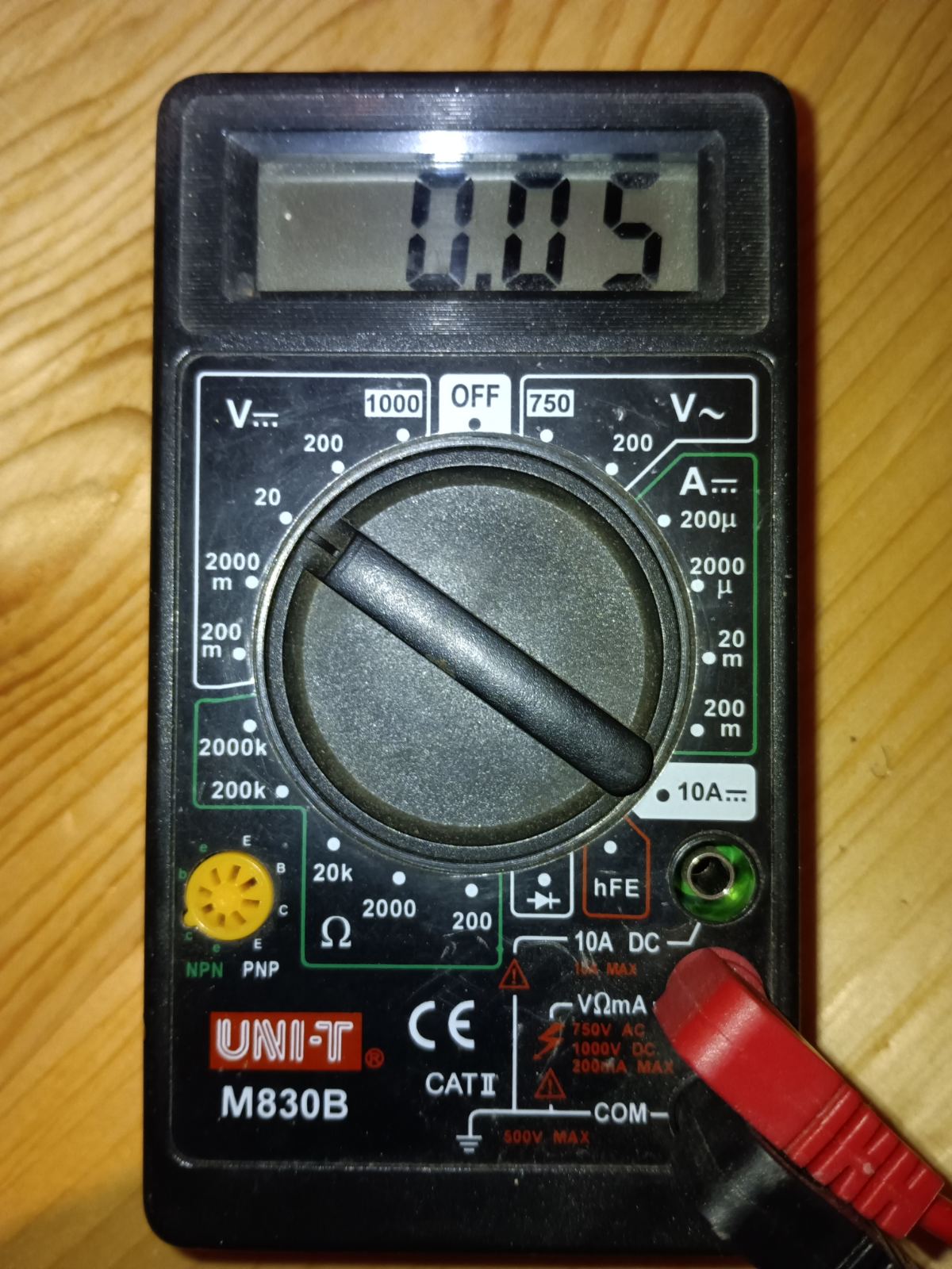
Something is strange here. Without any laser hookup, you should be able to use M42 and vary the voltage seen by pin 45 by changing the S value you send. A value of S128 should produce a voltage on the multimeter around 2.5V. S64 should produce a value around 1.25V. A value of S255 should produce a value near 5.0V. You need to see this working before you can move forward. Are you sure you are running the latest firmware? Older Marlin firmware did not have laser support enabled by default.
As for Enable #1 and #2, I don’t believe they apply for the Rambo board. You may have to contact the technical support for your laser module to figure things out. For most lasers, just connecting pin 45 of the Rambo board to the PWM input of the laser (and sharing ground) is enough to get it working.
You need to assertain where your problem lies. Is it the Rambo or your PLH3D board that is not performing as expected. Have you followed the procedures in the manual to test fire the laser at 100%? (without any connections to your Rambo board).
From what I can see your connections look good with the two enable input pins left floating (do not wire anything to them).
If your test works you could connect the ground signal line (pin 4 of the PLH3D control socket) to any GND on the Rambo (the - connection of any endstop socket for example) and the PWM/TTL input pin (pin 2) to a +5V pin on the Rambo (the +ve pin on any of the endstop sockets for example), this should also then fire the laser at 100%. That would prove your PLH3D is working correctly so you could then concentrate on the Rambo configuration.
1 Like