Killed my SKR Pro board, tried but failed to investigate and fix.
So, using this opportunity to try out an Octopus 1.1.
problem: While doing this brain transplant, I struggled to label and write clearly on the tiny wires, didn’t have enough different colored permanent markers and was worried labels would fall off.
fix: Ended up resorting to binary encoded marks indicating orientation and port number…
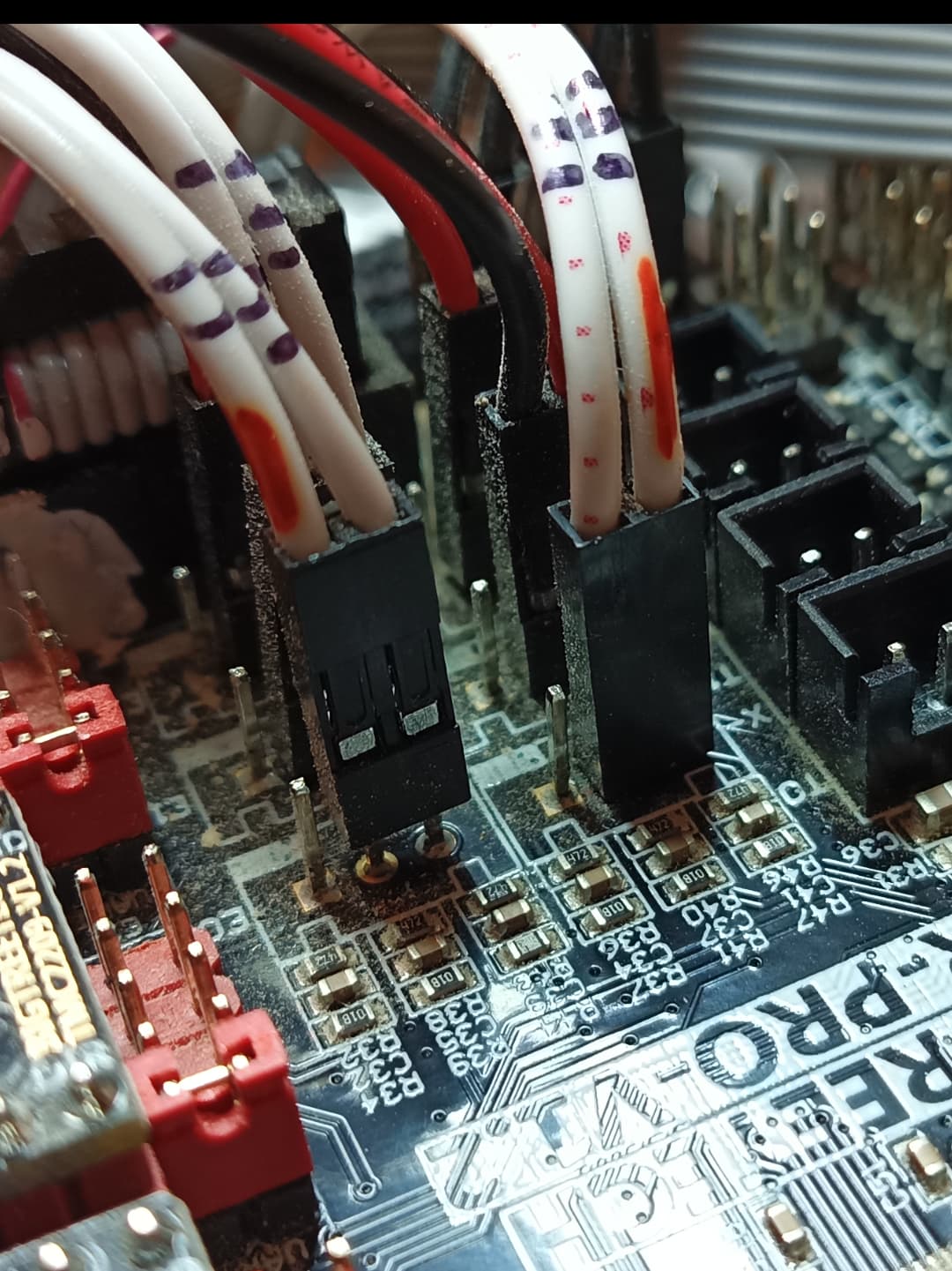
Hope this helps others who, are also incapable of writing clearly on rice and such.