Purple-black-rainbow LR3 🤷‍♂️ , build video @ https://youtu.be/FJ7nYio8oOE

Tell us more about your good idea/cautionary tale!

He plasti-dipped the router. :smiley:

Yep I saw that, was just curious about seeing some pics of the finished project!

Genuine question: why? I have never used plastidip.

Teal Makita was clashing with the core. Issue resolved!

Also… Sharing some details on my LR3 Vac Hose setup. I appreciate the recent topics/posts by misc people going through similar experience.

@Tokoloshe shared a neat parametric Vac Hose Adapter script, can use that script as-is for many scenarios.

Unfortunately the original script was generating a model with a flange…

Made some edits:

  • Added flag for removing flange, enabling gradual width transitions with shorter overall height.
  • Added cut out to fit around lower makita mount. Making install/removal easier.

So, ended up with a mix of reused, remixed and some created parts. Shared files/details at https://github.com/aaronse/v1engineering-mods/…/vac-hose

On reflection, I could have avoided needing an adapter if I didn’t print Doug’s makita-vac-upper…stl as-is, but instead tweaked the design to fit my hose diameter, or used a different 2-1/2" hose. Next time…

Hope that helps. Cheers!

3 Likes

Brought LR3 indoors for more comfortable firmware tinkering.

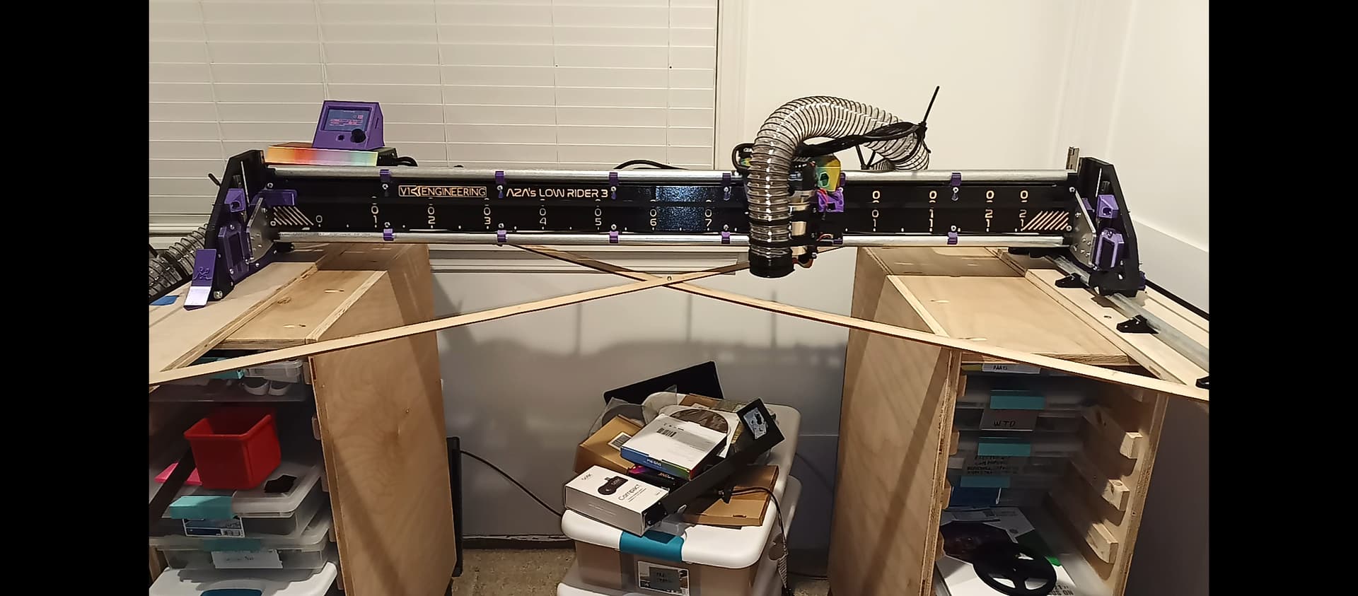
Achieved True square square enough for Y-axis planks just using some skanky scraps cross braced using dimensions derived from fusion-sketch/math.

2 Likes

#lowrider-drag-race

Config: {
Power: 12v,
X-Rapid: 283mm/s = 17000mm/m = 669"/m,
Y-Rapid: 283mm/s = 17000mm/m = 669"/m,
Z-Rapid: 43mm/s = 2600mm/m = 102"/m,
X-Size: 1200mm,
Y-Size: 600mm,
Current: default,
Steppers: V1E,
Leadscrew: V1E // 4 start
}

Not even close to performance of Ryan’s LR3 speed test video. My LR3 is wider, so will never match, still, am wondering whether any build/firmware edits would help?

Didn’t test/measure accuracy, or measure driver temps. Just wanted to speed test before changing to 24V power supply.

; Drag Race
M203 X17000 Y17000 Z2600  ; Set Max speeds
G28 Z                     ; home z
G92 Z80                   ; z max = 80 (instead of 200)
G28 X Y                   ; home xy
M300 S741 P250            ; 3.. 2.. 1..
M300 S0 P750
M300 S741 P270
M300 S0 P750
M300 S1500 P1000
G4 P2500                  ; Wait for 3sec beeps, minus ~0.5sec for command latency
G0 Z0 F2600               ; z min
G0 Z80 F2600              ; z max
G0 X1200 F17000           ; x max
G0 X0 F17000              ; x min
G0 Y600 F17000            ; y max
G0 Y0 F17000              ; y min
G0 X1200 Y600 Z0 F17000   ; xy max, z min
G0 X0 Y0 Z80 F17000       ; xy min, z max

Wirelessly controlled via ESP3D on V1E ESP3D/ESP01s. Created a “Drag Race” macro.

Speed testing to non destructive failure helped identify things to tweak, e.g. vac hose should be strain relief supported, and leadscrews/emt benefit from lube.

4 Likes

That looks pretty fast!

That is pretty close. You can add current to the drivers, and tweak the accelerations. But really…it is faster than you will ever need it to be already. I need to try that test again on video with the 24V.

2 Likes

LR3 docs contain a schematic with dimensions. While designing the bench, found it helpful to import that image into Fusion 360, and calibrate the size. This helped me to measure good enough dimensions between things not already called out by the schematic. For example, I wanted to know how close the router bit will get to table edge given where Y-Axis blocks are located.

Sketching the table dimensions also helped figure out how long to make cross braces to help square the rails.

2 Likes

On the right side it looks like the router can cut through the rail blocks, is that right? :smiley:

LOL, yeah right side of the diagram is inaccurate. Reason… My table size differs from the LR3 docs schematic, and I didn’t bother to crop and copy-paste the right side to be accurate for my table. You probably guessed already and are going through something similar? Was focused on trying to understand the left side details enough to figure out where I wanted everything.

1 Like

Yeah, I know exactly how you feel. :smiley: My problem is I want to make a vacuum table again (obviously) and this time bought plywood instead of MDF because it is airtight from the get got. Because I also want to build a torsion box AND have the pipes inside of it, it requires a bit of planning and thinking where the holes have to be in the box… :smiley:

This is what my plan looks like. Don’t worry, I understand it… :smiley:

3 Likes

Nice! Look forward to seeing your LR3 vacuum table setup. Learned a bunch from your topic, had no idea that MDF could be used as an air filter.

Your MPCNC’s Vacuum table topic, and my want to utilize space inspired me to keep the front open. Open front leaves me with options for storage (see pic), or drop table scenarios or partial vacuum in the future. The middle to rear half is solidly closed, glued and screwed like you’d expect for a torsion box. The front half is different though… Although the ribs in-between the plastic storage containers are also glued and screwed, there’s no front rail. Bottom ply skin is not glued yet, so this setup isn’t a proper torsion box imo, am keeping an eye on deflection will tweak as needed.

2 Likes

Killed my SKR Pro board, tried but failed to investigate and fix.

So, using this opportunity to try out an Octopus 1.1.

problem: While doing this brain transplant, I struggled to label and write clearly on the tiny wires, didn’t have enough different colored permanent markers and was worried labels would fall off.
fix: Ended up resorting to binary encoded marks indicating orientation and port number…

Hope this helps others who, are also incapable of writing clearly on rice and such.

2 Likes

I used to use white out for that. I didn’t use binary as much as just roman numerals. I would mark both ends so I could tell is a specific SATA was connected to a specific drive.

3 Likes

One trick for writing tiny labels on wires is to write them on light-colored heat shrink BEFORE shrinking, then slip it on near the connectors, then shrink so it won’t slide around. You could put your name on a rice grain easily this way!

7 Likes

Cool

Still futzing with Fusion 360 to create flat packable stackable mountable (or stand-alone) modular MPMC Case (Minimally Printed, Mostly CNC’d).

PCB mounts slide into the corners pieces that also grip the CNC’d panels.

Almost done… Still not clear if this is a good idea or not, will try it and see…

4 Likes

Ok that’s cool looking. I very much dislike my wiring for my primo and really need to take the time to model up something better for the board. I like how you put In acrylic to be able to see it. Might have to do something like that. Sometimes it is nice to look down and see the light for the endstops and know everything is working as it should

2 Likes

OMG I love it!!!

2 Likes