Not at all. It provides a range of values that are an excellent starting point.
Keep in mind a few things.
Firstly, every LR build is different, and has different capabilities and rigidity, depending on materials used during the build, on design choices made by the builder, and on the quality of the build. Your machine will have different capabilities than mine, and different than a Maslow or any other lightweight CNC,
Secondly, every piece of cutting stock will vary in density, grain, hardness, etc. One type (or even one sheet) of plywood will vary from another in cutting characteristics.
Thirdly, different end mills will behave differently under different conditions,
Use the ranges given in the article as a starting point. Choose the lower end of the range if you think that your machine is a bit less rigid (wider gantry, etc) or start in the middle of the range if you’re confident of the machine’s capabilities.
Do some test cuts in the stock you plan to use. Listen to the router/spindle for signs of straining or bogging down. Look at the debris created. Is it sawdust or actual chips? Are you skipping steps?
You will need to learn the capabilities of your machine, and the different materials that you are cutting, and adapt accordingly. Nobody can give you a magic number that will work perfectly in all situations. But we can give you information as to where and how to start (see above)
That’s an indication your spindle speed is too high and building up too much heat, it’s not a case of faster is better- heat is carried away by the chips so the tool need to take decent ‘bites’ out the material to be efficient.
These are good points, I’ll think on it more and try to apply your advice as I gain experience with various materials and bits. Thanks for taking the time to explain.
Or feed too low, as indicated above. I upped the feed rate to 120%, and things smoothed right out.
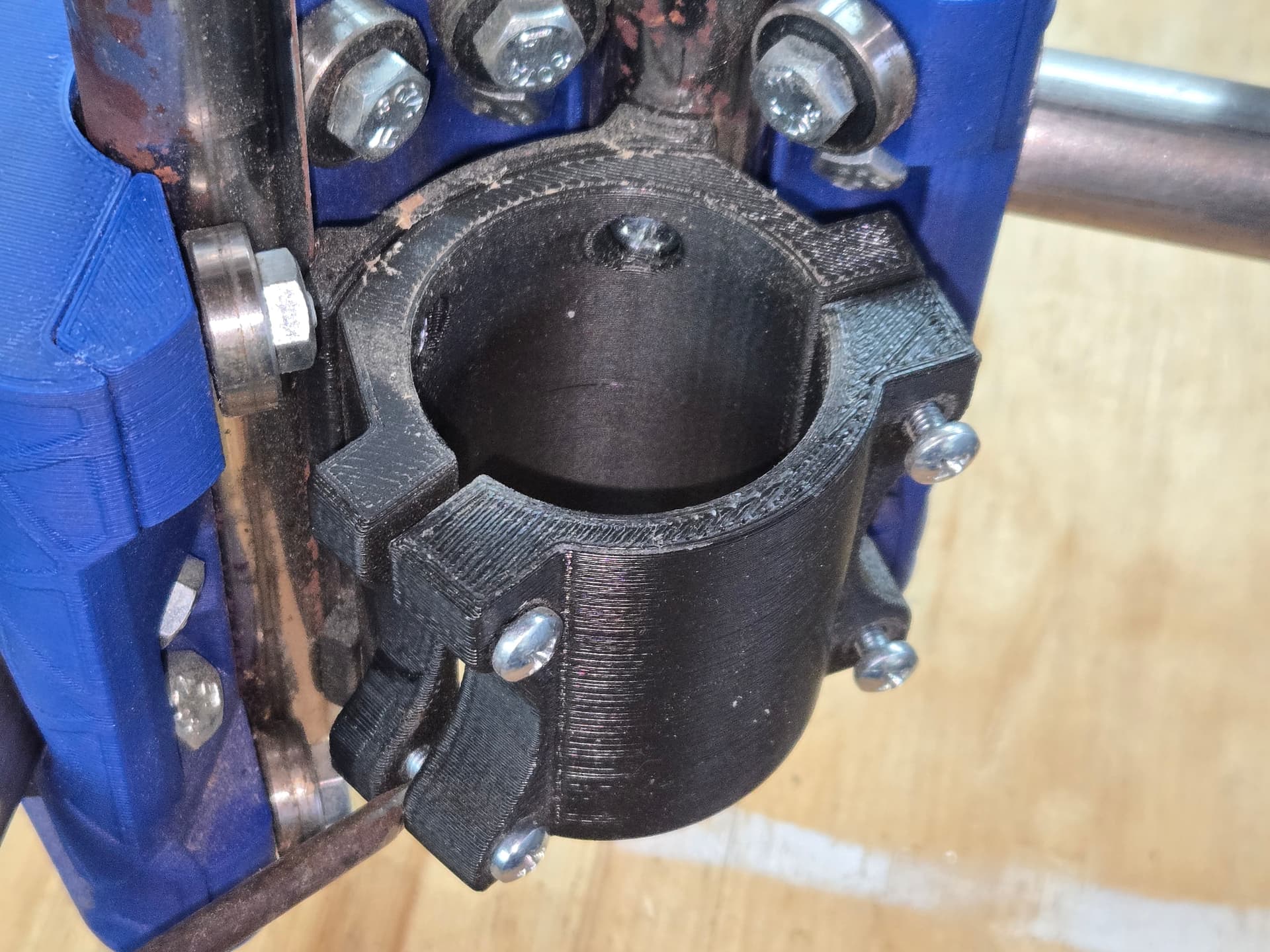
So I was running some tests this evening, and noticed that something looked funky on the cuts.
Upon closer inspection, I realized that my spindle motor was slipping in the mount! I tried tightening it up just a little, but one screw (bottom left) wasn’t getting snug. I saw immediately that the rear side mounting ear was cracked. I superglued it back in place, but I have no real confidence that it will hold. I figured I’d just print a new mount, but I can’t seem to identify the right parts… I found this mount, which seems to be correct, based on the name, but it looks a little different than my current one.
The current mount has a back plate that the mount…mounts to.
Is this the right model? I just want to be sure, since it’s likely to be a fairly long print.
Cool. I hope it works, because I’m printing one now…
The one on Printables looks a bit different than yours and mine. Maybe it’s just been updated. We’ll find out shortly.
Progress report:
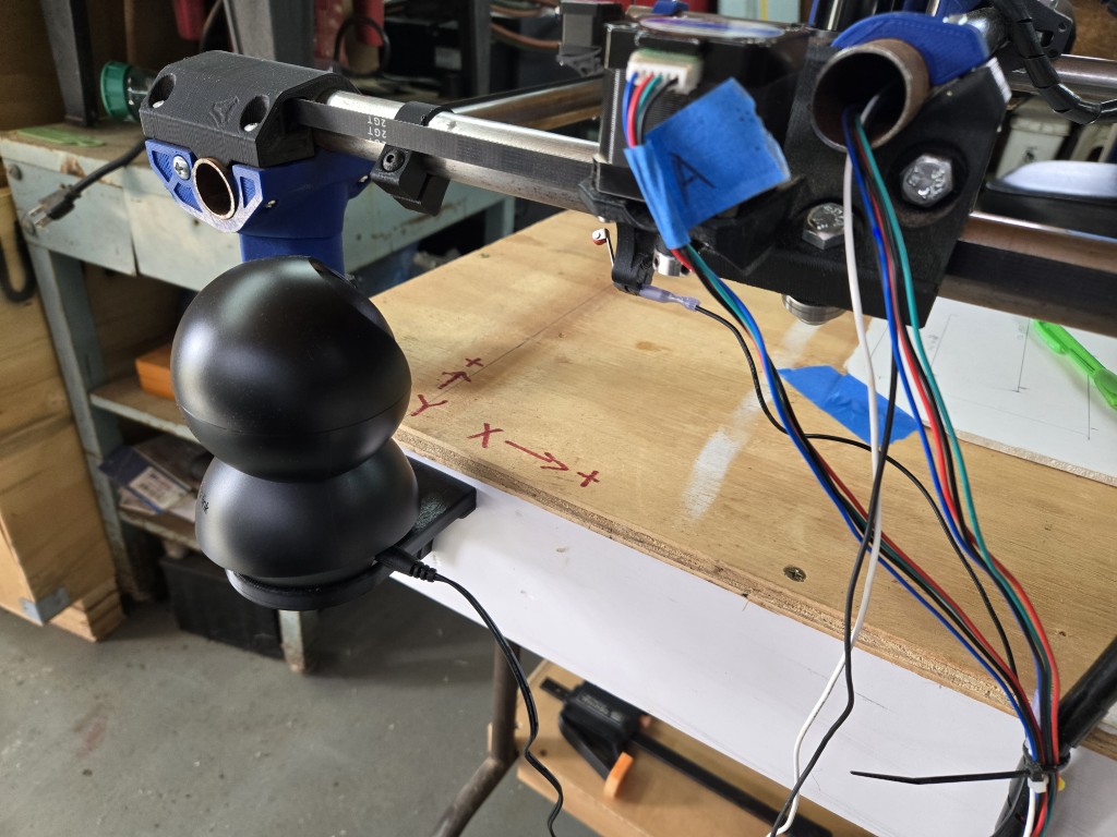
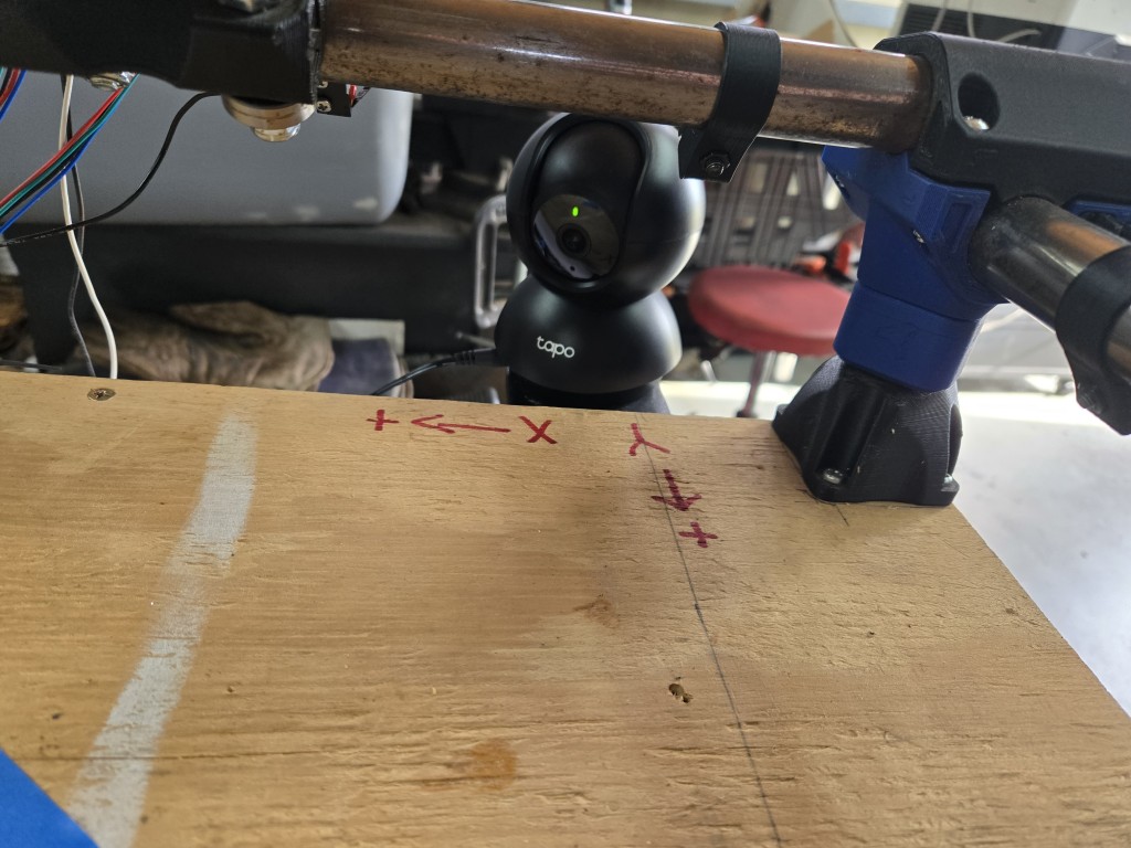
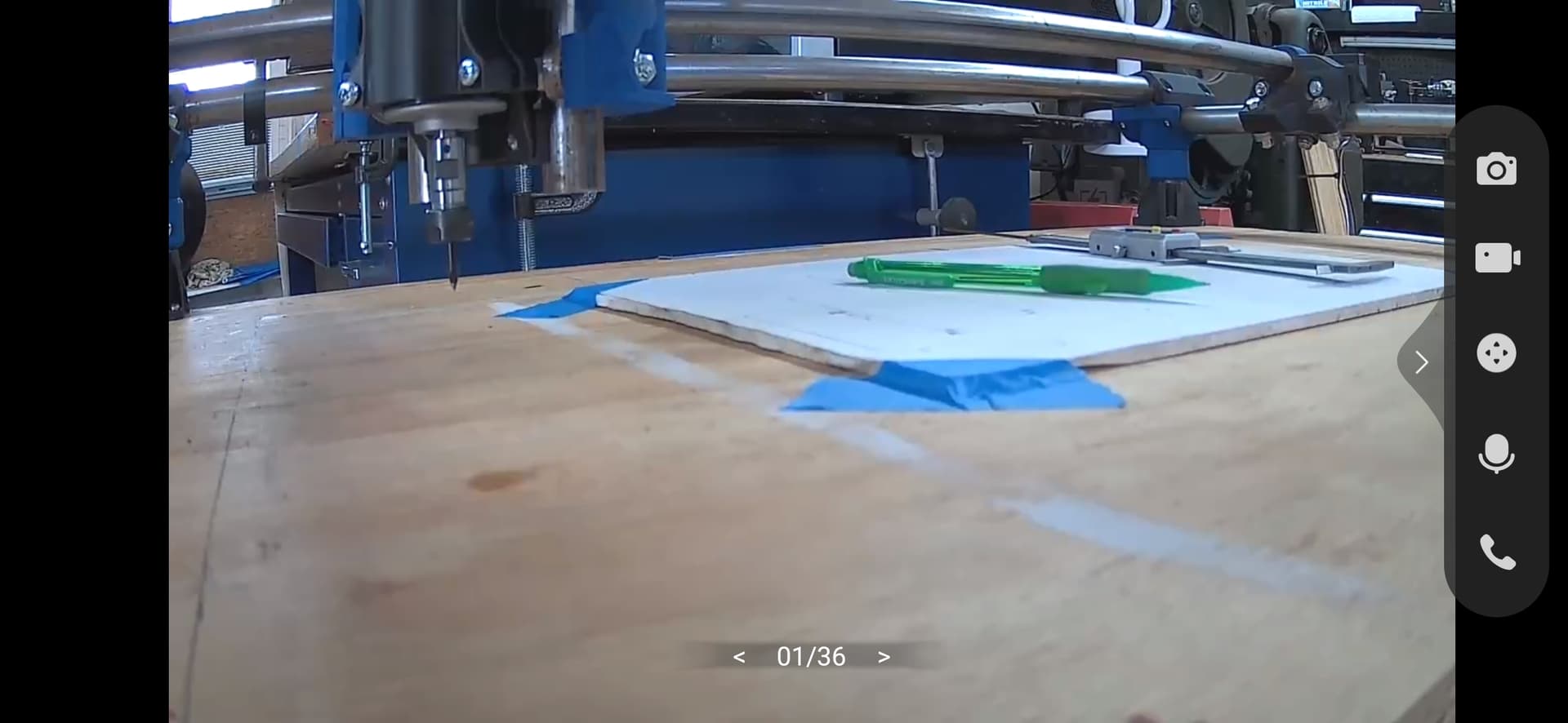
I’ve modeled and 3D printed a mount, so I can install a small IP camera to monitor things while I’m not there in the shop. This Tapo C201 is a pretty good camera (so far) for only $19 shipped.
I won’t use this for regular jobs or anything, but it will be nice to watch it work from my desk, if it’s a longer cut job.
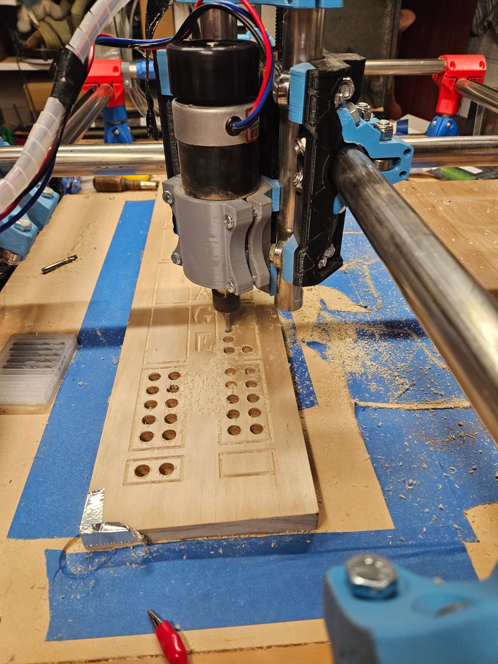
In other news, I’m trying to figure out why my holes are cutting undersized.
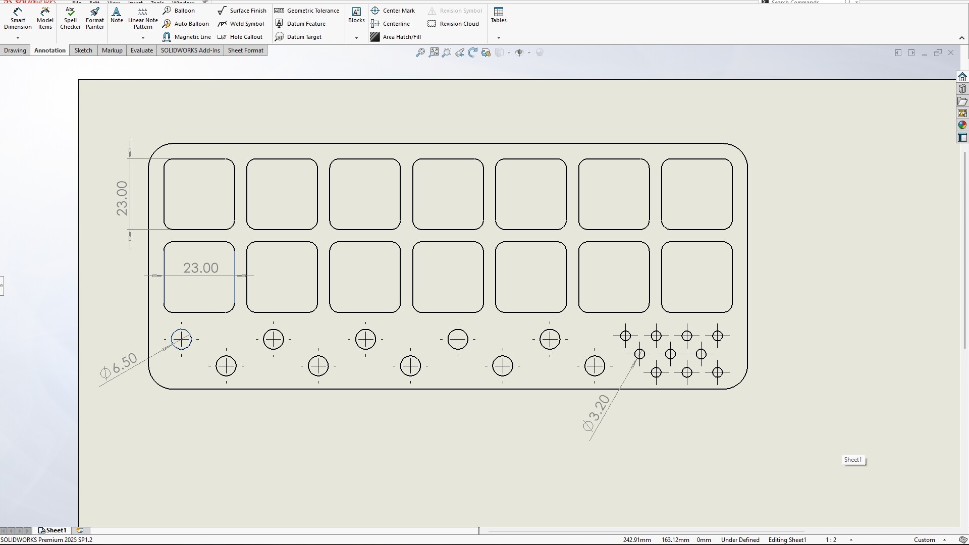
In that test job I was doing earlier, I had a row of holes that intended to hold 1/4” router bits. Those are 6.35mm shafts, so I modeled the holes as 6.5mm dia. to allow a little clearance.
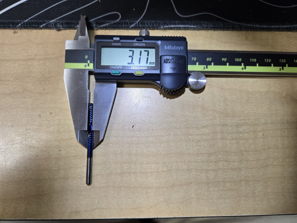
There are a 2nd set of smaller holes, meant for 1/8” bits. Those are modeled at 3.2mm, so basically a drill with a little wiggle.
My bit is a 1/8” (3.175mm) spiral O-flute upcut. I thought the tool was undersized, but it checks out.
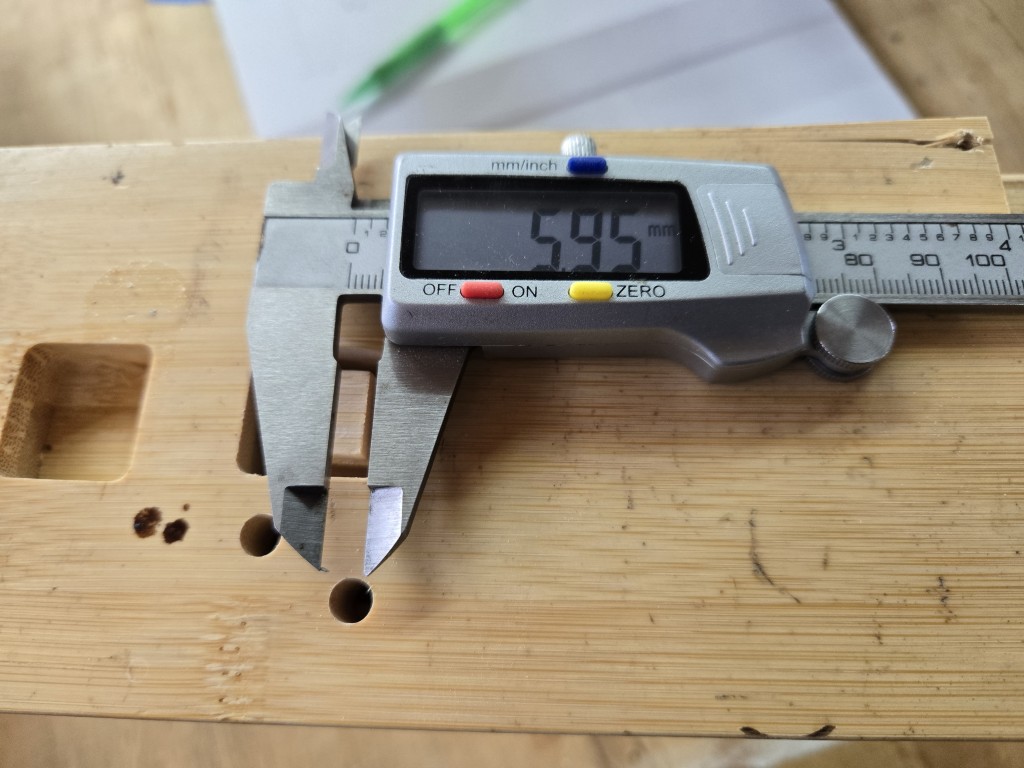
When I run the job, the holes are cut too small, by quite a bit. (see image)
The larger holes are running about 5.9-6.0mm (I measured a couple of them, several times), and the small holes (not shown) are just under 3.1mm. Neither will accept the bits they are designed to hold.
I thought maybe my machine wasn’t calibrated, so I ran the axis movement tuner within gSender. It shows my X-axis is spot-on, and my Y-axis sometimes measures a hair long, sometimes a little short.
I think it was me not being able to get my pencil lined up on the pen tip perfectly.
Anyway, all that was to say that I can’t figure out why a hole drawn at 6.5mm is being cut ~6mm.
I thought I had the tool size set wrong in EstlCAM, but it’s on 3.175mm.
What else should I check?
EDIT to add: This is the layout in the design software, with the desired dimensions.
Is there any way to accurately measure an object in EstlCAM? It all looks right, but I can’t tell if it’s 10% off size or night.
I’m also noticing that the square 23mm x 23mm pockets are cutting at 22.85mm, if that helps anyone with the troubleshooting. I swear it acts like the tool is undersized, right?
Do not do this please! Something goes wrong that thing can be on fire before you even know it in the camera and way too late for you to get to it to stop it.
That’s what insurance is for!
Seriously, though, I run long laser engraving/cutting jobs and long 3D printing jobs remotely fairly often. There is absolutely an increased measure of risk involved.
However, the likelihood of something bad happening is less than the 100% chance of me suffering back and foot injury if I have to stay there and watch it cut a 2-hour project.
Thanks for the warning!
Believe me, watching your home burn to the ground is pretty much the opposite of fun. Knowing that you caused it because of laziness, ignorance or just being pig headed is even less fun.
But hey, you do you. Just make sure everyone else is safely out of the house before you let the machine run free to start the fire.
Just to soothe everyone’s alarm bells, this machine sits in the middle of a concrete floor. It could probably burn to the ground without doing much more than sooting up my shop.
I’m very focused on safety. I don’t run it in the position you see in the photos. That’s just for setup and movement testing.
It’s also in a detached building that’s not close enough to my home to spread.
I really didn’t expect to start a great debate by posting a simple QoL update. Yikes. lol
Can we please move on from the potential fire risk and address the other questions?
I would really like to figure out why the machine is not usable right now, since I have a little project coming up soon that I’d like to make with it if possible.
0.15mm clearance is not very much. About the thickness of a post it note. In Wood products, that is never going to be enough. Plastic maybe, metal probably.
Are you using a full depth finishing pass, if not you 100% have to if you are trying to hold tolerances like that. In the case of a hole I would also do that finishing pass slower than normal.
Ok, I didn’t realize things were that ‘loose’ on the wood side of the house. lol I’ll adjust the design.
No, but I will! Thanks for the tips.
So I guess the bottom line is that this machine isn’t going to be all that accurate, and I need to allow for flex in my designs? I can work with that, I think.