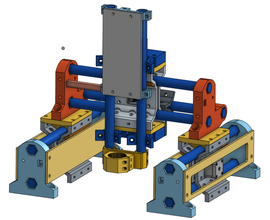
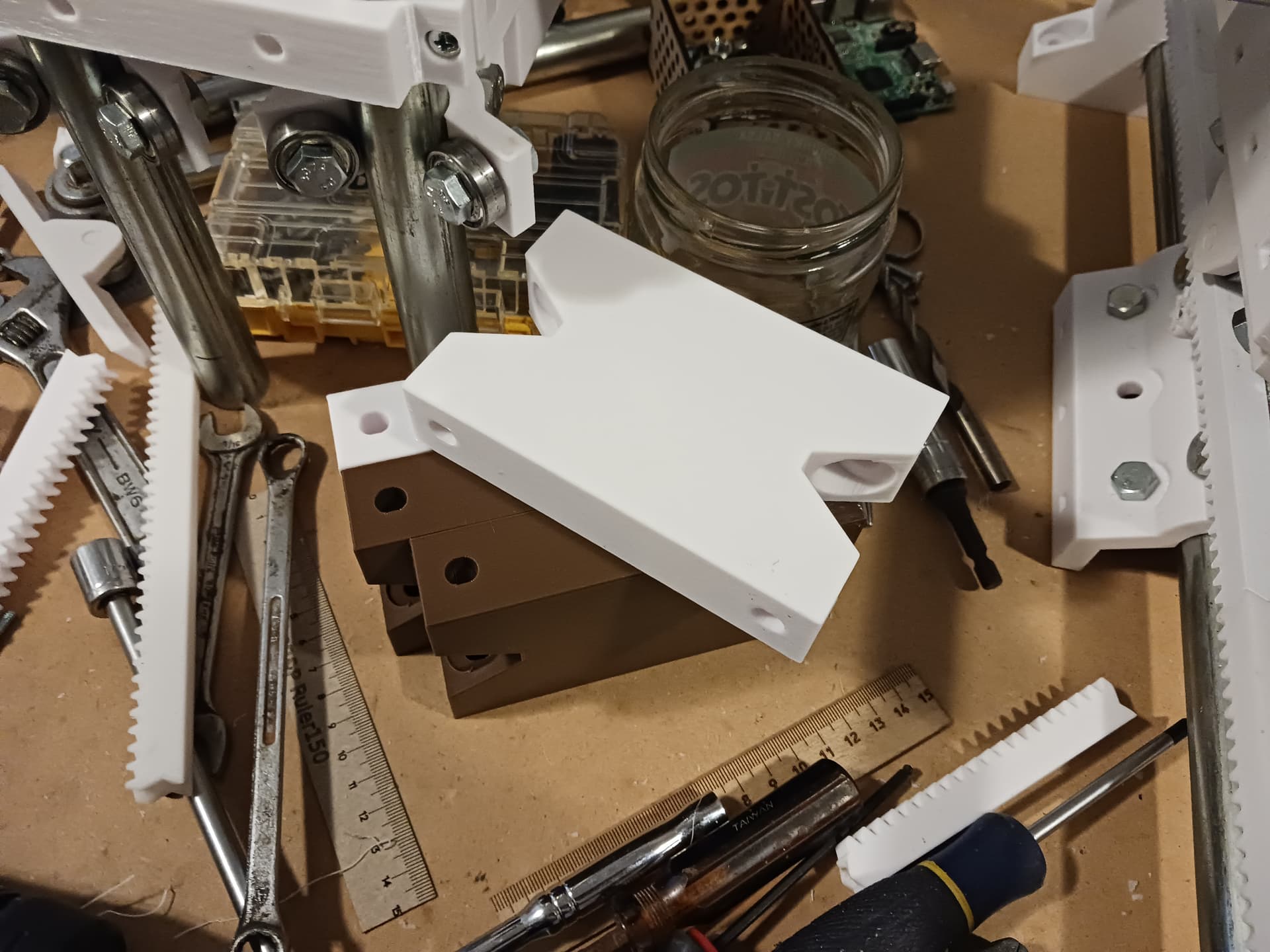
The MPR&P page on Printables has been updated again. I really think this is getting close to as far as I can take it. I’m fit-checking parts and updating my prototype MPR&P to incorporate the latest changes.
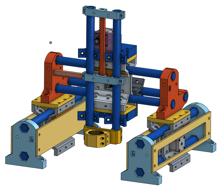
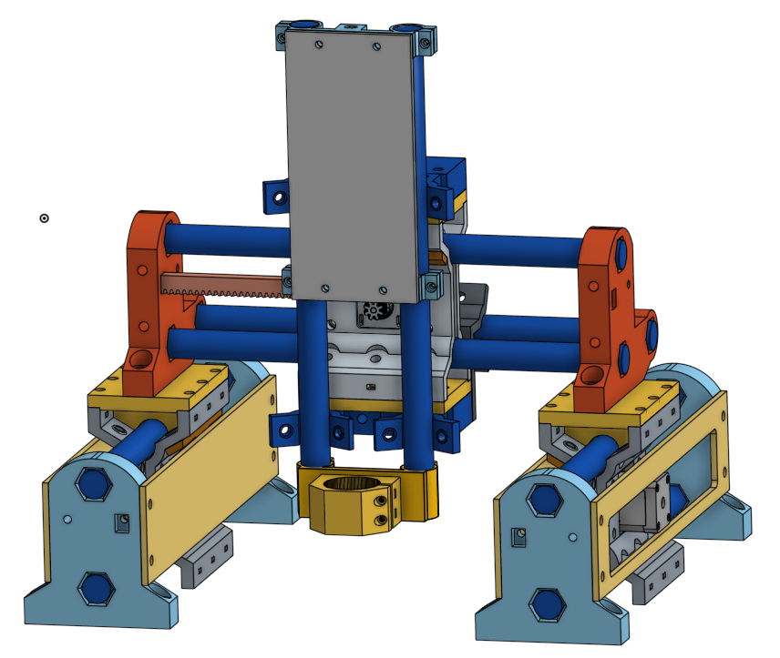
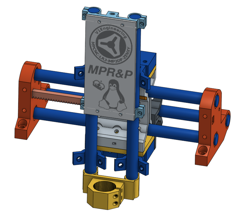
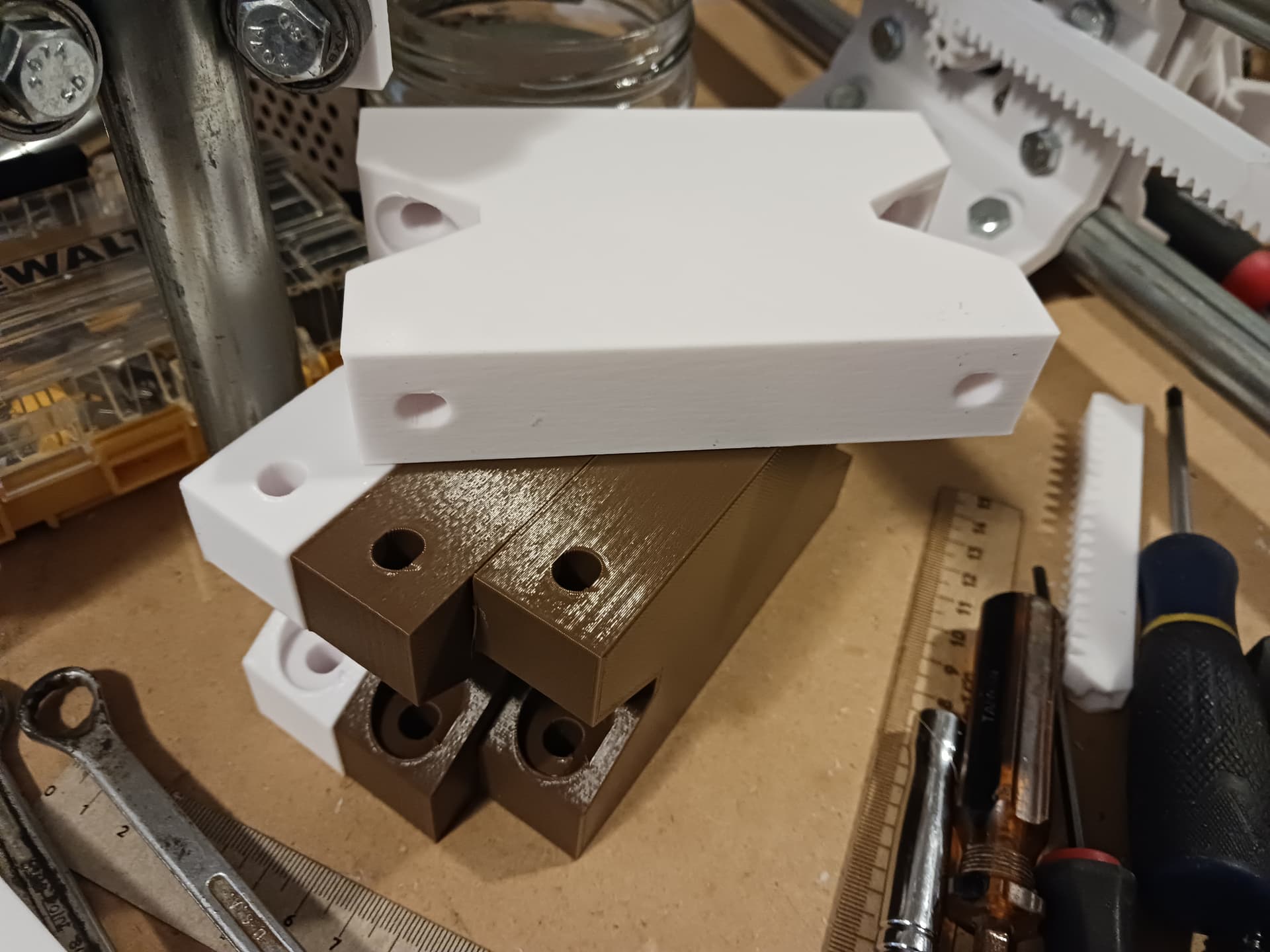
Added screw-clamp rack supports (no more snap-on parts except light tool mounts) on the Z-axis and a front cover-plate that makes a handy place to doodle.
I’m reviewing the latest Printables release, and will circle back to my test build.
I did make a remix to provide a minimalist mount for jackpot- which is little more than chopping the rack mount of the original design apart and then adding back holes for M3 screws in the Jackpot hole spacing… Will try that to see if it lets me wire up the machine I have.
If that works, I will make another one with the Airdale spacing and will install them flipped and interleaved so that the jackpot will be on one side of an extended Y rail and the Airdale will be on the opposite side, back-to-back.
If I understand it properly, nowadays, .3mf model files are preferrable to STLs. And since PrusaSlicer doesn’t object to loading them, and in fact saved its project files in that format, I added the new parts as .3mf files… and left a few of the unique STLs in place. Hopefully, that’s the way I’ll proceed in the future.
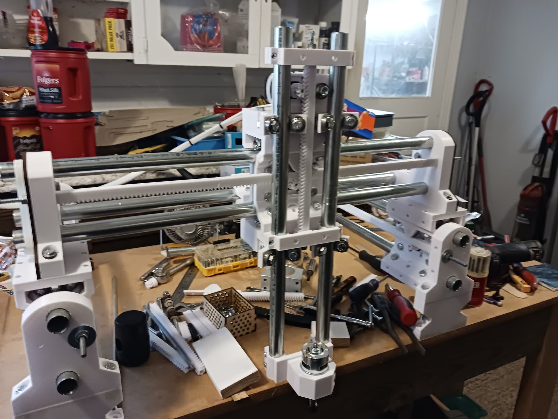
I’ve already changed the Y-rail assemblies over to the new parts… and am fixin’ to tear down the gantry and switch it over as well. At that point, my prototype machine should be up to date.
I’ve not addressed anything related to enclosing my electronics or managing the wiring. I figure that will be the biggest variable between different builds and hoping that I’ll be able to pick up a few pointers from you and any others builders as you present them to the world. I’m anxious to see what all you come up with…
They’re a more open standard - seems you’re also the type to care about that sort of thing It also allows you to save multiple “parts” in one “tray”/machine bed which I figure is the real kicker behind PrusaSlicer using them. You can also save colour data in them, though I still don’t see why anyone should care! (multicolour printing is and maybe always will be a gimmick in my book)
While I’m here. I’ve been following this thread with interest, mostly wondering if I’ll one day have the engineering chops to design something even a tenth as cool… I also might build one for a very silly project I’ve had knocking around in my brain for a while. Need to get my printer back in order first, and I’ve been spending all my troubleshooting time on the LR4…
Thank you for the .3mf info and the kind words. I suspect that you can also tell that multi-color printing is important to me since I do everything in white Sunlu PLA/PLA+.
And get that printer and LR4 going… you’re missing out on all the fun!
I also had “trademark white” for a while when I ordered an unreasonable amount of Prusament to get the per-spool shipping cost to somewhere reasonable. These days I just go for whatever’s cheapest, which seems to invariably be black.
Oh I know! The printer probably needs very little tinkering to get back to full chooch, it does have Prusa written on it, after all. I did also have a little, er, incident, and bought a Prusa Mini which should get here soon. So that’ll at least let me make bits for the LR if I still can’t motivate myself to fiddle with the venerable one. As for the LR, it’s all down to my impressively poor carpentry, I suspect…
Looks like the carriages are considerably improved with the new parts, so I’m going to print a fresh set of those. I’ll need to go looking for hardware again, are these M5s? What length screws did you use? Cap head?
I’m not sure I need the side plates, but if I do the end supports are easy to print, so I’m not going to do those. Really wanting to get the machine running.
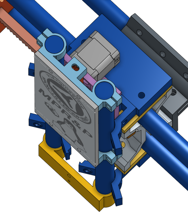
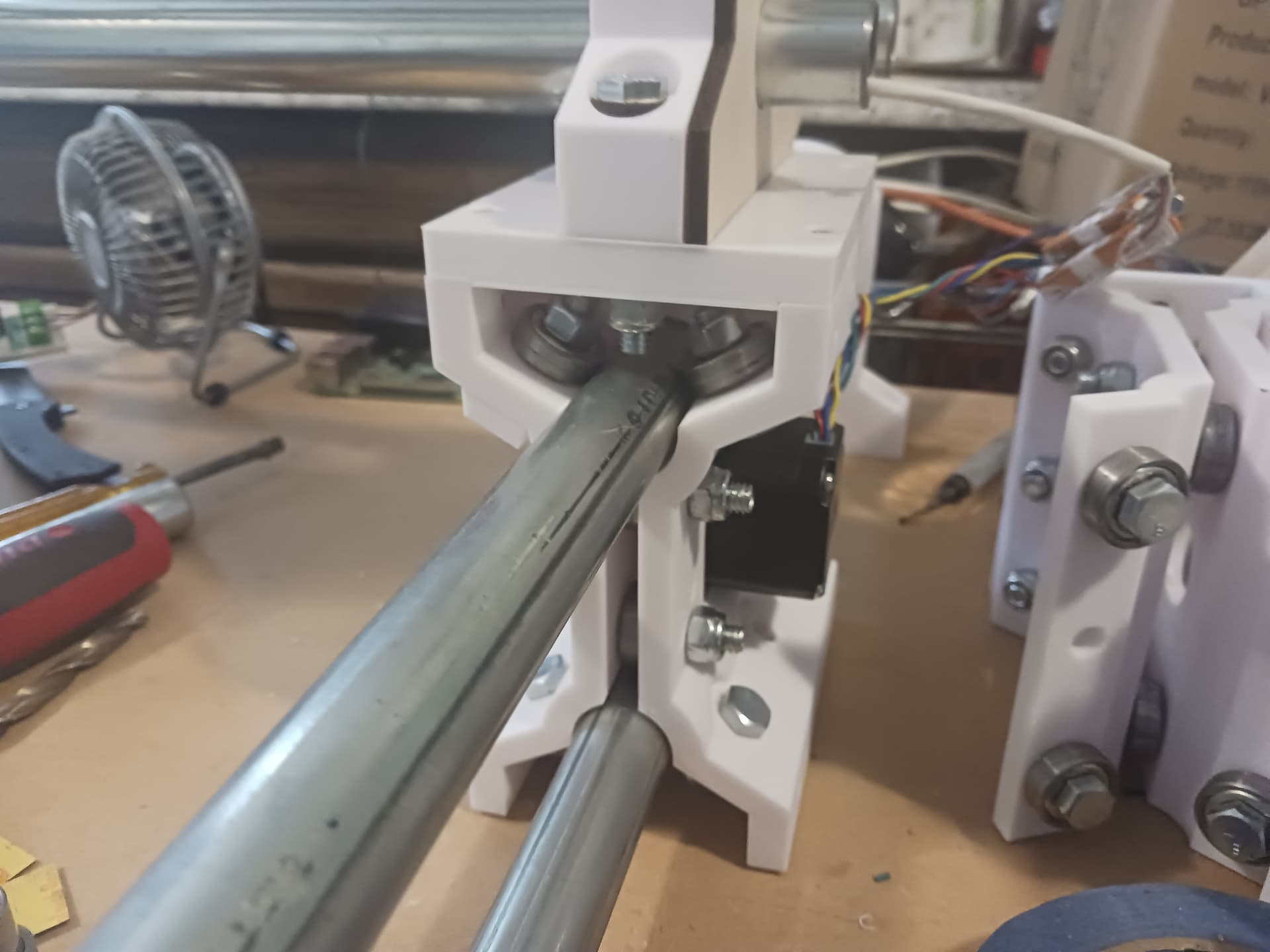
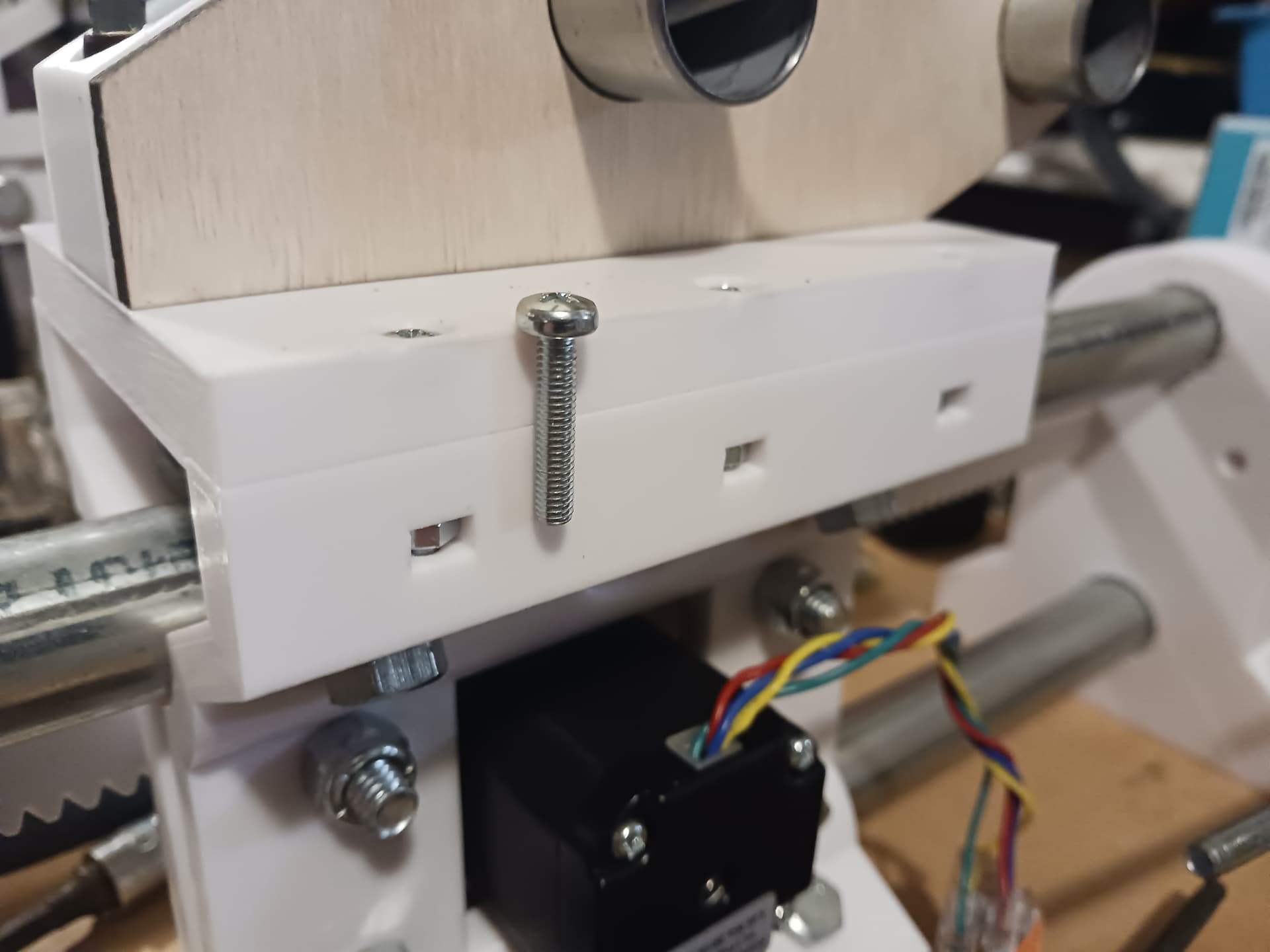
I assume you are talking about the carriage cap_plates and the six screws fastening them to the carriage halves? They are M4 x 20mm Phillips pan head machine screws… the nuts of course are fitted into the recesses in each carriage half. There is a thin single-layer support in the counter-bores to allow for cleaner counter-bore… very easy to cut/drill out.
I’m a bit bummed that I don’t have more Z travel. I’ve thought about printing 2" thick spacers sitting between these cap plates and gantry ends to elevate the entire gantry. Or, maybe better, putting the entire machine on a frame or some kind, allowing for a drop middle… possibly like this or even simple 2 x 4 lengths under each Y-rail assembly
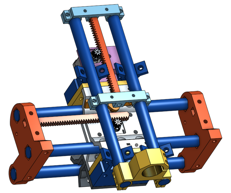
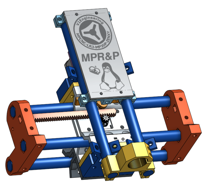
At any rate, I’m probably also gonna lengthen the Z-conduit rails and maybe put another 20-tooth rack segment in the Z-axis R&P to try to maximize the travel I should already have… my first 40-tooth SWAG at it doesn’t allow for as much travel as I thought I would have. That’s a pretty simple and easy first step.
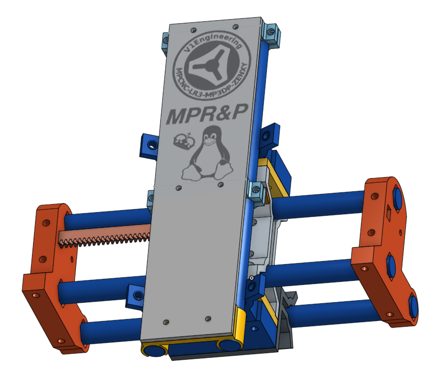
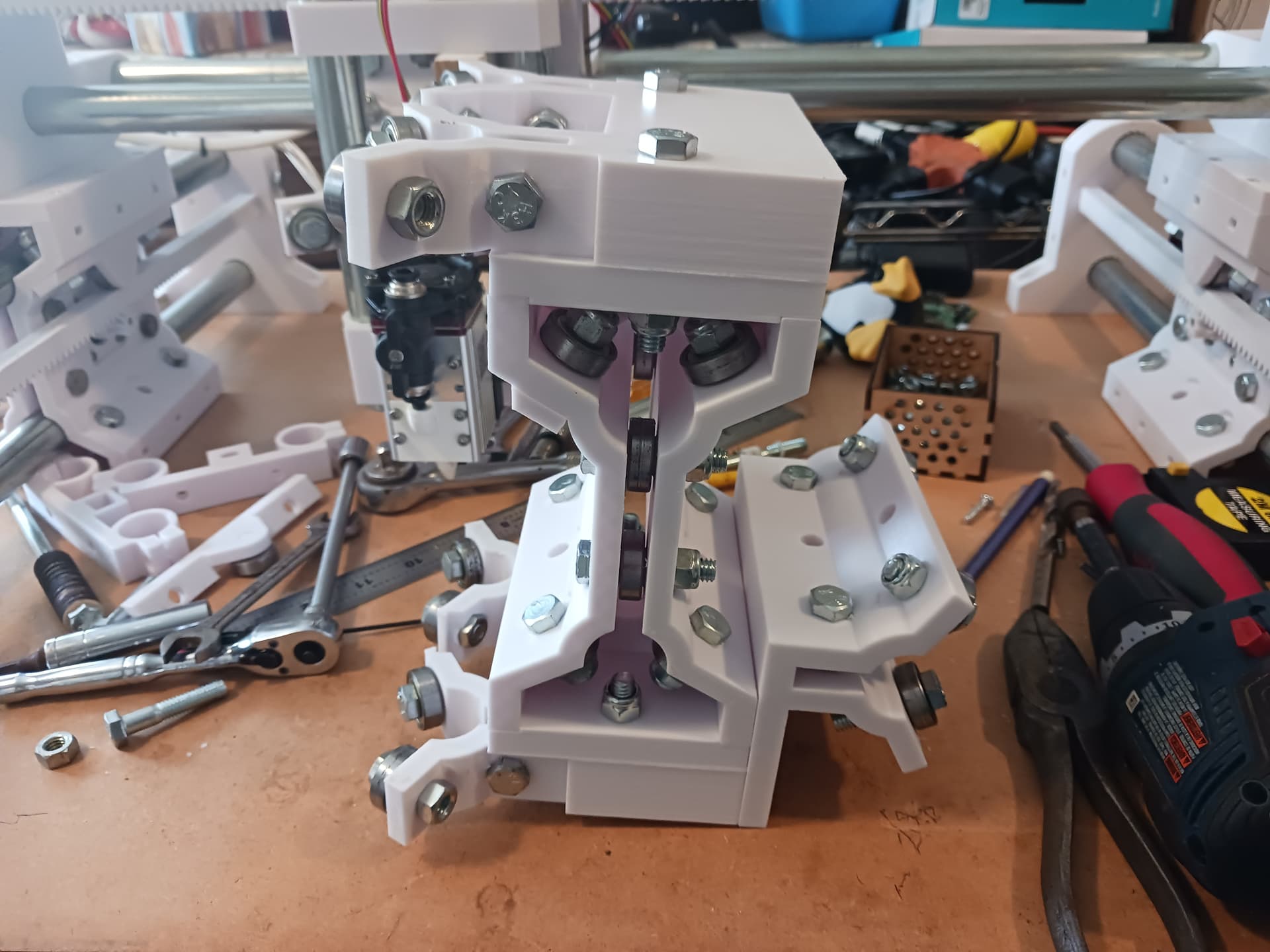
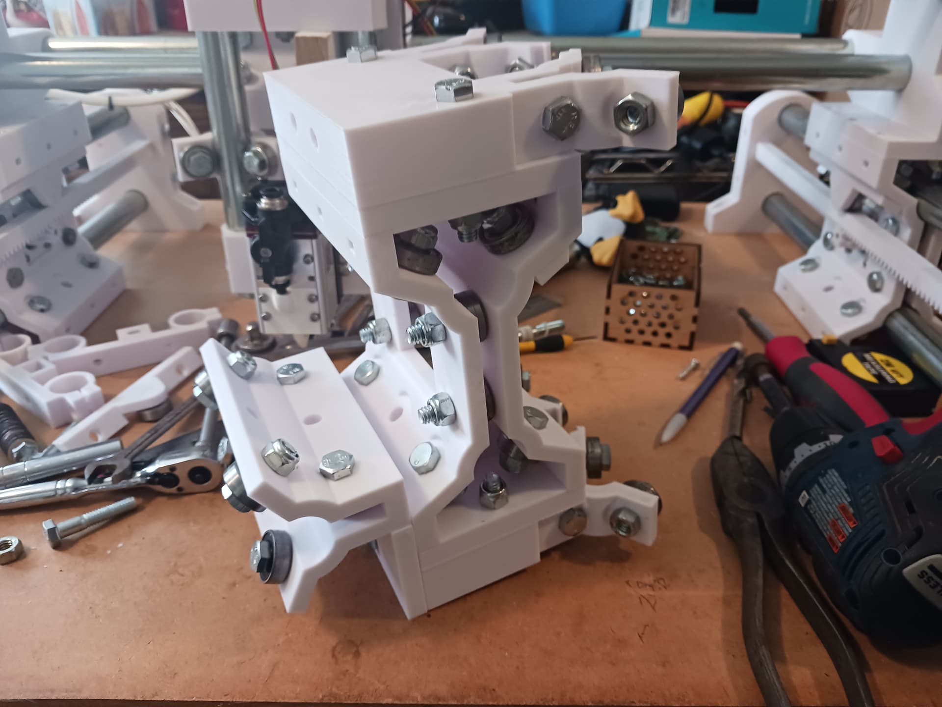
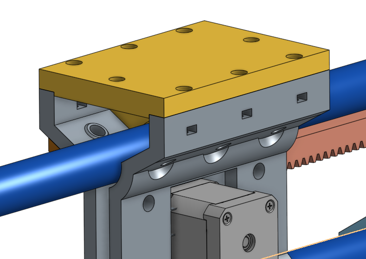
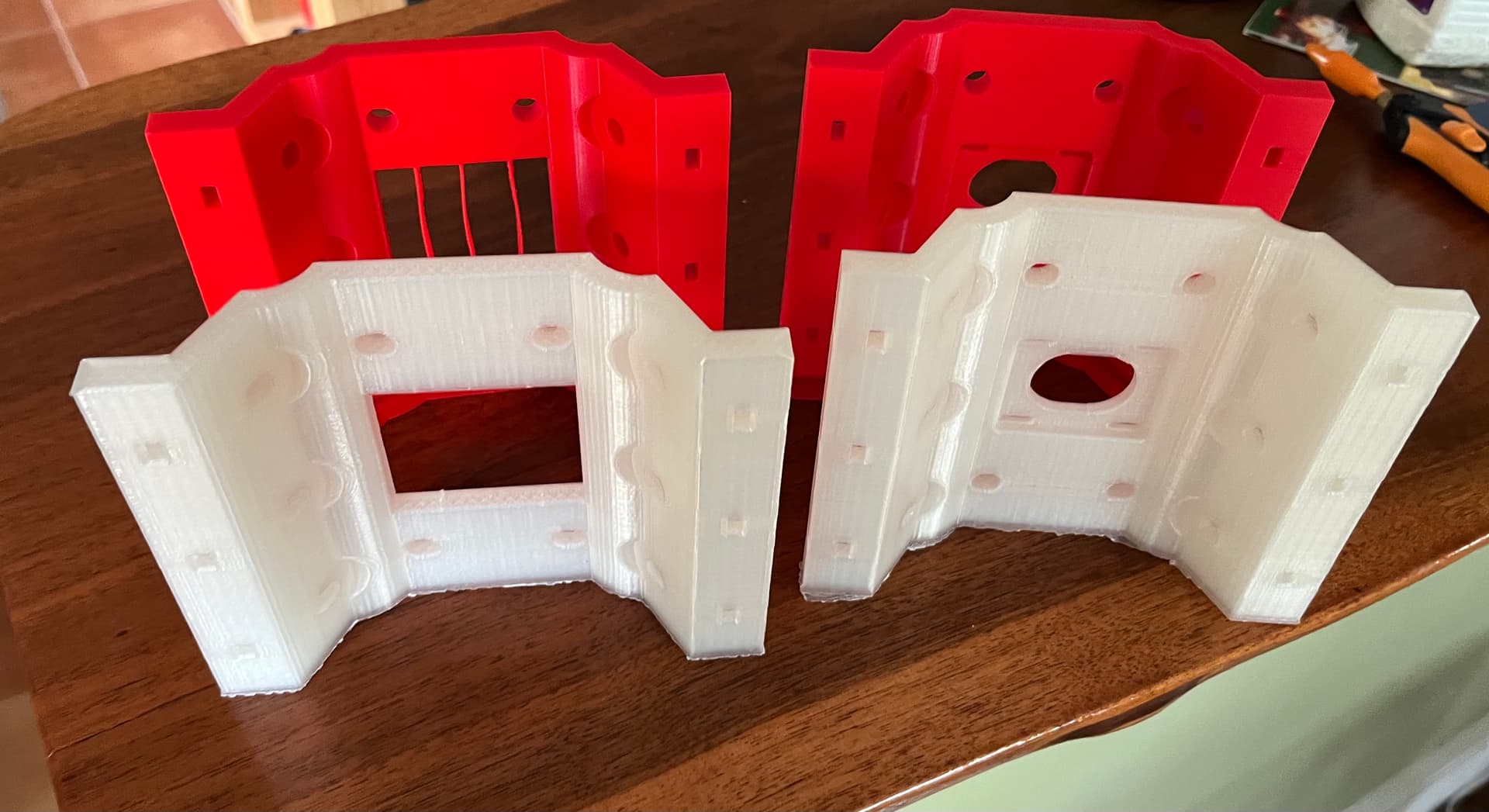
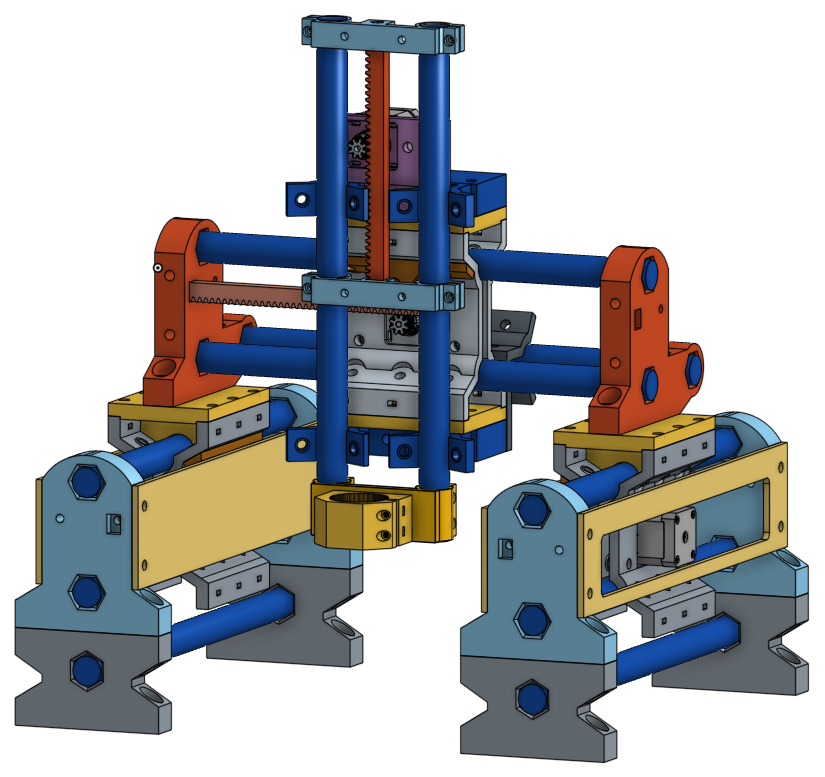
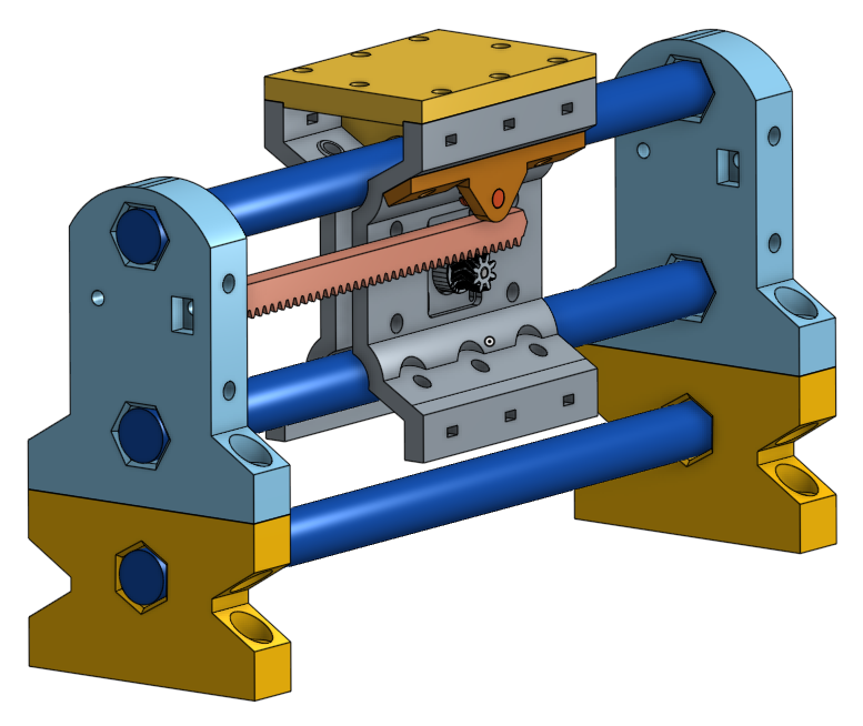
The solid side plates may, or may not, offer any real stiffness/rigidity gain but may be more helpful keeping at least some flying debris out of the R&P drive. The slotted side plates on the other hand probably don’t do anything at all… possibly adding spacers to clear the motor would allow for them to be solid as well, forming a more box-like structure. I put them on the CAD model because the through-holes allow for a side plate on both sides… so it looks more complete?
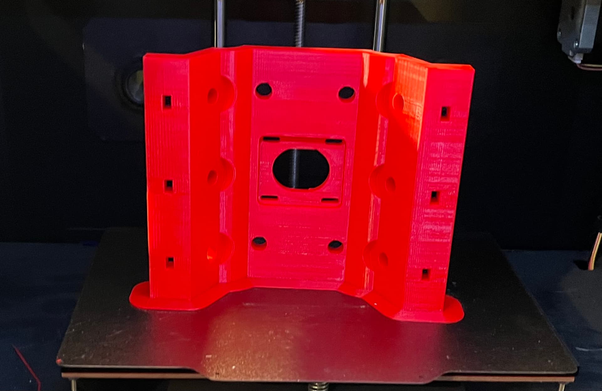
Parts are starting to come off the printer on this holiday weekend. Graduations to go to, RMRRF LR4s to drop off, lots of family stuff. But still some work taking place.
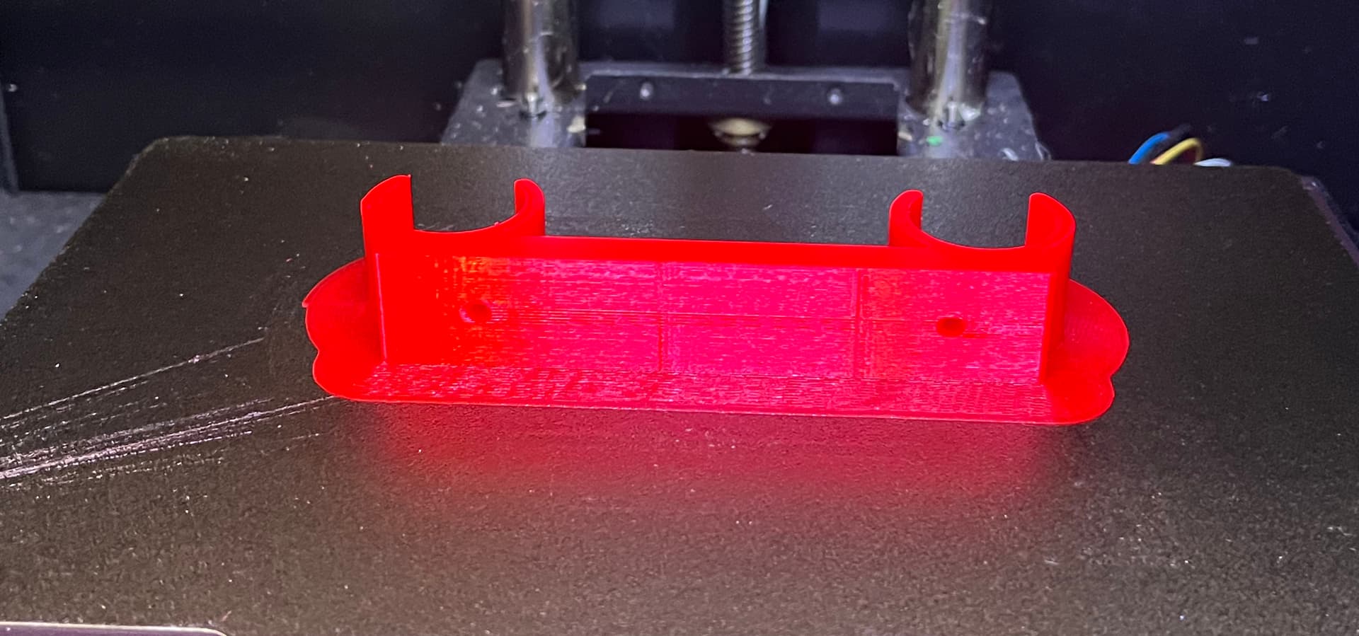
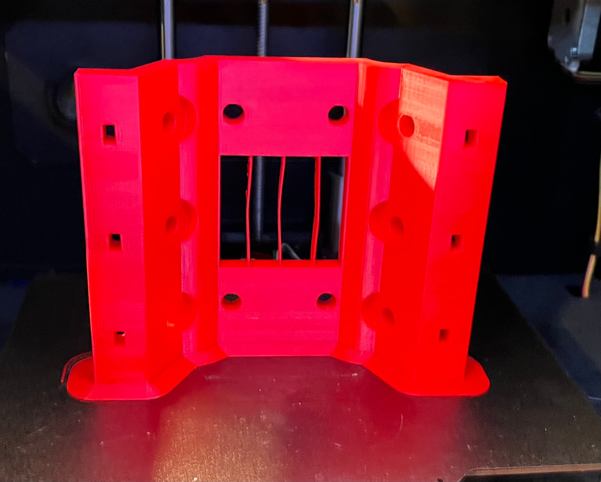
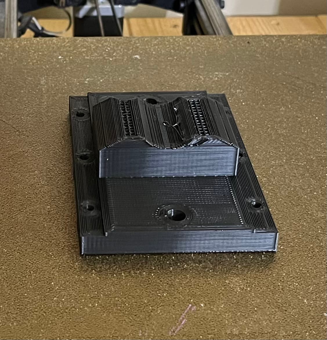
Cut it just a bit short on filament for the TAZ. I’m now officially out of 2.85/3mm PLA filament, so I either need to fix one of my 1.75mm toolheads or find more 2.85mm filament for this old workhorse. I’m not sure the last few mm of this part does anything particularly structural, so it will get used as-is. Not bad for a 10 year old printer and 4+ year old roll of filament.
About to run to the hardware store in search of M4 .7 x 20mm phillips screws and some m4 nuts. Sadly, I have lots and lots of other hardware but no surplus of those.
Pretty much the same here… grandson graduation and family stuff all day Saturday.
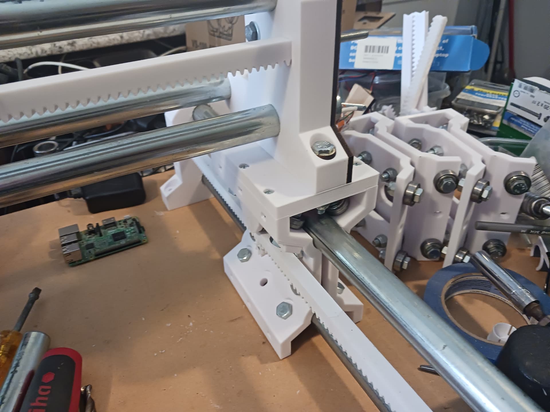
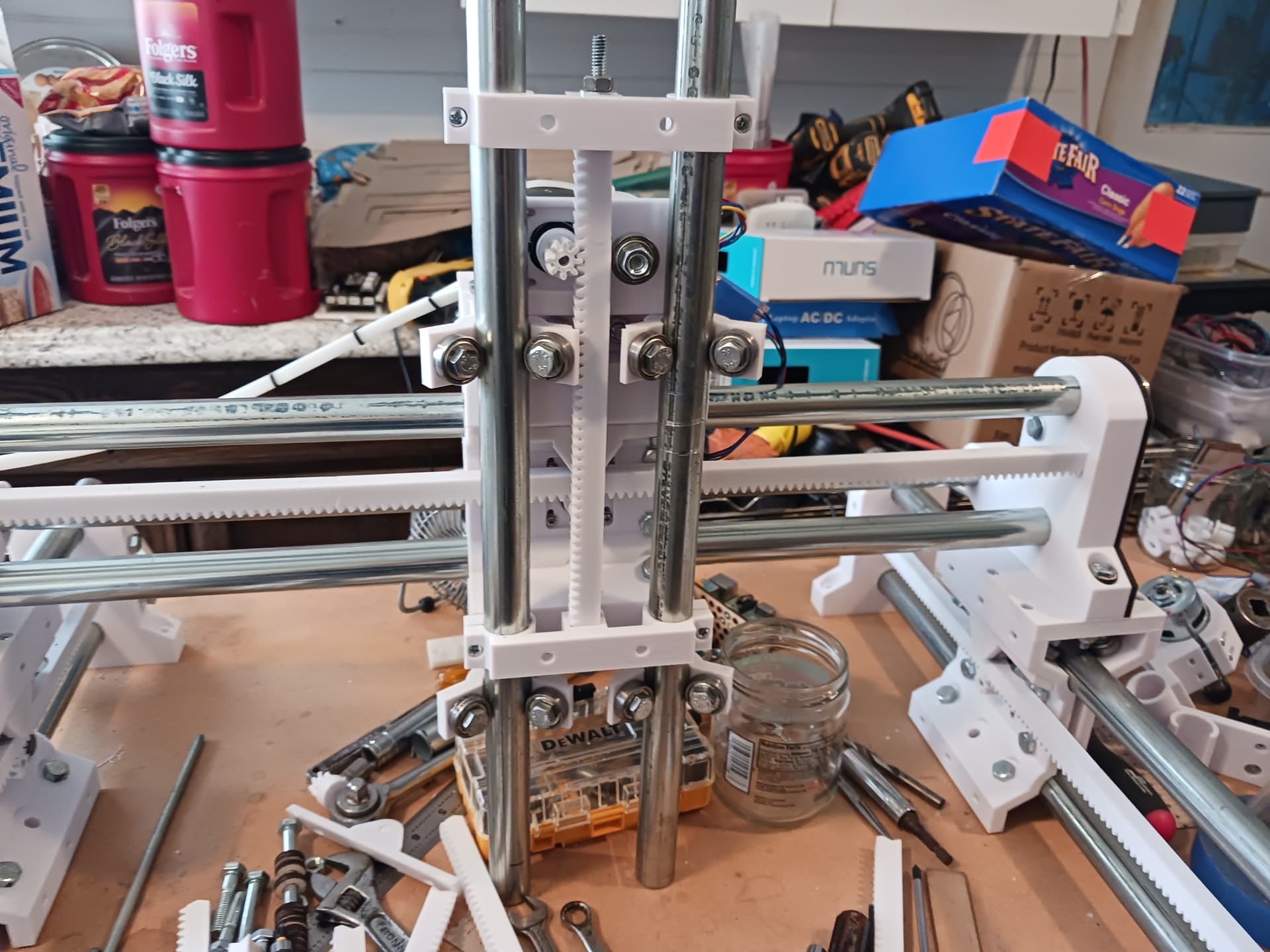
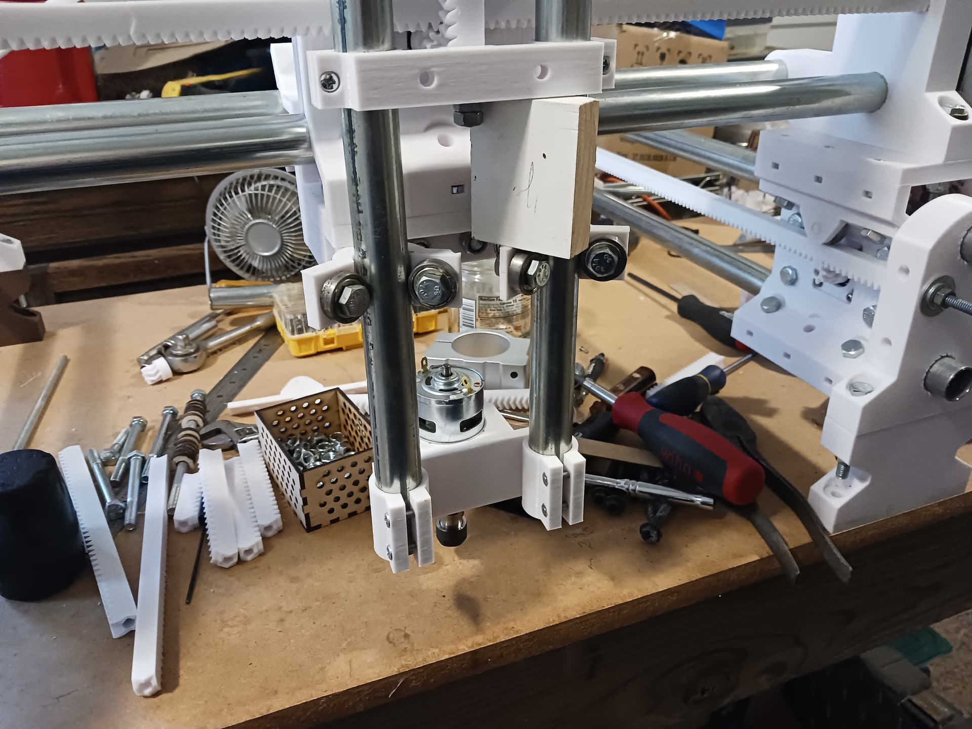
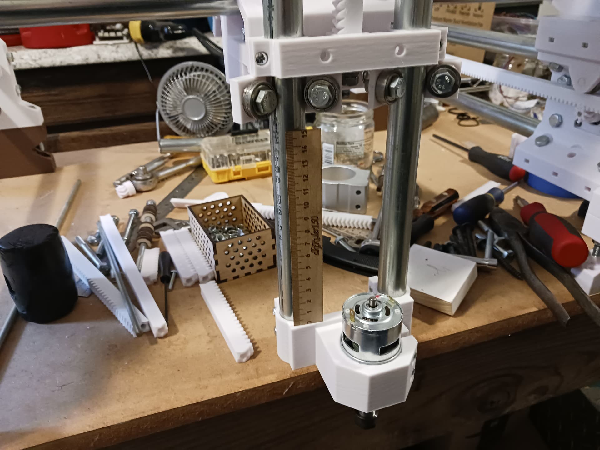
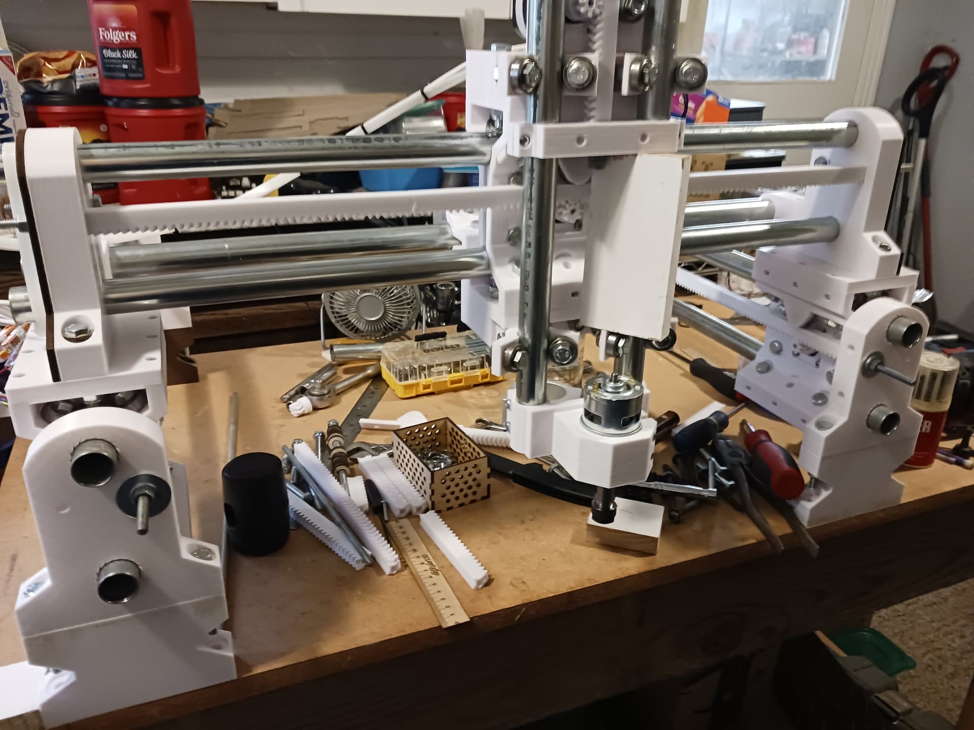
Added a 10-tooth segment to the Z rack and installed longer Z rails this morning… lets me see that I could/should raise the entire machine about 3" or so to allow enough room underneath to mount/exercise tools like a spindle and end mill. May also be better to actually mount tooling to an extended cover plate rather than the lower portion of the rails themselves that would allow the lower portion of the rails and rollers to be used fully and give maximum Z range of motion.
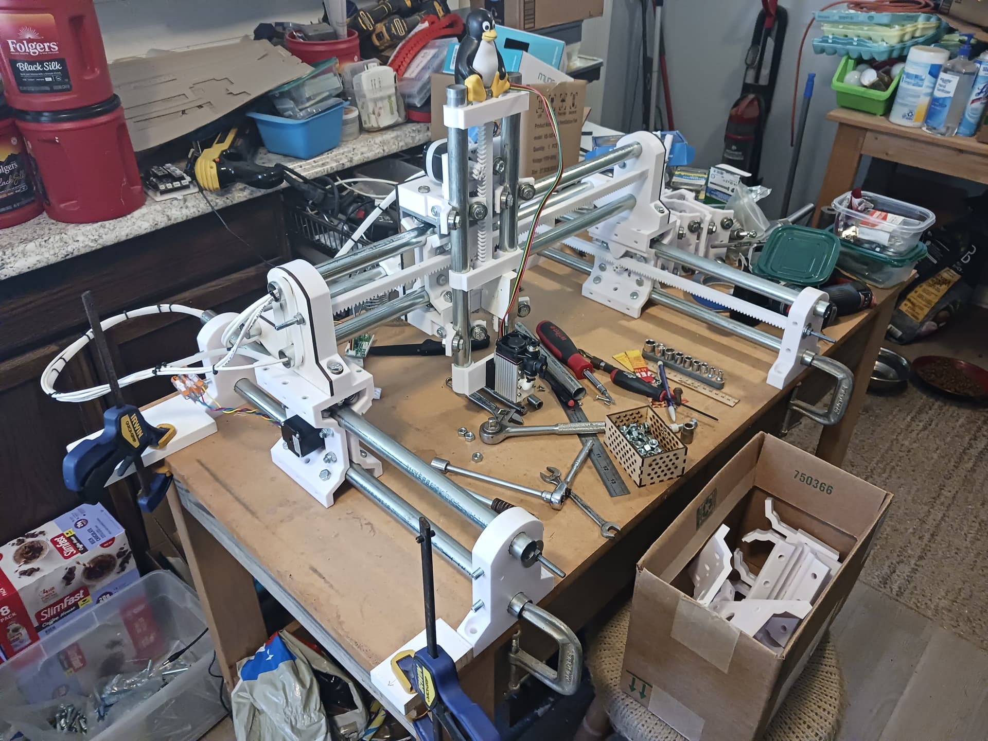
Managed to print 4 crude 3" legs yesterday evening before the strong storms hit during the wee hours. I decided to print them rather than simply chopping them from 2-by lumber because I could do that while watching the PGA golf tournament in Fort Worth and stay out of the warm humid shop and mosquito swarm’s reach. I also managed to mangle my Onshape models by changing the old “slotted_support” model (which I thought nothing depended on anymore…) without first copying it and making changes on the copy. I think I’ve recovered by backing up in Onshape’s timeline and creating a new workspace from before the legs were created.
My actual printed legs (also ran out of white filament) are minus the slot shown above…but now I’m thinking the slots and some conduit might make for neater, stronger(?), leg assemblies. I’ll continue to think more on the idea… but I’m pretty sure the 3" of added height is gonna be necessary to accommodate some types of tooling.
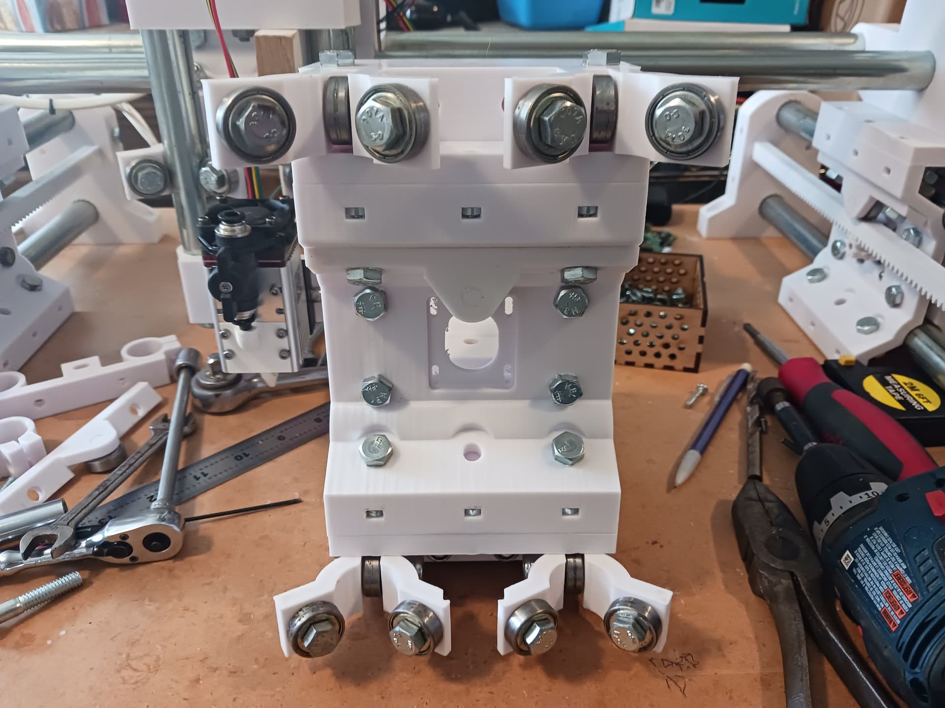
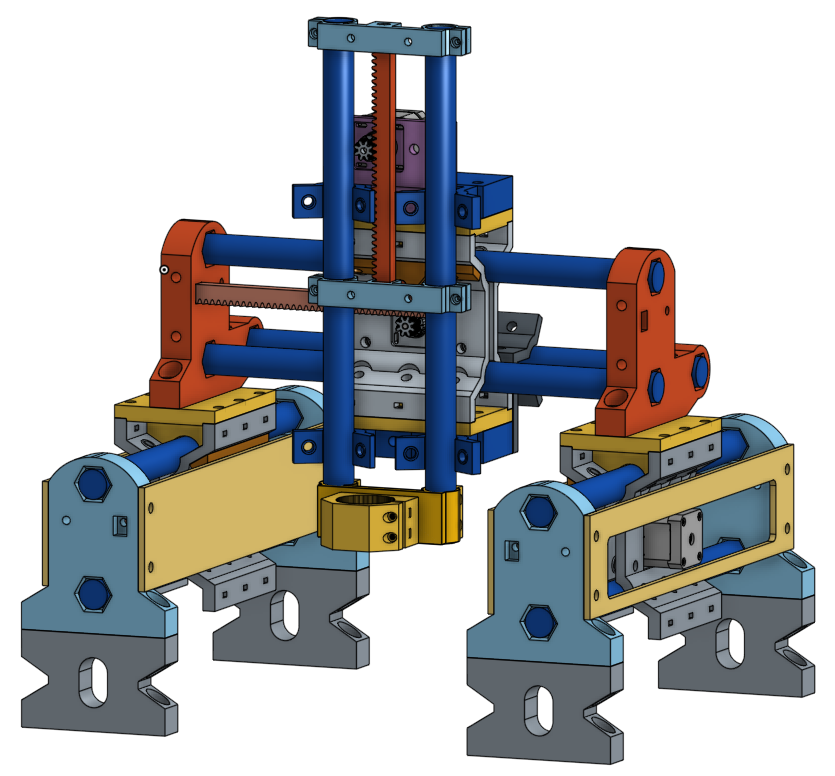
I suspect that ultimately the Z-roller assemblies, above and below the X-carriage, will be the weakest part of the entire machine. They could really stand to be reworked but for now they’ll suffice for further testing.
Still thinking a lower simple tool plate and the plastic cross-supports for the Z-rack could be beefed up and the existing holes used to mount a heavier wooden cover plate that could serve as the actual tool mounting plate. That would allow for a full 150mm of Z travel and also eliminate the possibility of warm/hot tooling ever being in direct contact with plastic.
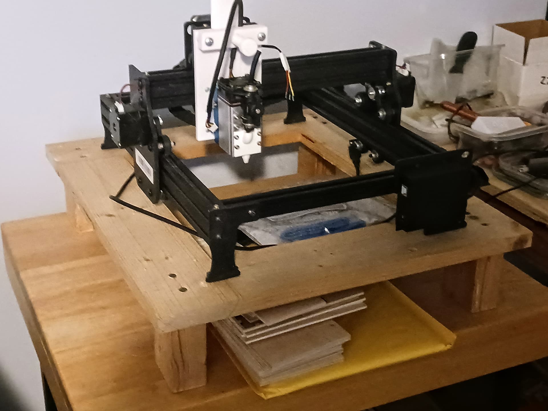
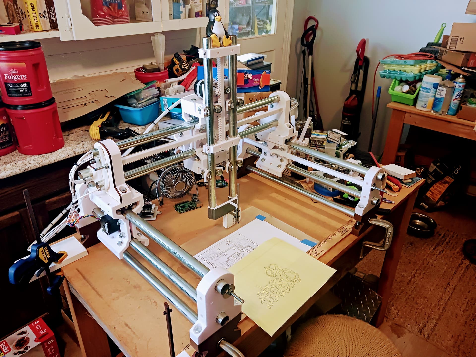
Got all the legs and upgraded parts installed and am now playing with it… pen plotting to start. I had tried to improve the accelerations early in my testing but the gantry has gotten so big and heavy it jerks and skips steps, so have had to back them off again.