Hello Ryan, thanks for the answer in uncle phils fbgroup, was very surprised.
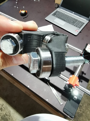
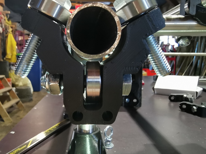
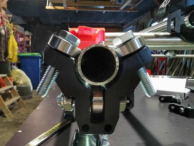
I did reassemble the core, according to instructions with not too much torque, just a few degree more after fit, but there is no difference, it’s still wiggling on both tubes.
I checked tube diameter, that’s fine, it’s around 25mm.
I bought the core from certified MPCNC 3D printer here in Germany (at least he is making promotion with that), after I kept failing printing on my own with PLA on my Prusa MK3.
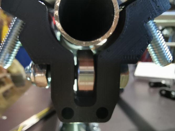
I also assembled a core clamp with bearings without tension, and there is always a lot of space between 1 bearing and the tube.
Don’t know what’s wrong, what should I do next?
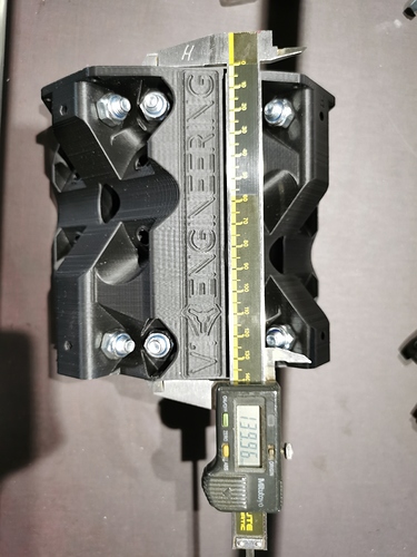
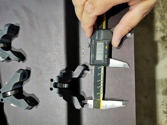
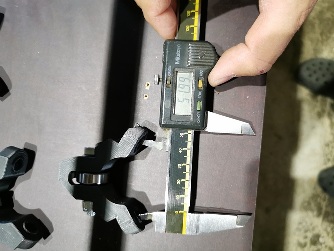
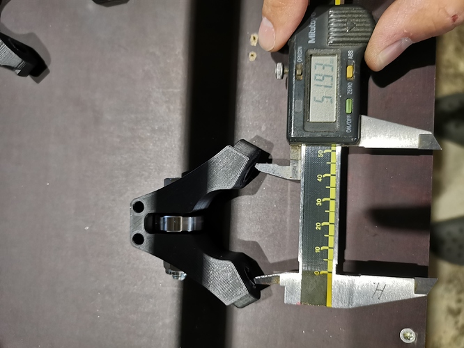
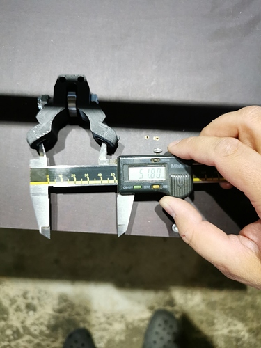
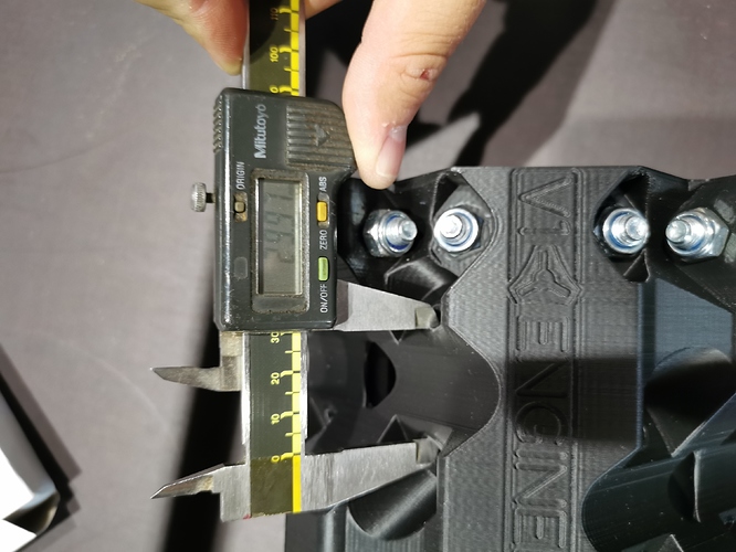
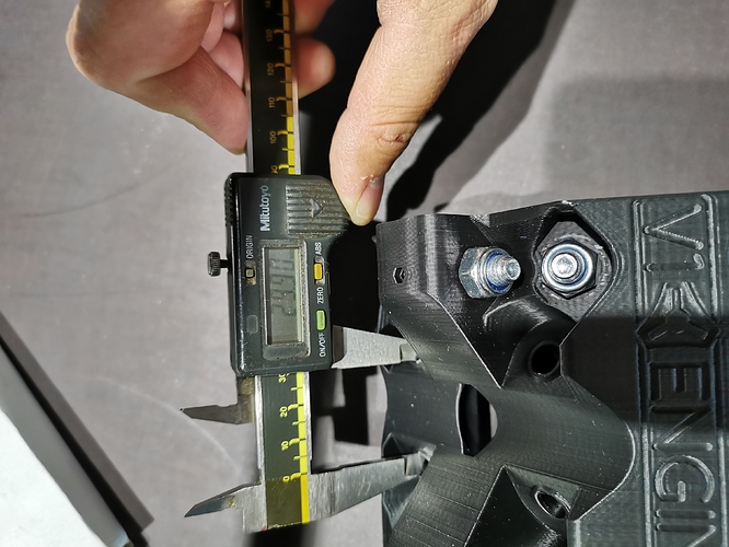
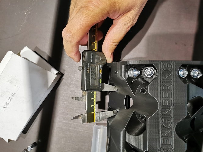
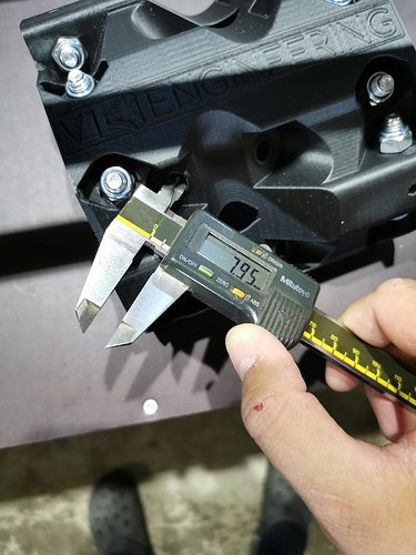
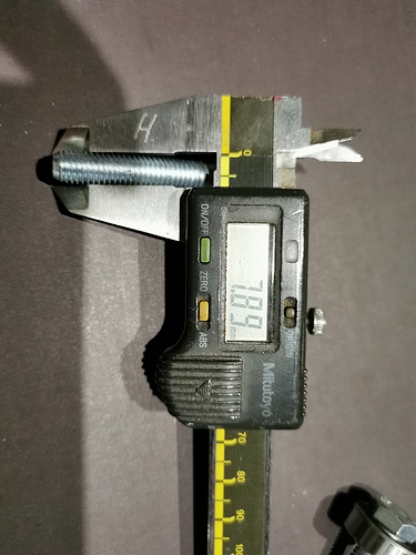
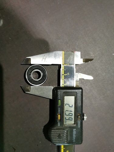
What is the caliper measurement of the PLA parts you are slipping onto the tube? And other dimensions? you can use for reference? Perhaps this certified source is not getting the right print to you?
I have exact same problem. All parts are printed. on Ultimaker 3. The trucks fit perfect around the tubes. The core is wiggling. Could it be that the core in the folder of F is actually the 25.4mm core?
Nevermind. It was already late while I tried to finish the core  After I tighten the bolts this morning everything fits perfect.
Could you please tell me than, what am I doing wrong?
I don’t want to over tighten the bolts, to find out if that is the problem.
Did you measure your parts like I did, are they the same?
First of all, I’m really new to this. This is my first mpcnc project.
I think you just need to tighten more. I had to tighten them really well in order to see that this was actually solving the issue far more then I did with the trucks.
If all the other parts are ok, then I would assume chances are small this part is printed wrong.
Without the nuts on the bolts those might be skewed and the ball bearings are not properly aligned.
The lower bolt tightens the “wings”.
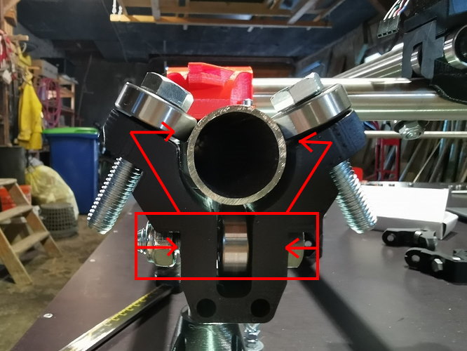
Just try it but do not overtighten the bolts.
Well, I did exactly according to instructions, after fit, just 1/16th of turn more.
When assembled to the core, the clamp wings can’t move anymore and instruction says it should be just fine without nuts on the last bolts, but it definitely isn’t.
I am pretty sure I will do make damage when I fasten more. I will do an analysis on the STL file of the clamps and check nominal condition to find out if the file is right.
…and your conclusion is…?
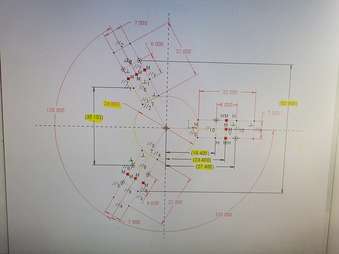
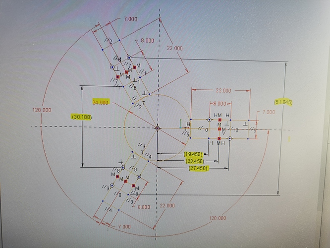
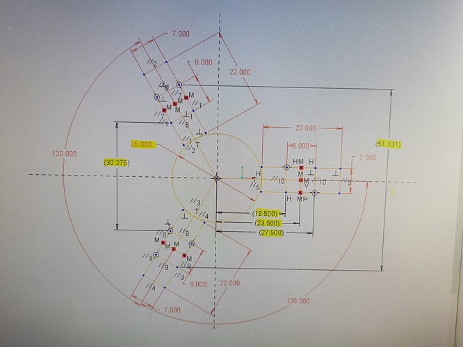
Not done jet, I have to get the used files from the printing service first. I just made these sketches to get an idea of how it should look like in the model in my opinion.
I’ve found the failure.
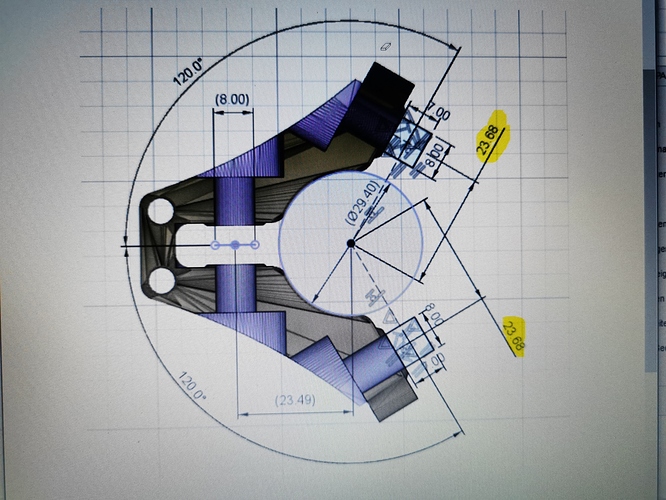
The Printing file on thingiverse can’t work, according to my investigations.
This dimension should be nominal without pretension max 23,5mm, with a little tension and regarding tolerance compensation of bolts, bearings and tubes, this should be max. 23,4 or even less.
Please let me know your thaughts about this, am I wrong?
The 23,49 is just touching, but with tolerances there would still be wiggle room.
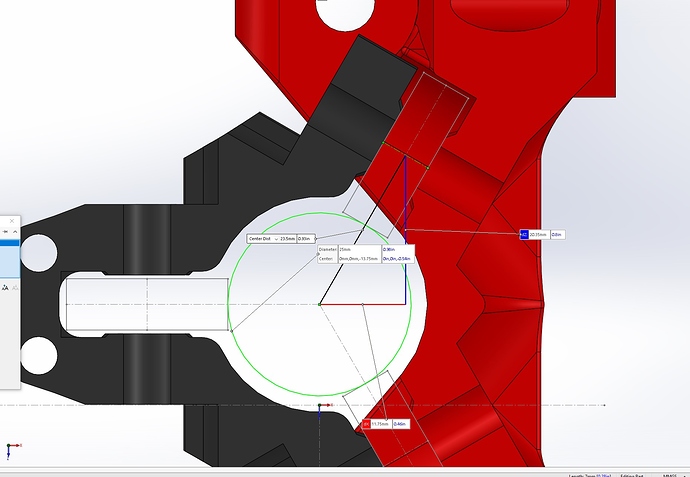
I guess I have to design my own Clamps with reduced 23,49 dimension down to 23 or less, as I don’t want to buy a new core.
What does the I.D. of your bearings measure? Sorry if i missed it if you already posted that.
I’m not at home, can’t check in detail. But they are 6082RS and should have 8mm inner diameter.
But for this calculation it doesn’t realy matter.
The tube has nominal outer diameter of 25mm the bearing has nominal outer diameter of 22.
So the distance between both axes should be nominal 12,5 + 11 = 23,5mm, without tension.
David had a problem that sounds similar, which was related to tubes being out of round. Texas Primo (Upgrading a part Burly/part 525)
I can’t speak to whether the design is intended to flex to accommodate the 23.68 vs. 23.5 difference, but I wouldn’t assume that it’s broken just because the numbers don’t match up. I am inferring from the instructions that the intent is to have them very loose to start with so they can be tightened just enough to bring everything in contact without messing up the squareness that was established earlier. If it was tight to begin with then it might tweak the rails out of square and there would be no way to loosen it to square it again. That is just me reading into it and I don’t know if that is the actual design intent.
The tubes are not perfect, but should be OK. Also from quick overview David’s problem weren’t the not round rails, but I couldn’t find the solution how he solved it.
As Rian suggested in the thread I could scrape or sand the standoffs on the core to bring the bearings closer together, or tighten even more as you said. But according to instruction overtighten is more worse than loose.
There’s a YouTube video in my thread with the fix. With everything assembled, I grabbed one of the tubes and rotated a bit. While I rotated it, the tube tightened in the truck.
