Make sure your bolts go through those holes fairly well, if you have printing defects if can impact this next step.
Take the rail out of the clamps.
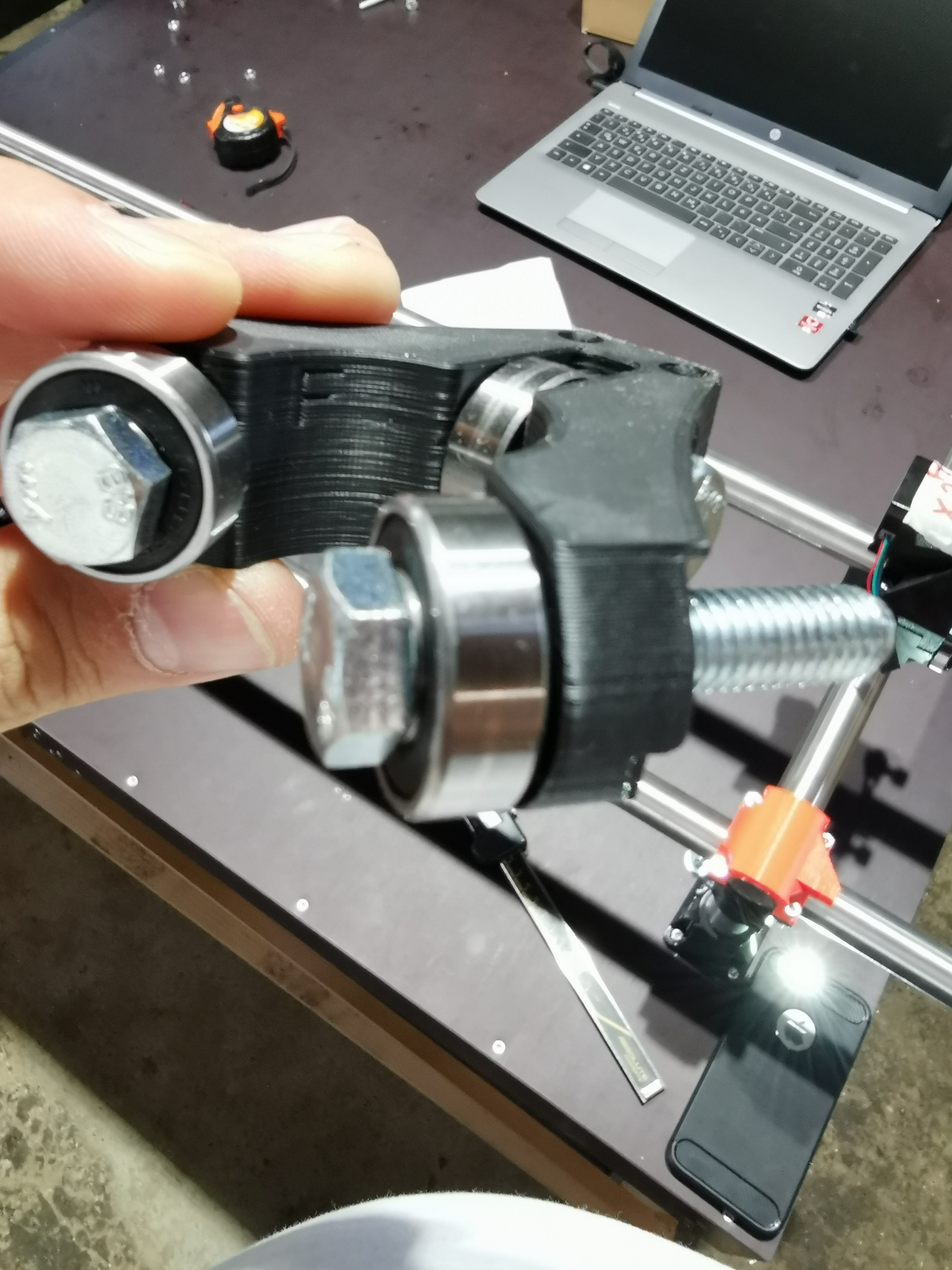
Put the bearing and tension bolt in to the clamps and snug up that bolt. This will pinch the clamp as tight as it can go.
With the clamp pinched bolt it back on to the core.
Take the tension bolt out or loosen it.
Put the rail back in.
That should assemble it to the core tighter than usual. My guess is it is getting put on stretched For whatever reason and will never tighten that way.
Like I said before, plan B is remove a little of the bearing stand offs, you can more it up to 2 mm tighter that way (1mm on each side).
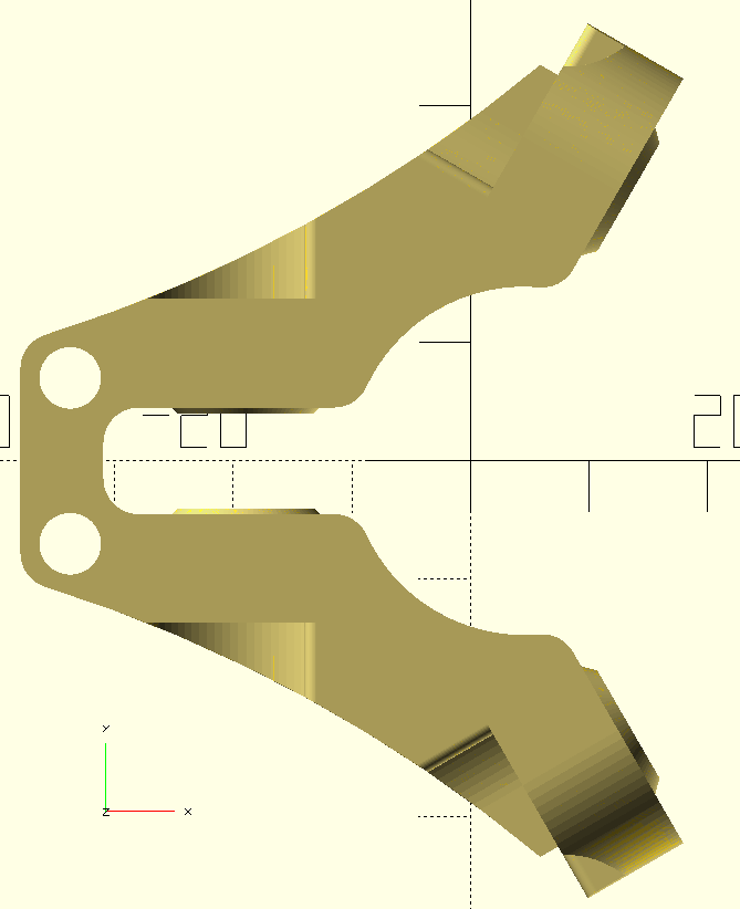
OK, I measured the dimensions in the STL as good as possible.
Could you then please check STL once more, because the STL from thingiverse does not match your design, as far as I can check.
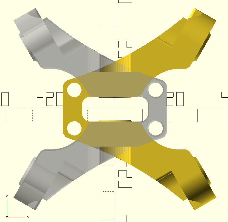
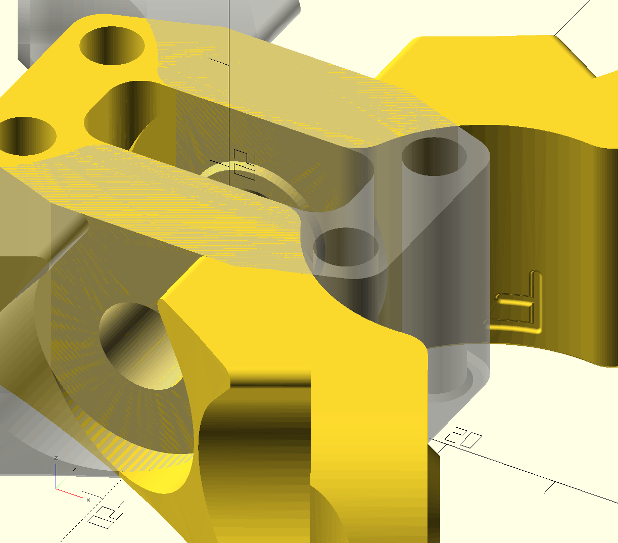
I used your dimensions to show the difference on the STL from thingiverse. The square is the bearing inner bore, wich does not align with the bore of the clamp, where your model says it should.
One more point:
You have sketched the bearing in your model, with an axial distance of 23,5mm between bearing and tube. But does the bearing bore align with the core and clamp bore, is there eventually the small deviation I am measuring in STL?
Then shift in X so that the bearing holes are aligned when the part is rotated by 120 degrees. Incidentally, the offsets are not the same for the inner curve around the tube compared to the bearing holes.
for (i=[0, 1])  rotate([0, 0, i*120])
// translate([-114.535, -136.914, 0])  // for the tube curve to line up
translate([-114.6395, -136.914, 0])  // for the bearing holes to line up
if (i) {  %import("Core_Clamp_F_Primo.STL");
} else { import("Core_Clamp_F_Primo.STL");}
No, I’m not at home until tomorrow.
But I doubt it will help, as the core will spread the wings again.
But I have the STL from a guy here in Germany who exactly hat the same problem, also others told me so. Sure there are also people who didnt had these problems, but I’m definetly not alone. I guess by overtightening the bolts on the core the horizontal bearing will move towards the tube, maybe they did this.
He fixed it by modeling his own Clamps with moving horizontal bearing 0,55mm closer to the tube.
I am looking at the model checking for any issues as compared to the 25.4. Everything is the same offset wise.
There are tons of 25.4.
If the part needs to be fixed I need to find a inconsistency first. But what you are describing is just an assembly issue, or possibly a print issue causing it. No point in over analyzing parts until you try a different assembly approach. You are bringing up an issue two other experienced builds had with the 25.4 version and both worked out in the end.
If there are others with this issue they need to speak up HERE, I can’t check every group on every platform. So as far as I know you are the only one with the issue and no one has brought up any other 25mm problems here, at all.
Also you assume it is the clamp, that is the easiest part to make and it is 100% derived from the core. I have been checking the core more than the clamp.
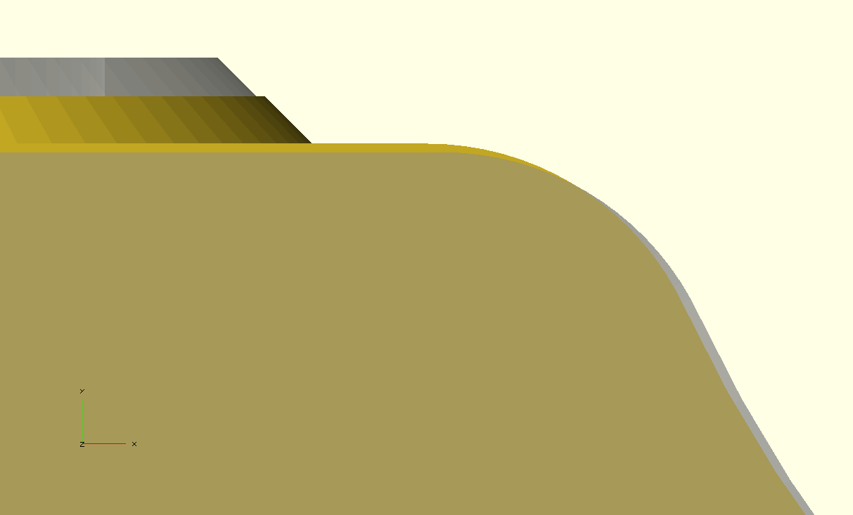
If your printer has acceleration issues (too low of accelerations) you will get a large bump on each of the Core and clamp bearing stand offs. One of the only places I do not have a round corner. 90 Degree corners are easy place to get print issues. Since this would occur equally on two parts the error stacks up. You can easily move the clamp 1mm+ too far out. If you tighten the two bolts that go into the core a little extra it will most certainly pull it in nearly .5mm, and if there is a faulty print, you could bring it in even further, as the acceleration bumps will easily crush.
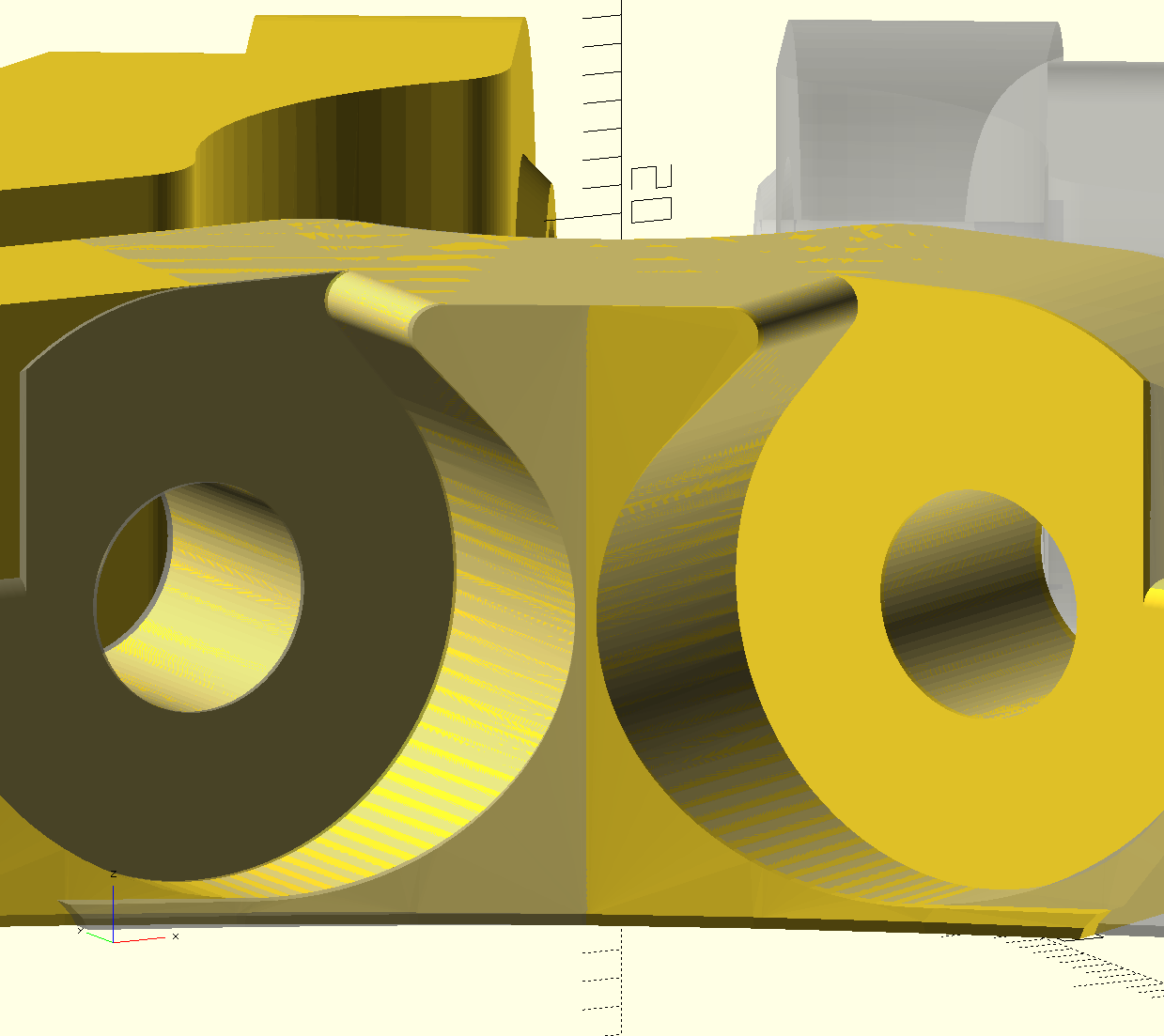
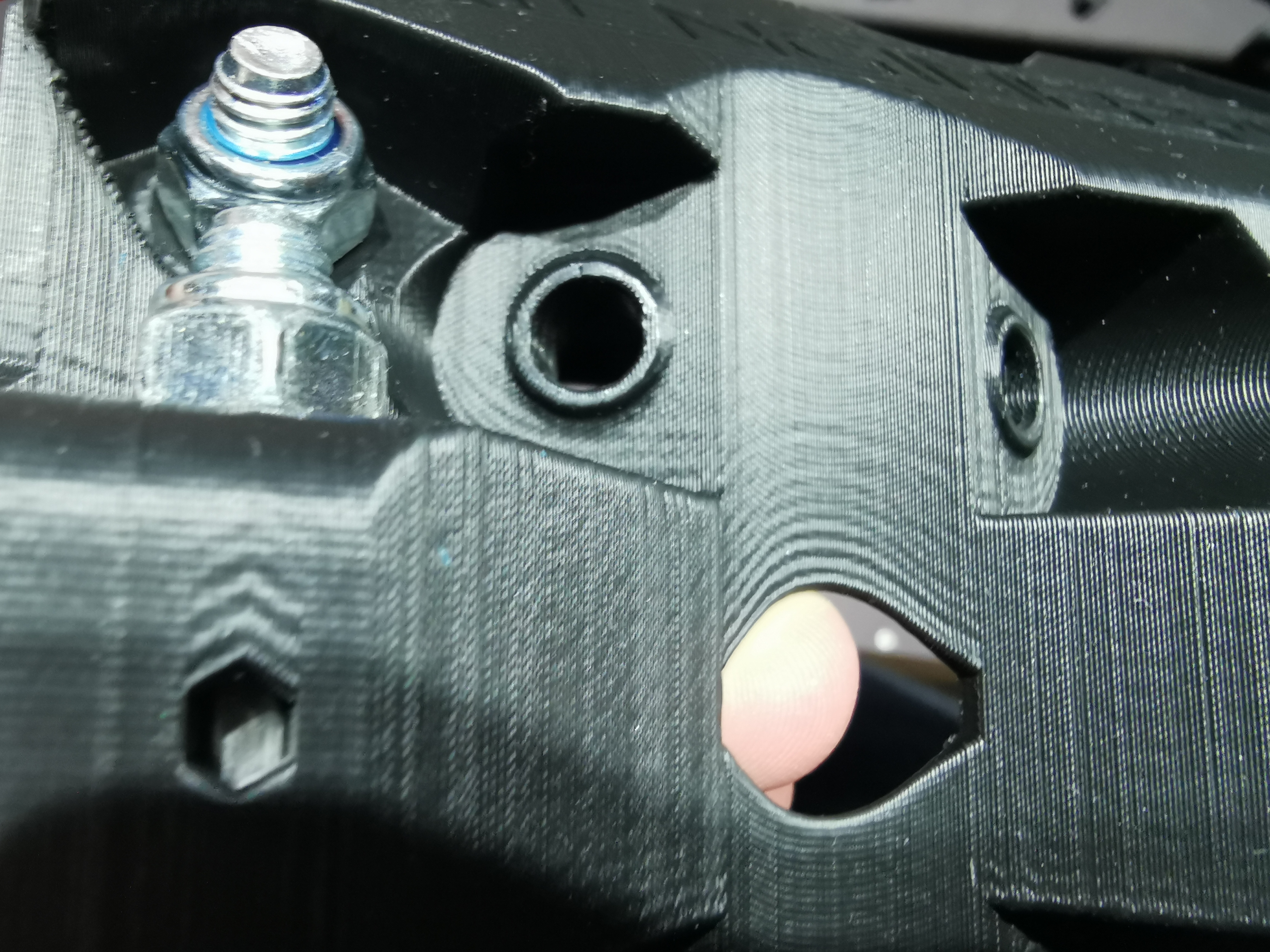
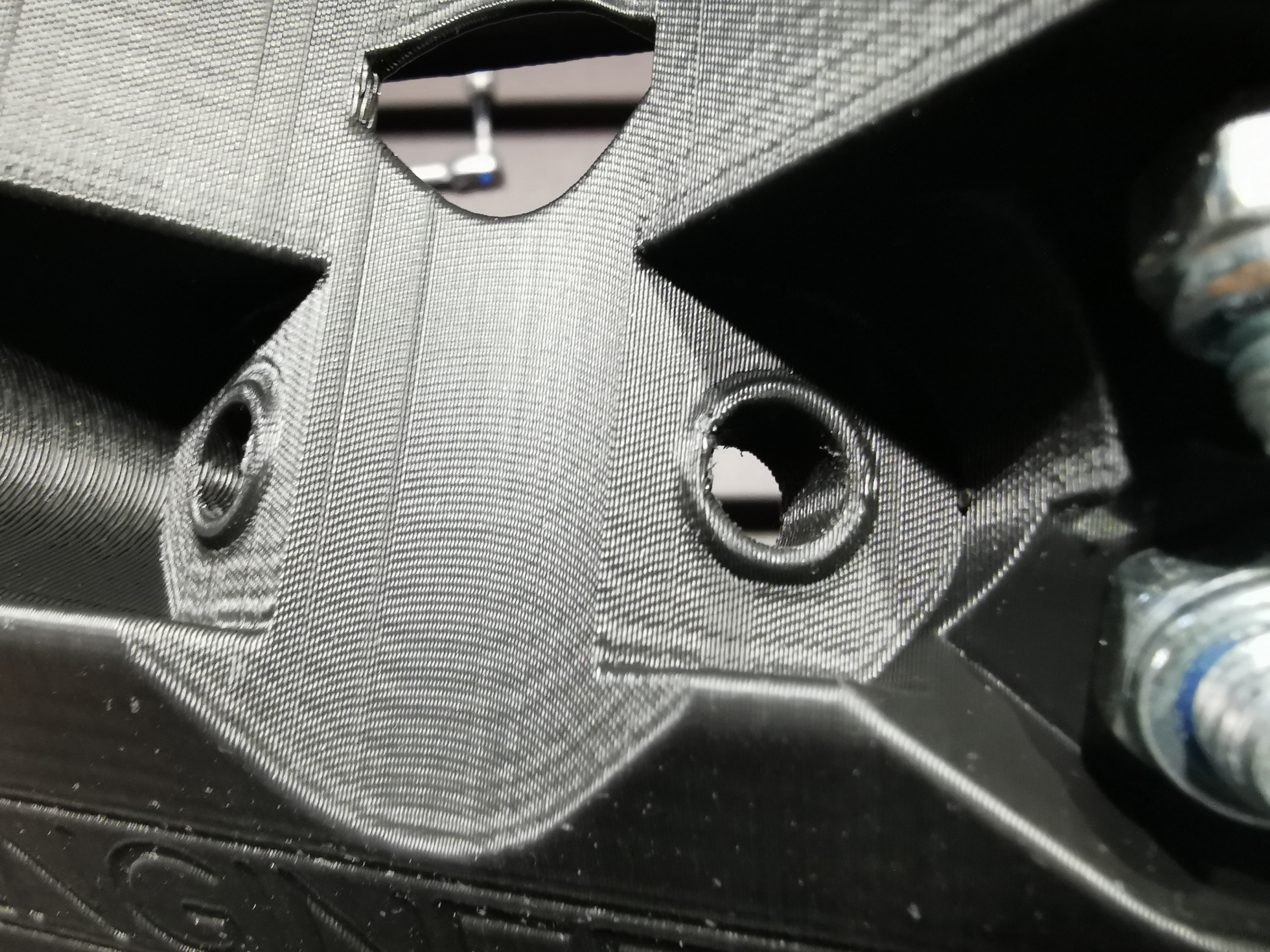
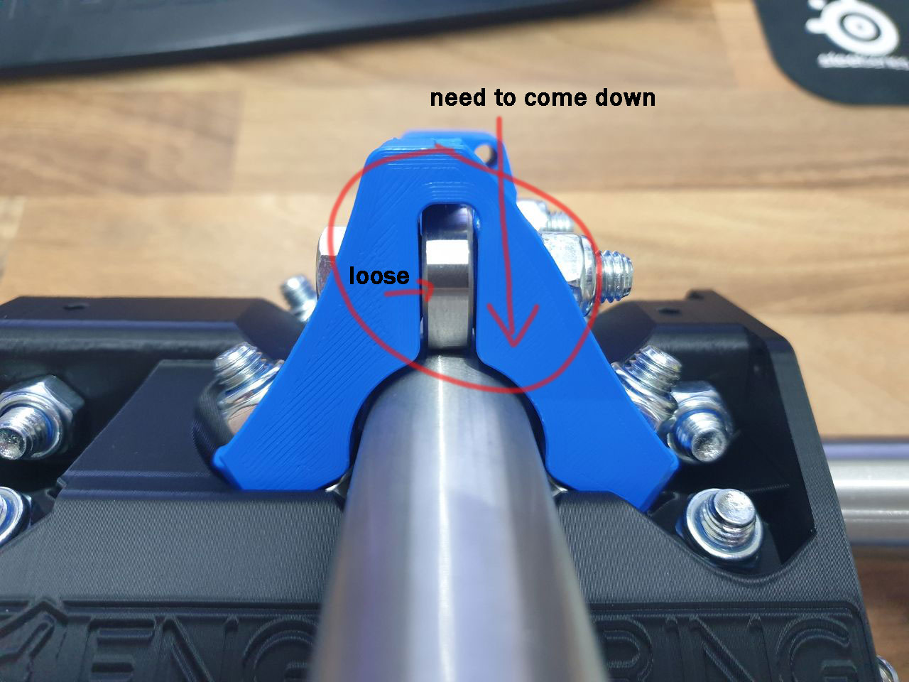
Can you show a picture of your bearing surfaces with no bearings, or bolts.
You should have slightly shiny flat surfaces from the bearings fully seating on both sides. If it is not perfect all the way around it is getting assembled crooked, if there is no shiny surface it is getting assembled too loosely.
I will check this when I am back home. I didn’t print by myself, bought it from a certified 3d printing service, at least he makes promotion with that.
Yes, I sanded the core and clamp standoffs and tightened a lot harder. It’s better, but not good yet, maybe a little more sanding. I realy don’t want to give more torque. But sanding isn’t very precise.
Maybe let it settle till tomorrow and tighten a few degree more. I’m quite double minded.
My tubes are roughly between 24,85mm and 25,05mm, I would say this is as good as you can expect for a handrail…
Straightness was maybe 1mm of per meter, before I started assembly and finding solutions.
Hey, i just finished printing my parts and started assambling. My is wiggling too but only a bit. All other parts were perfect fitting.
Tightened the bolts very much make it better but endet in a little crack in a clamp. (not much a problem i make a new quickly) but thats not the solution.