PRIMO Core-Adjustment-Tool for High Precision and Stability

Hi,

presenting my version of the MPCNC Primo ( My Primo in Multi-Colour, Multi-Material on a Alu-Frame 30x30 B-Type Nut 8 ) I have mentioned to realize some tools for core adjustment. Current problem is that the pipes between the trucks are not really orthogonal to each other. My pipes have an angle something between 89° and 90°. :rage:


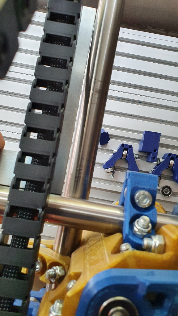
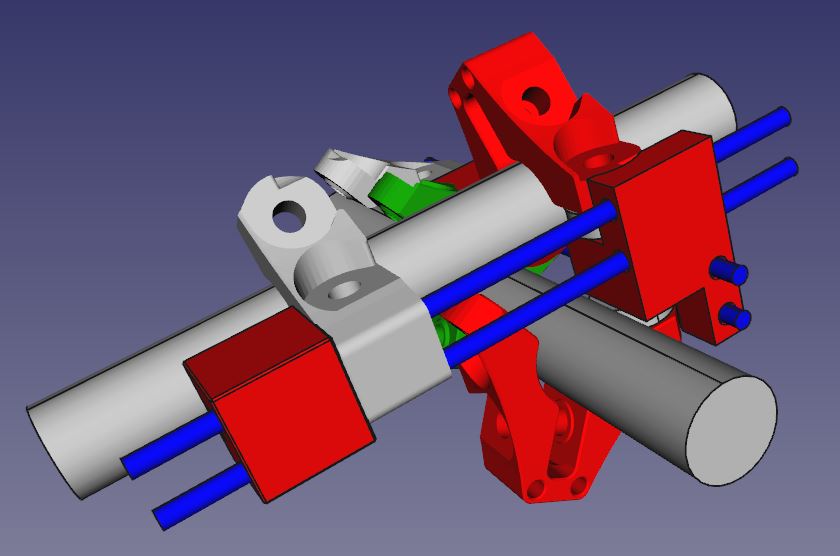
On the image above you can see that there is a small “distance” of ca. 0,5mm at the perpendicular axis which need to be reduced to zero.

Trying some design I came to the end:
Why not using the standard components and creating some parts for connecting them with additional possibility for adjusting the core pipes!
So I have used the core-clamps with the 2 holes at the top.

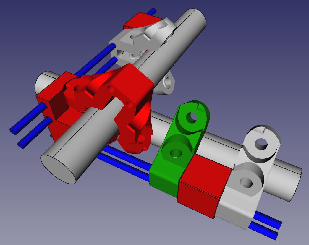
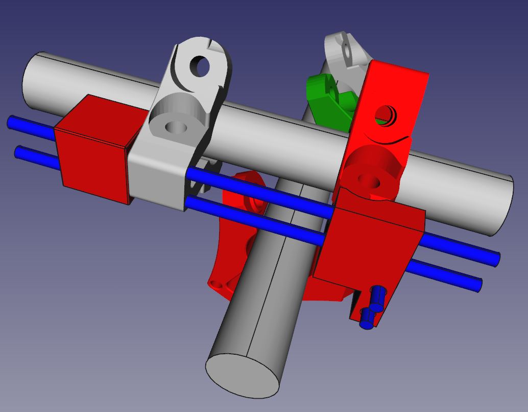
Here the design of my Core Adjustment Tool:

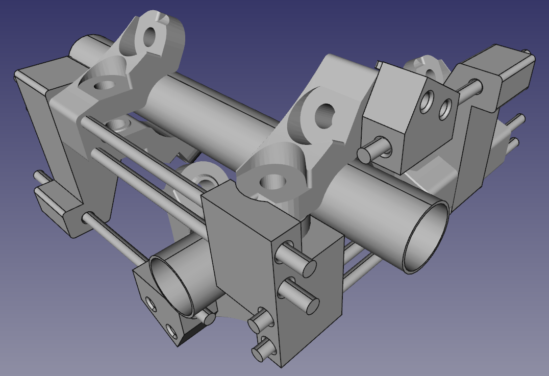
For my Tool I needed to print out 3 of the core clamp (Core_Clamp_F_Primo_V1.STL). 2 clamps I used for the adjustment tool, 1 clamp was needed for replacing the Core_Clamp_Y_F_Primo_V1. Replacing that clamp I lost ca. 5 - 6 mm of my working area (I think that’s acceptable :sunglasses:).

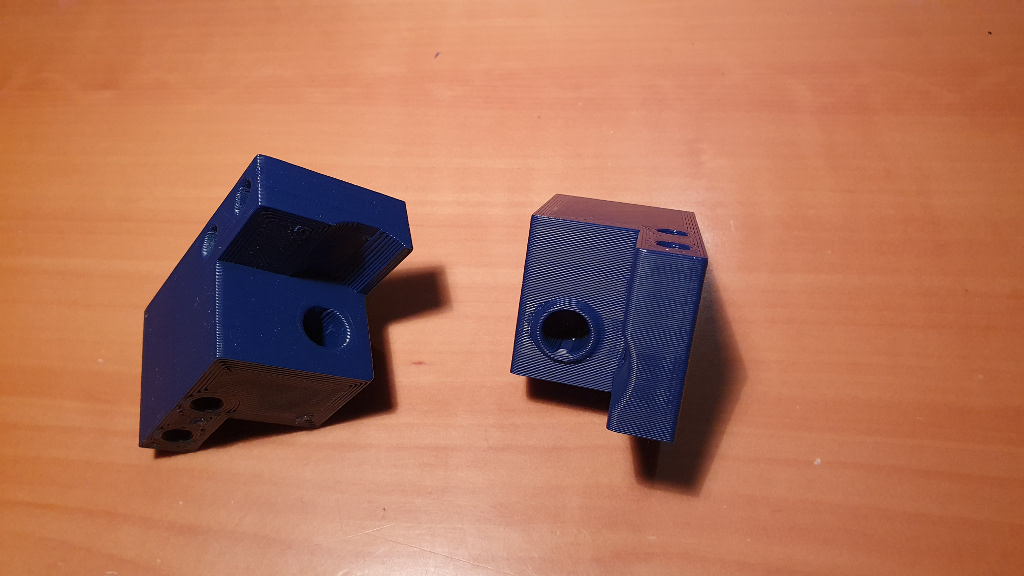
Here the parts I have created additionally to the standard Primo Parts.

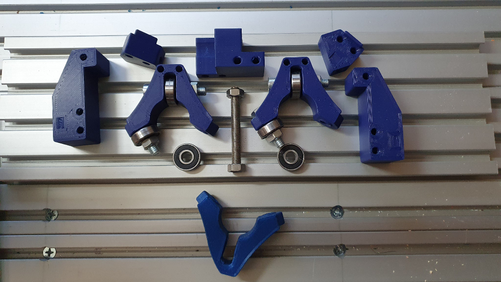
On the bottom of the image above you see the clamp that need to be replaced.
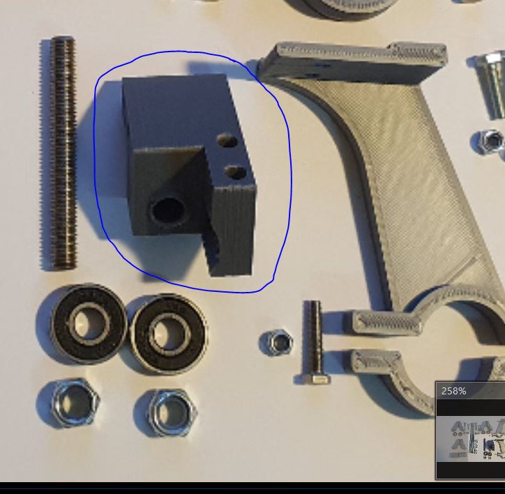
The funny thing was, it worked directly from scratch, I had to print out all parts (except one) only once. All parts with the threat rod, screws etc. directly fitted perfectly.
1 part I had to modify a little bit because while mounting the bearing I saw that I forgot a small feature. Dimension, holes etc. were absolutely correct.

The right part works because with the left part the bearings - of course - couldn’t move.

Beside the printed part I also needed:

4 x threat rod M5 17,5cm
4 x threat rod M5 6cm
2 x threat rod M5 11 cm
1 x threat rod M8 8cm

6 x roller bearing
2 x screw M8 30mm
3 x screw M8 50mm
6 x nut M8
32 x nut M5
32 x spacer

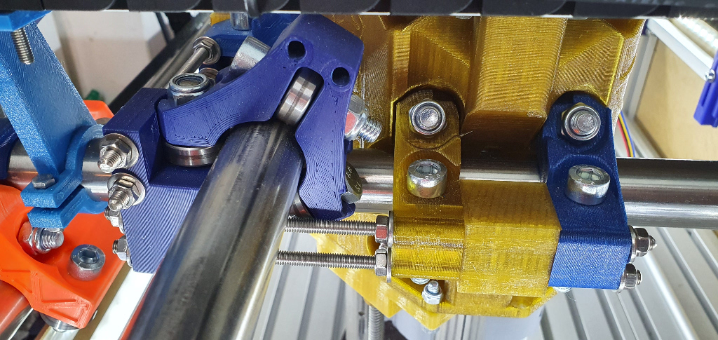
And so it looks with the PRIMO:

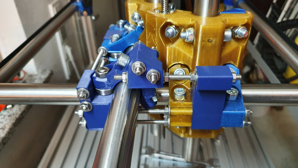
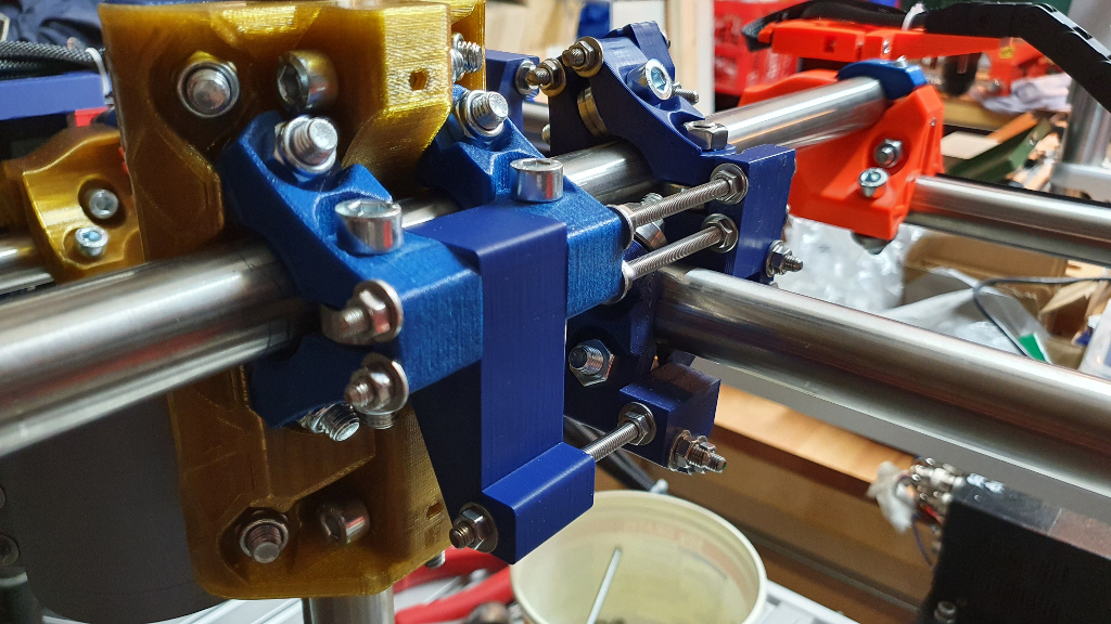
So with that construction both pipes of the core are really orthogonal!! And the stability was also increased a lot!!

Of course, it needs to be said, I think you can adjust imprecisenesses of up to 1 - 1,5°. I do not believe more. If the incorrectness is more than that angle, you will have another problem that should be solved before.
But with this construction it is possible to reach the last optimizations, and it works!! :crazy_face:

Ciao
DJ

2 Likes

Hi,
I have uploaded the parts to Thingiverse, if someone wants to test it. If you install it, please give me a feedback how it fits and works on your Primo.

  1. Upgrade:
    For the reason that the tool mounts quite high and most of the drag chains mount are too low, I have created some new drag chain mounts, that are high enough!
1 Like

This looks impressive. Do you have any other hobbies? :stuck_out_tongue:

Too much, this is the problem … oh no, it’s not a problem! :stuck_out_tongue_winking_eye:
The design took me only 5 - 6h.

I forgot:
I mentioned, that with the tool the working area will be shrinked for 5-6mm. But this is only in x-direction. In y-direction it is little bit more, round about 30-35mm. But in my case that’s OK. Better to be more precise than to have a larger working area.

1 Like

An impressive construction. I wonder though whether it would be possible to adjust the angle via the trucks. The standard method is to adjust the trucks so the gantry rails are square without the core, and then they are assumed to stay square when the core is added.

If they don’t stay square then I still wonder if some offset in the trucks could compensate.

Hi @jamiek

I thought so, but couldn’ find a way to realize it. With the trucks of course no problem but when adding the core I got a small inpreciseness - as shown above in the first image. Tried a couple of things to avoid it, but no way. And not only on the x-directions but also on the y ones.

For that reason I created this tool. The parts I want to “produce” should have a tolerance max. of 1/10 mm. And the material will be Aluminium AW 7075 (so real high strength Alu and Carbon which is no problem only for the dust - which is really toxic).

But for the carbon I will build a water basin for the Primo so that I can mill the carbon material under water … but first the Alumimium parts need to be produced!

1 Like

This is a pretty cool design.
A quick question: I’m trying to get my head around this, and I wonder if all it would take to make this work for the 25.4mm version would be to use the appropriate core clamps?

Hi Darell @BonzDarrell ,

give me some hours to check that. I will try to find some time this evening to measure it in the CAD. Should not be a big deal to adopt it to 25.4mm version.
I have also modified it to make it somehow easier.

Ciao
DJ

Hi Darell @BonzDarrell,

I have modified the parts to fit for the 25.4mm version, but I can’t test if it is really OK.
Of course you need to print 3x Core_Clamp_F_Primo and the parts from the attached zip-file. The included Drag Chain Mounts are higher because of the construction. They are modified for 25.4mm.

Core_Precision_25.4mm_Version.zip (150.9 KB)

My only doubts are for the center part. Should fit but I am not 100% sure

If in your opinion it is necessary to be changed, give me a feedback how and I will do that.
Ciao
DJ

Very cool! I will see if I can get my son to print this in the next couple days. I’ll let you know the results.
Thanks!

Looking at the pieces, the drag chain mounts are optional, correct? They aren’t structural to the core support?

Yes, that’s correct. I have added them only because if you normally use drag chain mounts they might be too low.
For the core support they are not necessary.

My son printed the 3 core_clamp_F_primo parts, as well as the two blocks and the corner piece that you designed. I received my order of bearings, threaded rod etc. yesterday.

So I’m trying to get my head around the 3 core clamps. I can see that one will be used for the corner block (the piece you have circled above in the picture). And one will replace the “core y” clamp that has the notch out of it.

But I can’t figure out where the third core clamp is used.

Maybe an overhead picture of the whole assembly would help my understanding?

Thanks!

Hi @BonzDarrell

sorry for the delay. Here some shots of the CAD system. Red coloured are the parts of the adjustment, green is the clamp that was replaced.

So you can see, that both clamps are connected to the center part, one on top, the other from the bottom, holding/guiding the center part.


Hope that helps.

Ciao
DJ

1 Like

Thanks DJ! That makes more sense. After work today I’ll head out to my shop and get this assembled.
Thanks!

Hi @DJPicasso

This idea is amazing. I have only one concern: How much stress/pressure will receive the center part?

How is your precision and stability after this? Will this help to reduce shattering and vibrations?

Hi @josedgm

you needn’t to be concerned. The pressure to the center part is less than you think. But, of course, you need to consider, that the area you can precise the angle of x- and y-axis is probably about 88° to 92°, not more. If your angle is out of this area you should check your general construction.

To be honest, I am using a number of different ways for precision, stability, reducing vibrations etc.

  1. this tool to precise the angle of x- and y-axis
  • the center part and the additional clamps for the precision
  • the “cubes” between the clamps for stability. These cubes are helping a lot to stabilize the core and the clamps, really a big advantage!
  1. additionally my control supports autosquaring (electronically) so the angle is exactly 90°. After building the MPCNC I had - mechanically - an angle of ca. 91° and with the tool I got exactly 90°. Using the autosquaring func this tool is mostly for stability.
  2. additional clamping block for a thread rod nut (anti backlash nut) - this really reduces vibrations! I mentioned it here: Solving Z axis lifting problems, stepper losses
  3. I printed the MPCNC with stronger material: mostly CPE HP100 and ASA - really a huge difference to the standard PLA!

Ciao DJ

I tested out the core-adjustment-tool today…
After installing, I was able to tweak my assembly just a tiny bit, so it’s really, really square now. It seems stiffer as well.
As a side note, I forgot to re-tighten the clamps holding on the router, so my first 30 seconds of cutting was done at about 3mm with no apparent problems. I usually mill at 1.28mm DOC and want to be able to bump it up to 2.0mm - this accidental test seems to show that a 2mm cut in baltic birch should be feasible.

I took a video, but can’t figure out how to post it here. Maybe I’ll add it in on FB group…

Hi @BonzDarrell

sounds good! So the parts fit for the 25.4mm version. As mentioned above, with the cubes between the clamps the construction gets much more stability!
You should also test the additional clamping block with a anti backlash nut mentioned above! :wink:
It is a “small” add-on, but you will be surprised about the difference!

With my construction I mill up to 5mm DOC in aluminium and feedrates up to 800mm/min (trochoidal) without problems.

It is available also on Thingiverse now

1 Like

Thanks DJ - I read about the z-axis mod, this looks very interesting.
I wasn’t clear whether you re-printed the core with extra holes?
I’m not familiar with an anti-backlash nut, I’ll have to look that up.
I didn’t spot a link to the file, did you post that to thingyverse?