I get the general process. It’s just that FluidNC doesn’t seem to like feed holds in the macro or I have something not quite right. I have M6 macros working on my pen plotter. For that, I just took the defined process that was being used and “converted” it to M6 handling. That doesn’t require user intervention so there weren’t any issues.
For FluidNC, there is only one macro for all of it. When you execute an M6 command, it calls this single macro so it has to use the gcode parameters and expressions to figure it out. It gives you the current tool and the selected tool. There has been a change since the one I created for my pen plotter. When the tool change is complete, you need to actually set the selected tool as the current tool with M61 #<_selected_tool>. Unless it fails, then it should raise an alarm with $Alarm/Send=3.
For positions, my intention is to have variables that store the position of the first tool location and the spacing between. So, the X location is just X location for T1 + (tool number * spacing). All the tools should do the same thing, just at different locations.
As i said many times: the way to go is a bit setter with collars. You measure just the first time the z height ( all bits are going to have the same lenght or a difference rhats measurable and can be taken into account for the gcode.
Also kress/amb has a quick release version of the spindle (but again 700/900 euros🤑
I’m making progress. I created a simple test design that uses 3 tools. I manually updated the gcode to change the start and tool change gcode. I can get it to move to the appropriate tool specific change locations and probe and such. I haven’t cut it out yet since I didn’t incorporate the Z offsets yet. I think I have the logic figured out.
The Z offset part is something like this:
Probe Z on the fake magazine (piece of paper). Store the Z offset (example -68.885).
Probe Z on the workpiece (this is the only time it is probed here). Store the Z offset (example -49.350). Since the probing sets Z0, it’s good to continue.
Change the tool (I just pulled the same bit out further). Probe Z and store the Z offset (example -63.705 - so it’s sticking out an extra 5.18mm). Since this changed Z0, we need to get Z0 back to the top of the workpiece.
Take the Z offset from step 2 minus the Z offset from step 1 (example 19.535). This is the difference between the top of the workpiece and the probe location. Since my probe location is a piece of paper on the spoilboard, it’s basically the stock thickness.
Take the Z offset from step 3 minus the Z offset from step 1 (example -5.18). This is the difference in bit length.
Take step 4 plus step 5 (example 14.355).
Move to the Z position from step 6. This is the top of the workpiece with the new bit.
Zero Z at that point.
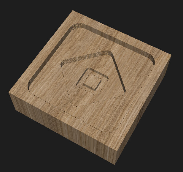
My test design is wildly inefficient for but good for testing. It’s 30mm square. The large square is a 2mm deep pocket done with a 6mm endmill. The diamond is a 4mm deep pocket with a 3mm endmill. And the middle square is a 5mm deep profile with a 1.5mm endmill. That should adequately test that I got the Z offset right. Ignoring probing and tool changes, it’s supposed to take 36 seconds.
Once I have it working with manually updated gcode, I’ll see where I can split that out into files or at least update CAM settings to handle it. Actually, I think that the only part that really should be in an external file is the variables that define the locations and spacing and such. I would just configure FluidNC to run that file on startup (as startup_line0 or startup_line1 macro). I probably need to prefix those variable names with an underscore so they have global scope to do that. Currently looks like this for me.
I keep perusing their site too. An 8 position with dust cover and tool setter and a set of their “collet shields” would run $880. I’d like to look into something based on a Gator Grip knockoff:
But “life” is currently occurring and I’m moving to a new home. So I haven’t had any time at all to look at a design.
Good news is - lots of new ideas for projects for the new house. Bad news is - absolutely no time to execute.
I got this figured out. I successfully made my test cut. It moved to the proper positions for each tool change and set Z after each tool change without re-probing on the workpiece. Too many iterations so I didn’t get a video yet.
I had a hard time figuring out how to set Z after a tool change. I apparently still don’t understand how offsets work. G38.2 sets an offset, then there’s G92 which is an offset on an offset, and then there’s G10 to set it right in G54. At first, I was trying to use G92 offsets for Z but when you already have a G54 offset set by the G38.2 (I think), then you have an offset on an offset and that confused me. I was cutting too deep. So, I skipped the G92. Then I was trying to use G10 with a non-zero value and messed that up so I was air cutting. Eventually, I calculated the new Z0 in machine coordinates, moved there in G53, and set Z0 with G10 L20 P0 Z0. I’m still getting G10 L20 and G10 L2 confused.
I’m sure there’s a better way to do that, but that’s what managed to work in my head and in reality.
Now I just need to clean it up and sort out setting the starting and tool change gcode in CAM. It’s not an issue in Estlcam but in Millmage it wants to do the same tool change gcode at the start and for tool changes (and it doesn’t like fancy gcode that could solve that problem).
I also need to make something new to test. This was tiny and in MDF without finishing passes so the result is pretty ugly. Also, tool changes that require changing the collet are really annoying. I’m going to avoid that in the future.
It’s been a while since I looked at all of this… It was hard for me to find a clear explanation back then, however, this was how I understood it at the time …
That makes sense. I was doing something like G10 L20 P0 Z-40.123 and that Z value was in machine coordinates so that was wrong. G54 already had a Z offset from an earlier probe. It looks like if I used L2, it probably would have worked. So, I ended up doing this instead:
G1 G53 Z-40.123
G10 L20 P0 Z0
which based off your description would be equivalent to:
G10 L2 P0 Z-40.123
P0 (current coordinate system) and P1 (G54) are the same thing here.
Once you start doing more complicated stuff, I think you want to try to stay away from G92 unless you know for sure that’s what you want to do.
"G92 makes the current point have the coordinates you want (without motion), where the axis words contain the axis numbers you want. All axis words are optional, except that at least one must be used. If an axis word is not used for a given axis, the coordinate on that axis of the current point is not changed.
When G92 is executed, the origins of all coordinate systems move. They move such that the value of the current controlled point, in the currently active coordinate system, becomes the specified value. All coordinate system’s origins are offset this same distance."
I think it just muddies things up quite a bit, and mixing G10s with G92s makes it worse.
G92 is fine for most people because they aren’t doing anything else, and it’s easy for us support-wise because it’s the same for Marlin and FluidNC, but once you graduate out of that, G92 can be trouble.
I think I got myself it trouble with coordinate systems last week. I could not get my z-offset to work either. Any chance this is a firmware bug? like it comes with a preset Z offset somewhere?
I homed, moved to my starting postion, and ran the usual starting gcode that probes, g92’s, then starts. unless I zeroed everything out manually, it offset up about 25mm extra every single time. I forgot about that I made a not to look into it. I even made several different gcodes. running the latest fluid and your new UI
I mean I’m doing weird things here and I’m pretty confident all my problems were my fault. The start of this thing still follows the normal pattern with home, jog to start, and run including a G92. That part was never an issue.
I feel like I had something like you describe happen to me a long time ago. I used to always zero everything out before running a job but I haven’t done that in awhile. G54 offsets persist after restart but G92 doesn’t.
If it happens again, I would be curious what the $# output looks like.
This finally makes sense as to why G92 might not be desirable compared to G10 L20. I take it this means you can crash the machine by using G92 since the machine coordinates are shifted and don’t reflect the actual limits.
Someone once tried to tell me to avoid G92 “because it is not saved”. Okay, true enough, but so what? That’s a dumb reason.
But shifting machine coordinates sounds like a real reason.
 use Grbl_ESP32")