Pretend ATC Idea

I think ATCs are the coolest thing but I can’t justify buying one.

So, I had this idea where I could “pretend” to have/be an ATC. This is wildly unnecessary and probably dumb but that never stopped me before. :laughing:

That starts with being able to use M6 commands for tool changes. Right now, we add gcode from the milling basics page for tool changes that handles pauses and probing for manual tool changes. That wouldn’t go away.

FluidNC supports M6 macros on spindles. So, if you call something like M6 T1, it can call a macro to perform the tool change. The goal is to move that custom manual tool change gcode from the gcode to the macro. So, the CAM software just needs to add the M6 command.

ATCs also have a tool setter to automatically set the height after a tool change. FluidNC supports this for manual tool changes without an ATC through an “atc_manual” configuration. However, I don’t want to use a bit setter because I don’t want to run a wire from it to the controller. Also, then I can’t use the M6 macros I need to do the other ridiculous things I’m getting to.

Ok, Jason. Where are you going with this?

Well, here’s a concept of a pretend ATC magazine that I whipped up in MillMage:

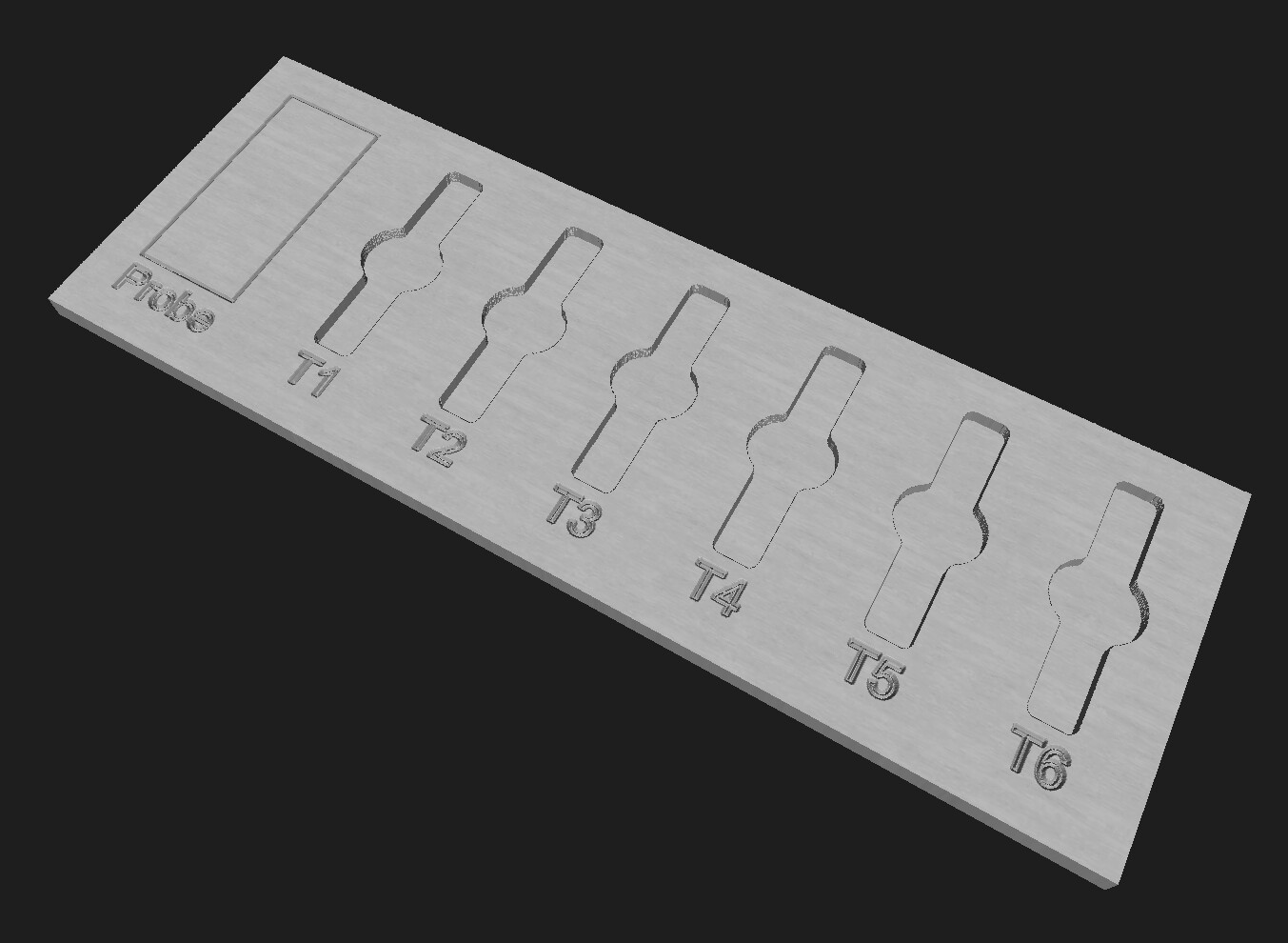
Picture that in your spoilboard. It would go something like this:

  1. Place the tools as defined in CAM in their appropriate slots.
  2. Run the job.
  3. For now, let’s assume we installed the first tool T1 and probed to set Z. I haven’t sorted out the starting tool details in my head yet.
  4. Run the job.
  5. It gets to a tool change and calls M6 T2. That triggers the M6 macro to run. It does the following:
  • Stores the current position
  • It sees that we haven’t gotten an offset for the “probe” section in the pretend magazine yet, so it moves to the probe position and pauses. You attach the probe and resume. You probe and it pauses. You remove the probe. This won’t be necessary for any more tool changes.
  • Moves to the position in the pretend ATC magazine for T1 (currently empty) and pauses
  • You remove the tool, put it back in the slot, and resume. (In the spirit of the LR3 instructions, you should make robot noises while doing this)
  • It moves to the position of the tool it needs to change to and pauses
  • You add the new tool and resume (more robot noises)
  • It moves to the probe section and pauses.
  • You attach the probe and resume.
  • You probe and it pauses. It figures out the new Z based on the offset it figured out for the first tool.
  • You remove the probe and resume.
  • It moves back to the stored position and continues.

The idea here is that it should be intuitive. If it moves to an empty tool slot, it wants you to remove the current tool. If it moves to a non-empty tool slot, it wants you to add that tool. If it moves to the probe position, it wants you to probe.

It would be nice if the pretend magazine area also included a button for resuming. Or even have a display to show messages.

How far have I gotten with this?

Not far. But, I do have M6 macros set up on my pen plotter that does automatic pen changes so I at least have some idea what that part looks like.

I did create a config and verify that I can get M6 macros to run even though I don’t have a spindle. It required me to add a spindle section. Trying to put “m6_macro” under “NoSpindle” didn’t work. So, it is tied to a pin that’s not hooked to anything:

pwm:
  output_pin: gpio.27
  pwm_hz: 50
  m6_macro: $SD/Run=_m6.gcode

I just moved my LR3 out to my new workshop finally. I’m looking to build a new (smaller) table and upgrade to the LR4 so I’m just thinking through what I want to do.

Thoughts?

12 Likes

I think that this is a really cool idea.

Is the ATC magazine something that would be permanently mounted/carved on the spoilboard or would it be a plate that would be placed depending on the job?

Robot noises just makes stuff work better.

2 Likes

I was thinking it would be permanent. I suppose you could remove it and add it as needed. Whether it’s carved into the spoilboard or a plate of some kind wouldn’t really matter. It would be important that whenever it is used, it goes in the same position but doesn’t have to be super precise. It would have to be based on machine coordinates so zeroing XY doesn’t break it.

4 Likes

That is actually not a horrible idea. If you are doing other things while your robot is working you can lose track of what tool is next.

I give it a double thumbs up :+1: :+1:

6 Likes

Wow!!! I am so glad i found this forum so long ago!!! The brilliance here is amazing!

2 Likes

Cool idea. It’s nice to have the manual tool change always happen in a convenient location, too.

I do a very limited subset of this with my LightBurn proxy for changing between laser and pen/marker where I stow or un-stow the pen up or down to switch between pen and laser for different LightBurn layers. I have it move to one position for pen down and another different position for pen up. While the idea was to eventually mechanically exchange pen tools in different positions, just having it move to a different position avoids questions of “did I already stow/un-stow the pen and just haven’t hit continue?”. While the proxy prompts for what to do, it saves some time walking back and forth from where I can reach the tool change location and where I keep the controls and proxy.

2 Likes

Ok this sounds like a real good idea to me. Like Ryan said, its easy to loose track of what tool is next if you have more than one tool change. And if you change to the wrong tool you trash the job more than likely. Having it always check for the offset is a great idea too. Bits don’t stay tight in the collet when its not attached to the router/spindle, so they often move around a little bit. Sounds like a bunch of great ideas and I am excited to see how it plays out!

3 Likes

Great idea, following with interest.

4 Likes

Awesome idea! I’ve had a thought about ATC but that is all it was …. a thought.

When this gets figured out then we can figure out how to do the offset if a diamond bit engraver is the tool. But that’s for another thought :wink:

What if we had a tap pad for the fake ATC that was wired so it doesnt require a clip on the bit? Im thinking a springboard the bit can press so no clamps required. Hasn’t someone already made one of these?

Yea, those are the tool length setters I mentioned before. I just don’t want to run the wire but that’s definitely an option.

2 Likes

I’d splice the wire to the z plate

I wonder if you could wire that to an IR emitter and put a small sensor on the core. Touches, emits IR, endstop triggers. Would be interesting to see if the precision could be good enough.

I’ve seen some people wire up the touch probe so there’s a jack or something on the core to plug it into. I wonder if something like that could be setup so you drive the core into something to connect it, probe, and then put it back. Something with magnets probably.

Tomorrow I’m going to see if I can get the M6 macros working for tool changes moving to the correct positions. To start, I’m going to let it probe back on the workpiece where it normally would so I don’t have to worry about Z offsets right away. For those offsets, I’m not sure if I should use G92 offsets or G43.1 tool length offsets. I imagine either would work.

I literally printed out my pretend magazine on paper for testing this out. The current size is 260x100 mm (about 10x4 in). Only about 30mm of Y needs to be in the working area.
pretend-atc

1 Like

You could put some sprung contacts on the outside of one of the YZ assemblies that connect to contacts connected to the tool length setter when moved into position over the setter.

1 Like

The pad needs to set an offset from a known probe height at the start of each job because the workpiece wont be the same every time… Need to set a variable to persist through the job to do this.

Is that already done or must it be figured out also?

Well, currently failing miserably. I can’t quite explain what the problem is. It seems like it might not like feed holds in the M6 macros? I can seem to do one but maybe it’s that it doesn’t like a feed hold inside an if statement. It seems like it goes so far and then it just exits the macro without completing the whole thing. I didn’t see any errors, even in debug mode, but maybe I don’t have something quite right.

I’m not sure. I’ll take a break and try again later.

I’d really like M6 macros to work so if the process needs to be tweaked, you don’t have to re-generate all the gcode. But if I have to, I can still do something with tool change gcode set in CAM.

I suppose if that calls gcode files instead, that could eliminate the potential gcode regeneration. Hmm, maybe even how it’s handled currently might make sense to put in separate files. The tool change gcode changed between LR3 and LR4 to increase the max probe distance from 80 to 110. So, gcode you generated for the LR3 might need to be tweaked for the LR4. Instead of hard coding it in CAM, it could just call a file to keep that independent. So, instead of that collection of lines, it calls $SD/Run=toolchange.gcode or something like that.

Well, at least thinking out loud here I came to the conclusion that I don’t really need M6 macros to work.

2 Likes

I don’t know if this will be helpful at all, but for many years my main 3D printer was a Jubilee Toolchanger. At a high level, when a tool change was triggered it used 3 files:

  • T0pre.gcode
  • T0free.gcode
  • T0post.gcode
  • T1pre.gcode
  • T1free.gcode
  • T1post.gcode

The pre included any things done before the actual tool change (I never used this much). This could be a purge, change to a working temp, etc.

The tool change information is found in the post files. This included the location to approach the lock point, and the moves to then reach the lock point, which were different for each tool. (Generally didn’t want to have the tool drag across the other tool locations due to collisions.) Once tool was clear and in the safe operating area, I moved it to a “pebble” device and extruded some plastic, then a servo knocked the pellet off the end and it dragged a brush as it went to start printing. All of this could be in a separate macro since once the tool was “safe” the moves were common.

The free files contained the relevant information for the approach to drop off. It also included holding temps, etc.

Each of those called the relevant macros “tool_lock.g” and “tool_unlock.g” since those were actually operating the REL (remote elastic lock) mechanism and taking feedback from a different end stop to determine when the tool was locked sufficiently tight. They were tool independent.

So a tool change actually called the pre file for the next tool, free file for the current tool and then finally the post file for the next tool.

In reading your thought process, I think you’re heading in the right direction. You seem to be thinking like a toolchanger now.

This was all on RRF, which is completely different I understand. But from a tool changer standpoint I think it conveys the mindset.

2 Likes

You do your CAM from the table surface instead of the work surface. That part should be easy. Then the tool setter is at a known height from the table surface. It is an extra CAM step to account for raw material thickness, but pretty standard.

3 Likes

Watching with interest