I’m taking this conversation to a separate thread from the Jackpot V2 thread:
^^^Link to that thread is above^^^
In general I’ll start with what I want:
I want to have a USB cable connected to between the pc and the ESP32 that is (ALWAYS) connected
I want to install a power blocker dongle to the USB cable going from the Mini pc to the ESP32 board so ONLY the Data wires in the USB cable are connected and the 5v wire in the USB cable is not connected
I want the ESP32 to be powered solely from the Jackpot board
I want the pc to recognize the ESP32 / Jackpot Com Port (even without the 5v wire of the USB cable live)
This is the setup I had with a previous V1 jackpot board and it ruled out human error since the order of operations for booting did not matter. IE: I could have the pc fired up and running (which meant the USB cable with Power Blocker) was not providing power to the ESP32/Jackpot and then I could boot the Jackpot up and never worry about voltage issues.
Currently my pc won’t recognize the com port or a com port is not established UNLESS i provide 5v current from the pc to the ESP32 through the USB cable.
In general I am hoping that the power suppled to the ESSP32 from the jackpot is sufficient to powerup the ESP32 and allow it to create a com port through the USB cable (without a 5v wire)
I’m running out of time for my day, but some next steps:
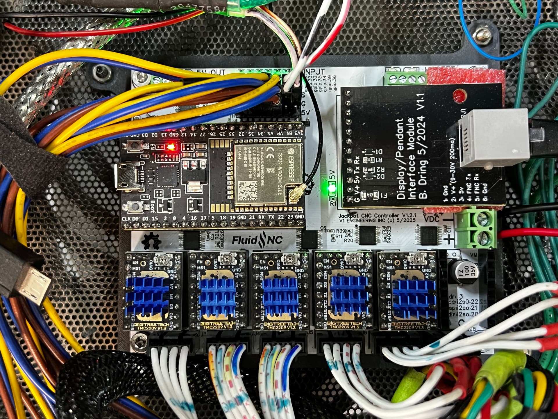
Power up the jackpot from VMOT power. Take a picture of the jackpot showing your wiring and state of all the LEDs.
Since you have a PC and you didn’t say Linux, I’ll assume you have windows.
Power off the jackpot.
Open up device manager on Windows. Look for COM ports and note what COM ports are present.
Power up the Jackpot. On device manager, once again note what COM ports are present.
If a new COM port didn’t show up, did a new unknown device show up?
What we do next depends partly on those results. It may be tomorrow morning US Mountain time before I respond- but I will respond.
I have a (work) deadline for Monday, and it’s Sunday, and since I’m a one-man shop…you guessed it, I’ve been selected to work on Sunday to get it done.
Next week, I plan to bring the old V1 board and the Old ESP32 back out to the Robot and perform some debugging to determine what’s going on.
In general, there are (5) hardware items that can make up a (mix)
V1 Jackpot board
V1.2.1 Jackpot board
Original ESP32 (assumed fried)
New ESP32 (remote antenna) Working
USB powerblocker Dongle
As I mentioned, when I combine 1, 3, & 5, I get a COM port on the PC (I’ll document what COM Port)
When I combine 2, 4, & 5 NO COM port
I want to see if there is another combination of hardware that gets me a COM port using the blocker IE:
2, 3, & 5
or
1, 4, & 5
You can assume that I will have the Jackpot powered up correctly (pictures to follow)
OK, here is a video demonstrating the difference between the OLD v1 Jackpot and the NEW V1.2.1 Jackpot
Essentially:
On the OLD setup V1, I get a COM3 port when the Jackpot powers the ESP32 using a power blocker USB…
&
On the new setup, V1.2.1 if I have a NON POWERED USB cable with power to the ESP from the Jackpot, I DO NOT get a COM port
As I mentioned, my solution is to use a USB cable with On/Off switch and ONLY turn it on when I need to or want to use G-Sender and ONLY after booting with the power from the Jackpot first.
Anyway, I could do more testing if anyone thought it would help:
I had this on the V1 board too and it was working fine until I fried the ESP32.
anyway I just wanted to add that bit of information in case it was helpful.
One other possibility is that these stepper drivers are new and came with the V1.2.1 board and I left the OLD stepper drivers on the Old board.
Wondering if for some reason the NEW ESP32 is not getting enough volts to make the USB port create the COM link with a data only USB cable. <<<Is there a way to check this with a multimeter to see if there is a difference between the Old V1 board and the new V1.2.2 board?
I may not have fallen into the rabbit hole, but let’s just say I can smell carrots!
Here is my plan:
Answer Jim’s questions
Plug the OLD ESP32 into the NEW Jackpot V1.2.1. Check for COM port with data only USB
Plug the New ESP32 into the OLD Jackpot V1 check for COM port with Data Only USB
Plug a (different) V1 Engineering ESP32 board into (Old v1 and New V1.2.2 Jackpot and check for COM port with data only USB cable
The above assumes there are
constants:
(PC, Power Blocker, USB cable, 24v VMOT power to Jackpot)
and
variables
(ESP32 board and Jackpot Board)
Based on the results, I’m hoping I can verify if I should focus on the Jackpot board or the ESP32
IE, if another combination of ESP32 and new V1.2.1 Jackpot gives a COM port as expected, then the issue may be in the currently in use ESP32 with the remote antenna
Also, if the combination of OLD ESP#2 and NEW V1.2.1 Jackpot gives a COM port with Data Only USB again, this would suggest the currently in use ESP32 is the issue.
However, if all variations involving the new V1.2.1 Jackpot yield no COM port with data only via USB, then the issue might be with the Jackpot.
Yes, it’s an M5 Fluiddial using Barts RJ12 connector at both ends
The Proximity sensors are just acting as limit switches with x1, x2, y1, y2, and z connected to the standard GPIO pins on the jackpot using Signal and Ground…I just added the pin in each row to send 5V signal to each prox sensor for them to function correctly. They are NC (Normally Closed) sensors see this photo for wiring:
<<<Note this wiring and these sensors were connected and working properly with the V1 board, so they have not changed>>>
I don’t want to go swapping out old steppers for new steppers etc. so we’ll leave that out of the equation for now
I checked the voltage on the new v1.2.1 board with the new ESP32 (remote antenna)
4.86 volts at the 5V pin
3.28 volts at the 3.3 V pin
Now, to run through the variable combinations of Jackpot and ESP32 to see if there is a repeatable “issue” with one of the variables.
As Jim has noted, this is not a “big issue” nor is it something that is happening to lots of users, so it’s more of an itch that I’m willing to scratch for a while.
In the end, the workaround is simple. The solution of using an ON/OFF switch on the USB cable means that when it’s OFF, there is no potential for having power to the USB before starting up the Jackpot. I’ll just need to get in the habit of switching the cable on if I plan to use G-Sender, which is likely a good thing to have in my workflow anyway.
Essentially, it’s a dongle that disables the 5V power pin in USB-A connectors, only allowing the Data and Ground pins to be active…Thus creating a Data-Only USB coable.
OK. Having you up and running is the main objective- and it sounds like you’re there.
Up in the pendant thread or this one, have you linked the specific data blocker dongle and power switch USB cable you’re using? I may grab those to experiment with.
Sometime this week I’ll do some more testing to see if I can find a way to recreate any of this.
Also, about this:
Those may appear to “act” as NC switches, but they are not. They are semiconductor devices and that means there’s potential system impacts even if they otherwise seem to work correctly. Mainly, there’s likely leakage currents and that can have implications at boot.
On your pendant setup, did you wire the M5 Dial to use VMOT or Jackpot 5V power? M5s can use VMOT or 5V, while CYDs can only use 5V. There’s potentially a lot of 5V power hanging off of that Jackpot.