Here begins my MPCNC build journey.
I am building a new Primo MPCNC that is feasible to put in and out of my car boot and take to makerspaces. So weight and size are key constraints. I already have a Handibot, which is a portable CNC with excellent rigidity, but with a 150x200mm work area. I am keen on cutting larger projects like signs. The Handibot can do it with tiling, but it is tedious. I have decided on a 1’x2’ workspace for my MPCNC so that I can work with cut-up eighths of a full sheet of plywood. Using the calculator on this website, that means the base will be 700x1000mm (so nothing sticks out past the edges). I am building a 7cm thick torsion box out of 9mm plywood. Ideally that would be lightweight plywood (all poplar) but I can’t seem to source that in Ireland right now. So I am using the standard “exterior hardwood-faced” 9mm ply available everywhere here. It is 543 kg/m^3 and birch plywood is 680 kg/m^3 for comparison. All-poplar plywood is about 400kg/m^3. A 700x1000mm sheet of 18mm birch weighs just about the same as my torsion box (10kg), but is substantially less stiff and would be more prone to warping. If you are interested, here is a gallery of photos of the TORSION BOX BUILD. https://photos.app.goo.gl/ZWxmE8YbjULs4EwB7
Click on the i with a circle around it for captions.
I got lovely strong polished stainless 25mm steel tubing with 2mm wall thickness (used for handrails) from Germany for a good price, 120 euros delivered. I plan to have the leg pieces extend into the torsion box, where I have glued blocks of birch plywood in the corners to drill 25mm holes into. I am imagining some helper of mine lifting the CNC up by the rails at some point, so I plan to reinforce the 3D printed parts in the corners somehow.
I am not sure how I will keep the leg pipes from slipping up and down, other than the 3D printed friction clamp that is part of the Primo design.
Ideas? I could drill holes in the ends of the leg pipes and insert long bolts through the wood and the pipes to lock them solidly. It would be good not to rely on friction. Adding up the weights of all the components, I estimate it will be 25-30kg or 50-60 lbs total, about as much as I can easily lift. I will have all the electronics and cooling in a separate box, not mounted to the CNC platform.
I am waiting for delivery of my Prusa MK3 printer. I will build a full enclosure out of LAK tables to allow heated building with carbon-fiber ABS filament. This filament should survive the heat of a closed car in the sun, which will be a common occurrence on my maker excursions around Ireland.
Is anyone else using a 1.5kW water-cooled spindle on MPCNC? It is 3.2kg (65mm diam), a bit heavier than my DeWalt palm router in the Handibot, and I am worried that the spindle carriage will need some re-designing. I chose this spindle because it is quiet. The Dewalt (or any brushed and air cooled router) would wake the dead. Being able to keep teaching my students while a job is cutting is important.
I got my build hardware from V1 engineering quickly (thanks Ryan!). Other components are slowly making their way to my doorstep…
Wow, you are going to build it. I see projects get explored on this forum, but I have the sense they never get built. After you use it for a little while, please post back on the forum and let us know how it is working for you.
I am building a 7cm thick torsion box
Not sure if it is a good solution or not, but my first though would have been to use aluminum extrusions for the base.
I am imagining some helper of mine lifting the CNC up by the rails at some point
You can mitigate the chance someone will make this error if you mount handles on the base just for lifting.
I am not sure how I will keep the leg pipes from slipping up and down
Not sure it is any better than a bolt through the leg, but the following occurs to me:
If you have access to the interior of the torsion box, a hose clamp will keep the pipe from slipping up.
A 3D printed sleeve that covers the entire exposed portion of the leg will keep the leg from slipping down.
If you are redesigning the feet anyway, include a horizontal hole that can be used to bolt the pipe to the feet.
building with carbon-fiber ABS filament
In my printing with ABS, I see significant shrinkage, so I’d do a bunch of test prints before printing the final parts.
Yes! Thanks to your and others’ advice in the LR2 forum to my post about TRANSportable CNC, I have a plan.
I think that aluminum extrusions would be a fine substrate, not susceptible to moisture absorption but perhaps thermal expansion. But certainly extrusions are more expensive than plywood and glue, after adding all the brackets and bolts, and maybe heavier. I will do a stress/strain test once my torsion box is all built and post here how much it flexes under load compared to 18mm birch plywood. If you have any extrusions that you can easily do some measurements of deflection under load, that would be helpful for comparison.
The inside of the box is now being sprayed with acrylic lacquer to reduce humidity warping effects. I will then also seal the outside with lacquer after final assembly and sanding.
Handles: yes. I already got them.
The hose clamp idea is a good one. I got some carbide tipped drill bits today, so it will depend on how difficult this 2mm thick stainless tubing is to drill. I may just screw the end panels of the box on rather than glueing so that I can have access to the legs in there.
Printing CF ABS: yes, there will be lots of trials and tests and calibrations first, as I have not much experience with 3D printing and will be using a home-built Prusa MK3 kit I am eagerly waiting for. I have watched enough YouTubers now to know that it requires a temperature-controlled warm enclosure. I welcome all tips if you have printed with carbon-fiber ABS.
The quality of your carbide bits will make a huge difference when drilling stainless steel. I’ve had carbide drill bits that dulled to unusable on the first hole, and other that passed through easily and showed little dulling.
Just so you know, this is not as rigid as PLA, you are building a smaller sized machine though so maybe that will make up for it, but not sure. Just warning you that it could result in greater deflection while milling.
Never been to Ireland (yet ) but unless you are expecting it to get above 110F regularly, i would stick with PLA. Also throwing a blanket over it will help it keep cooler then the rest of your car.
I am going to use carbon-fiber filled ABS, which is at least twice as stiff as plain ABS and stiffer than PLA (see this table)
Although it does not get very warm in Ireland, inside my car it does, if the sun is shining on its black roof. I often go for hikes on my excursions and leave it in the sun for hours. PLA does not survive in hot cars without deforming. I would hate to ruin weeks of building effort and expense in one hot day.
PLA also does not survive a washing machine on 30°C without bending. You can ask my wife who put a boat I printed in there by accident. I do not plan on washing my MPCNC though.
give it a shot and see how it works. Then let us know… but I would say if the chart is wrong about the working temp, then it could be wrong about the rigidity. Seems like the chart is assuming cf pla witch is why it states such a high rigidity and low temp tolerance. And in general I would think both depend largely on the exact formula of cf filament used. I don’t recall anyone using cf filament(though I think some have mentioned wanting to try it). I hope the prices on it are cheaper there then it is here, and I wish you the best of luck with it. Just wanted to make sure you know you are venturing into the unknown. I can’t wait to see how it turns out.
Thanks, Atom! Yes, I think you are right that the chart is assuming CF PLA. I think for something that is likely to get banged around a lot by moving it (my 1000x700mm transportable CNC), toughness is more important than rigidity, which usually comes with brittleness. I am still waiting for my 3D printer and (very expensive) Kimla CF ABS filament rolls. So stay tuned for the comparison with PLA in terms of rigidity and brittleness. If it turns out to be too flexible, I can add flying buttresses to the legs and center supports to the rails. Which parts of the MPCNC influence its accuracy the most? (where is flexing the biggest problem?)
I finished the Torsion Box Base while waiting for: The Next big chapter on this Portable Primo build: I finally got my Prusa i3 MK3S+ printer, 8 weeks after ordering it. Making the MPCNC was a great excuse to get my own 3D printer, and a good way to burn up my tax return. I have used them in my research lab and makerspaces. But now I can goof around with my own. Here are photos of the building and testing of the 3D printer: https://photos.app.goo.gl/E9MR4n5maUG8Dcd3A
(Feel free to add your comments and suggestions to the photo captions. Click on the i with a circle around it in Google Photos)
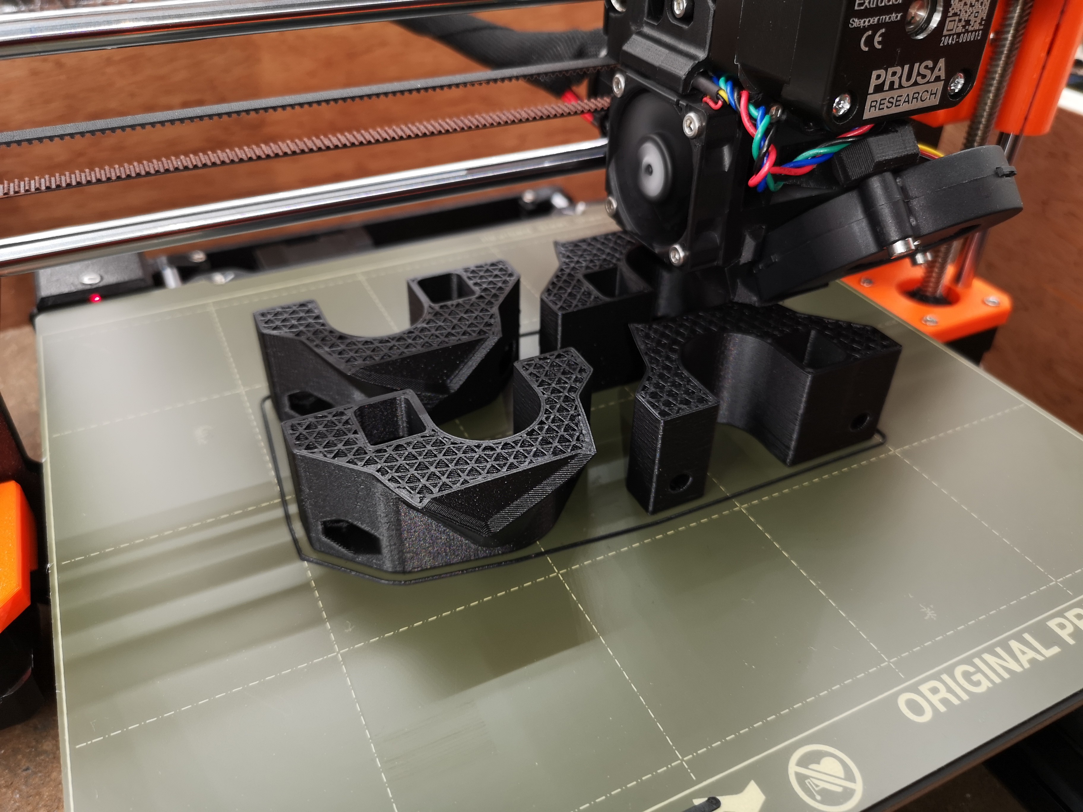
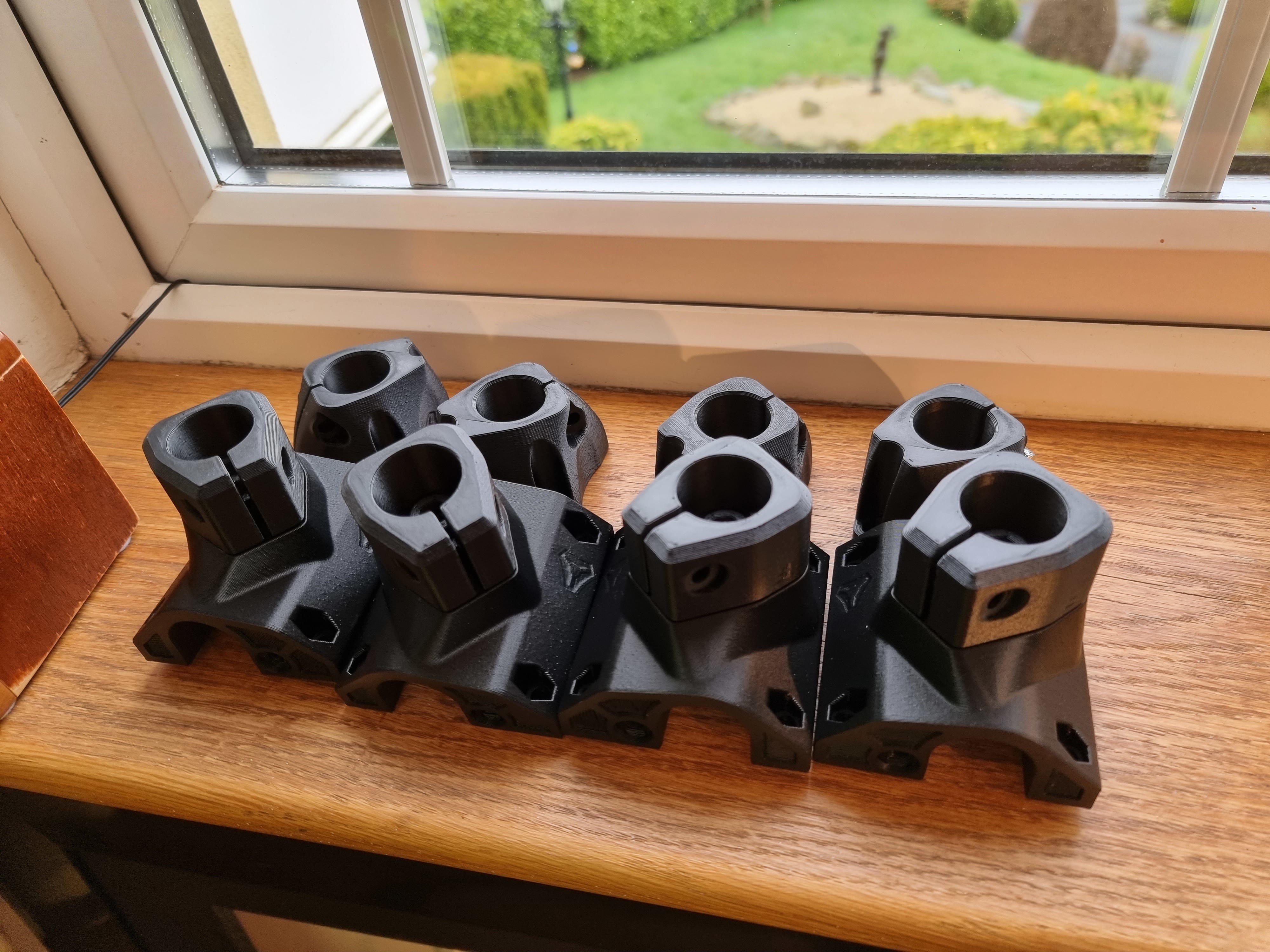
I will be making the MPCNC parts out of 20% carbon-filled ABS for portability-toughness and resistance to warping in a hot car. I am happy to say that I have successfully printed the Prusa extruder’s parts in CF-ABS and can report that it is plenty stiff and strong enough for the MPCNC. Even with only 20% infill. Kimya CF-ABS is not cheap, though, about 58 euros per 500g spool.
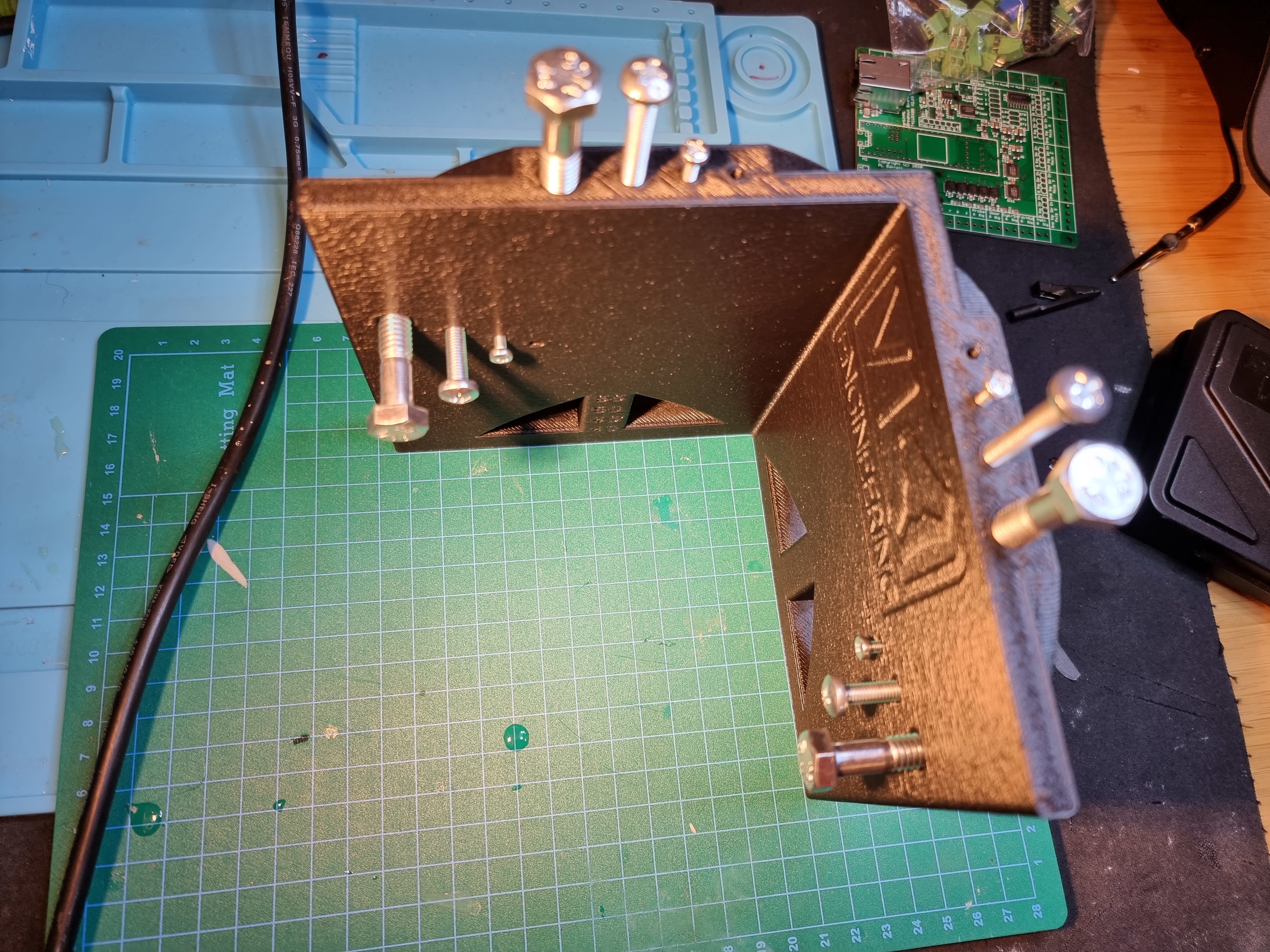
I have also made substantial progress on a portable controller box, to be described in the next chapter when it is finished.
How exciting! I printed my first parts for the MPCNC today!!
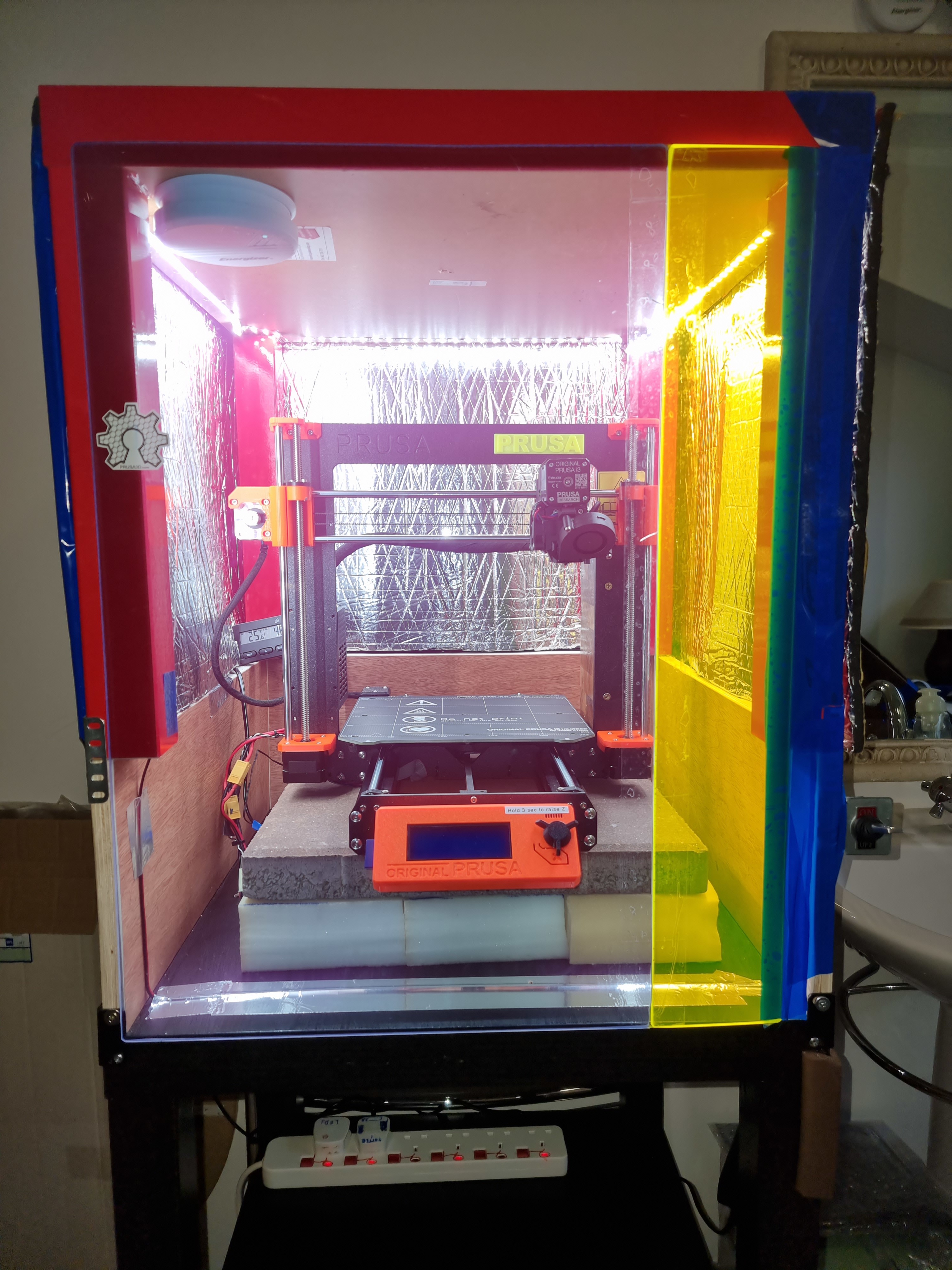
Here are details of the enclosure I built to keep the temperature stable around 42C while printing CF-ABS.
(You can see my captions if you click on the i with a circle around it when you expand any image) https://photos.app.goo.gl/dgkFbcPw2GD8GWEU8
I see you moved the power supply out of the enclosure, I assume the steppers and control board are housed in that same box(sorry not familiar with prusa’s layout)? I only ask because 42C Is a pretty high ambient operating temp for most electronics. If your screen is powered while your printing you may want to move that out of the enclosure as well or it may have a reduced life span.
That said it is really nifty! I have been considering doing somthing like that with my spare ender 3. I like the idea of using the granit slab for temp stabilization. I was thinking of using tightly packed sand.
Thanks, Atom. Another benefit of the heavy paver under the printer is that it is much quieter, but since mine is in a room by itself, that was not a concern for me. The Prusa Mk3S+ is very quiet already. Yes, I will probably move the LCD and controller out eventually; I will likely have to make longer cables. But in the original inspiration plans from Prusa, they did not move them outside, and some forum posts suggested those are more heat tolerant than the PSU.
There were a number of things I did not like about that Prusa enclosure plan. One is it is too short, with only two Lack tables. Another is that it was a re-working of a similar plan from before the Multi-Material Upgrade. I think it would have been better if they started fresh. So I did, with more headroom and no lifting lid, and plans to put all the spools below, not above the enclosure.
Their design has lots of plastic parts which is great if you love to 3D print things and have lots of time and spare filament. But I cut wood much faster than I print plastic right now and have lots of scraps.
Here is my progress so far…Corner tops are printing, 5 hours left.
I see, based on the directions you posted it still has the steppers and controller inside the enclosure. Your correct that the psu is the most susceptible to higher ambient temps because it produces the most heat. Similarly the next most susceptible components would be your stepper drivers and control board.
There are some differences between your build and the build posted, most significant is that yours actually has a heater and it’s placed under the printer. They are expecting case temps to rise slowly and for the air below the heat bed (where your electronics are) to be at least slightly cooler than the rest of the case for most if not all of the print time. I would not expect this to be the case with your build. This might not make a substantial diffrence depending on how well the electronics are cooled to start with.
My concerns:
Short term:
With your stepper drivers being inside the heated enclosure, and above the primary heat source, I would be concerned that they could overheat on long prints. This would cause them to turn off so they don’t become damaged (good for the printer). But when they turn off (potentially 24 hours into your 32 hour core print) it will cause your print to fail.
Long term:
It could shorten the life of your electronics if you print at those temps for long periods of time regularly.
I just wanted to warn you mostly about the potential for failed prints, I know the filament your using is expensive and I would hate for you to use half a roll on the core just to have It fail because your steppers overheated. But hopefully it’s not a problem