Thanks for the warnings, Atom. Duly noted. For these reasons, I did the long XYZ test print first to be sure that nothing overheated and monitored everything closely. I have had it running pretty much non-stop for several days now at 42C with no problems at all. The control electronics of the Pruas MK3 are in a vertically oriented box with lots of vent holes to the left rear, behind the vertical member, not under the heat bed. Only the Y stepper motor is under there.
Also, I am only turning on the turtle warmer beneath the paver when not printing, to keep the stone warmish (about 32C) so there will be less of a temperature change when I resume printing.
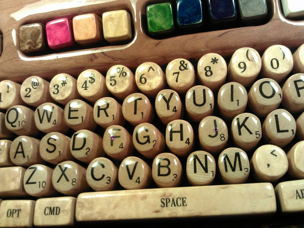
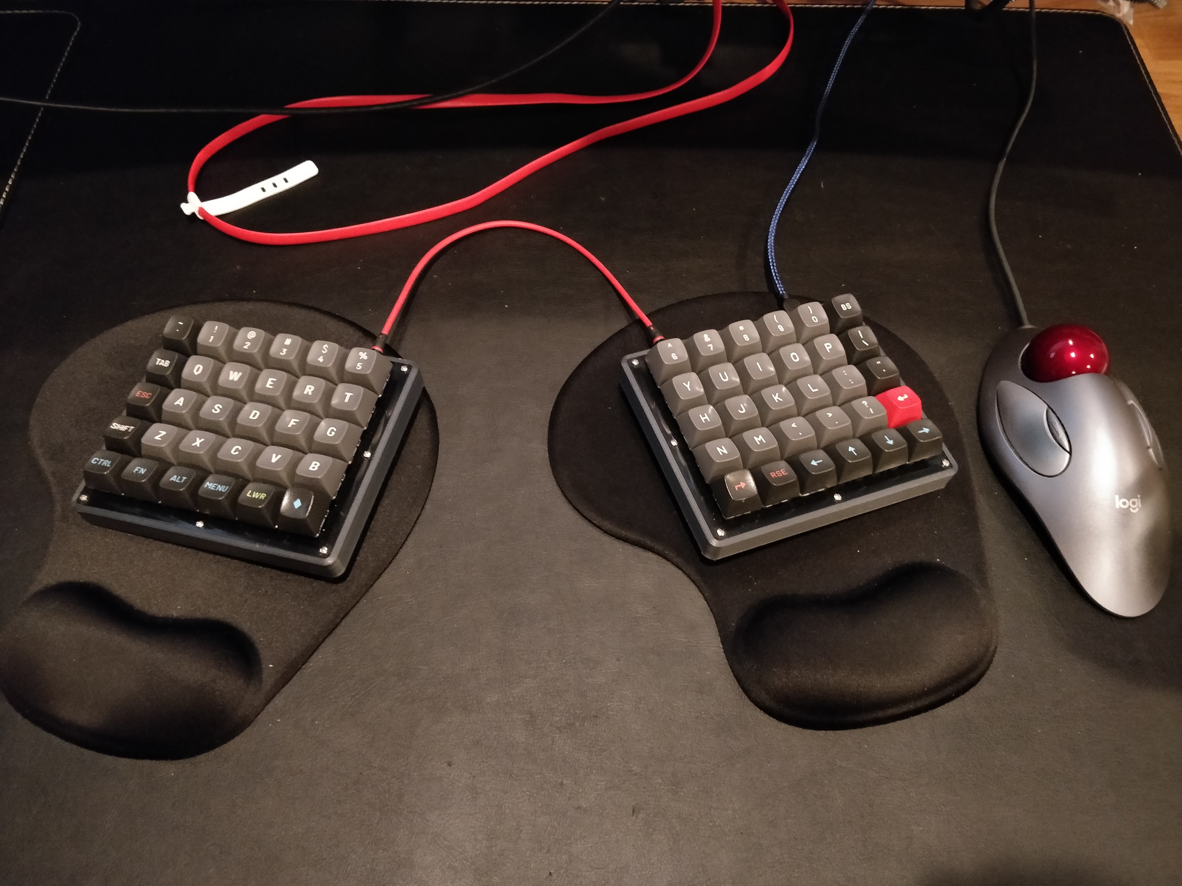
That’s awesome. I like the use of the resistor color code for the F keys. And you really did just completely wrap a whole keyboard in there. The cordless drill into a window opener is great too. I can’t wait to see what you do with a CNC machine.
I wonder how much easier it would be to make that keyboard with a cnc and 3dprinter… I feel like you could mill the body and keys, especially if you use the more modern mechanical key switches (though I understand why you chose the old IBM style. They where really a nice feeling keyboard but a bit too loud for me). I’m thinking using somthing like this https://www.thingiverse.com/thing:3478494 but making parts out of wood. What do you think?
Yes, I have often thought how much easier it would have been (and a lot less fiddling and adjustments) if I could have CNC’d the wooden keyboard. I had not done any CNC yet at that point, but knew from the things my grad students made in our shop what one can do with CNC. It also opens up the possibility for mass production. There are a lot more clicky keyboard enthusiasts out there now than when I made mine, coming up with such creative ideas. My good friend, Dr. Arno Klein, has recently used AI to come up with the most ergonomic arrangement of letters on a keyboard for whatever language you wish. If you are bothering to make your own keyboard, consider also learning a new key layout: https://www.preprints.org/manuscript/202103.0287/v1
Interesting stuff! but I think I will stick with qwerty. I have to use keyboards at to many different locations and switch back and forth will surely confuse me
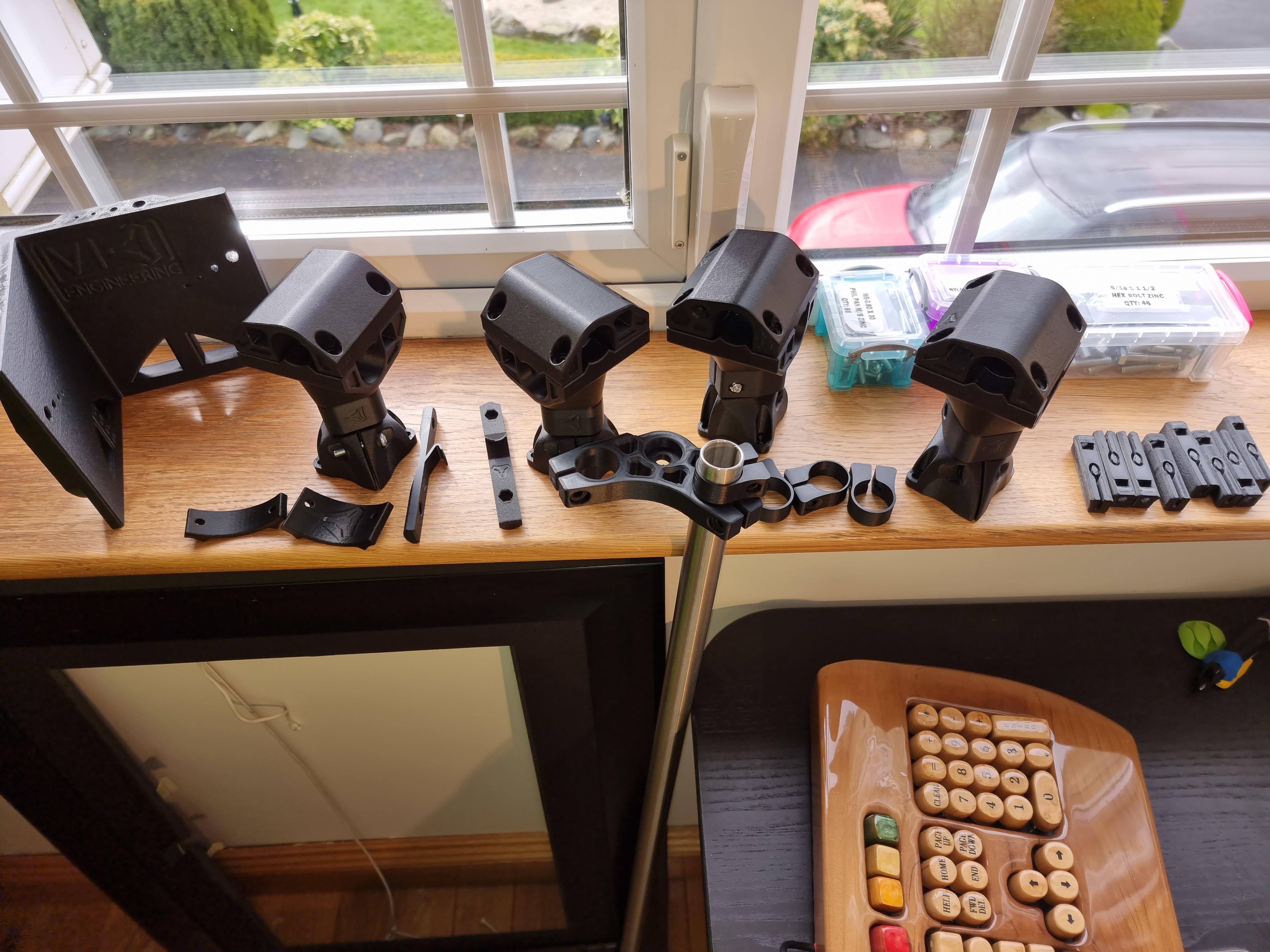
Here is my latest progress on the Portable Primo Build:
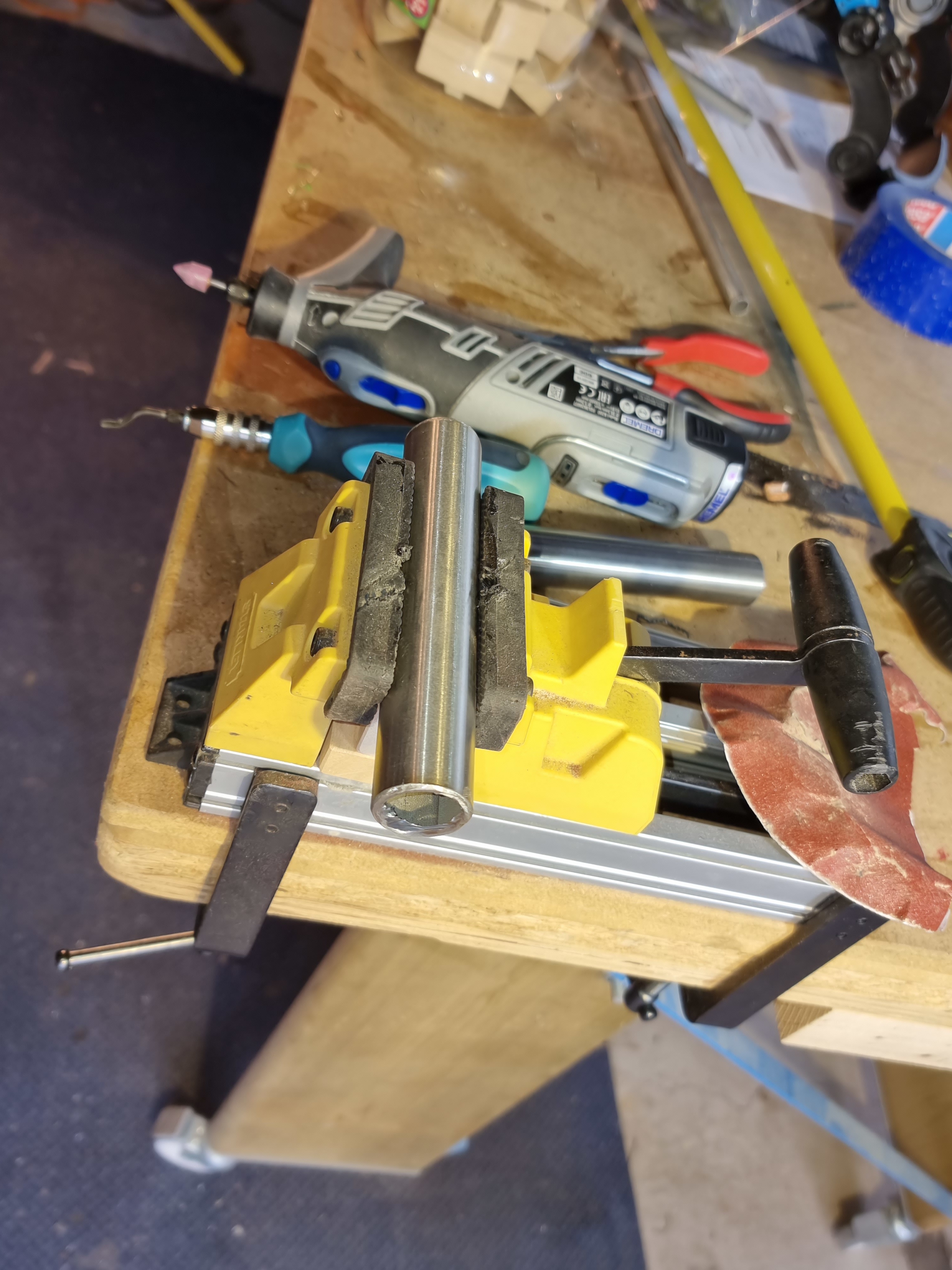
Yesterday and today I cut all the tubing to the right length, cleaned up all the flash, and drilled the holes. Do you guys have a good way of removing flash inside the tubing where the weld seam is?
Arno says:
"It can absolutely be tuned for a given spoken/written language. All one needs is bigram frequency data. If I were to redesign this layout specifically for use by programmers, I would go about it differently. Having said that, I tried to organize punctuation and symbolic characters used for programming in convenient places for when I program.
I had a much tougher time getting the thing all square than most of you because I have the legs going into tight-fitting holes in the torsion box, so I can’t shift them easily. I did have to shift one, due to a wandering drill bit. That was tricky! You can see all the latest photos of my build here:
It pretty much worked the first time!
I only had to edit and re-flash the firmware in order to get the logic of the Hall Effect switch endstops right. They are normally high, and go low when the magnet is near. I thought that is the same as what the mechanical microswitches do with C grounded and NC connected to a pulled-up signal line. Anyway, dual-endstop homing is working great. I have not done any drawings or racking adjustments yet.
First, I need to re-build the Z axis to accommodate my large spindle (65mm). The Makita mounts with the recommended holes set it way too low, eliminating most of my Z travel. I have re-drilled higher holes. And I am going to use two of the lower Makita mounts because the upper clamp gets in the way of its own screw holes.
At every turn I see clever design features. Thanks to Ryan and all of you who helped refine this design.
BIG NEWS! First drawing!
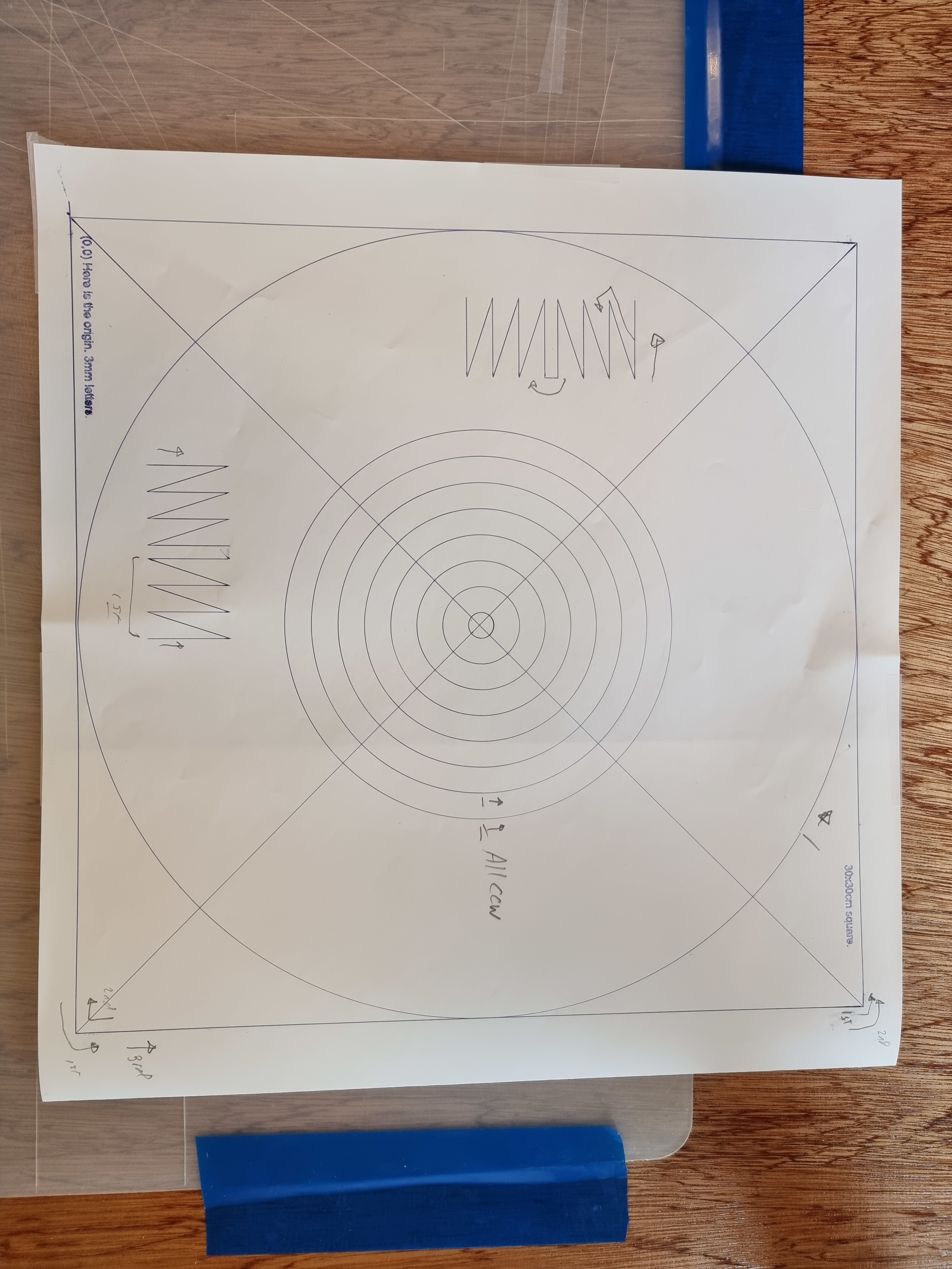
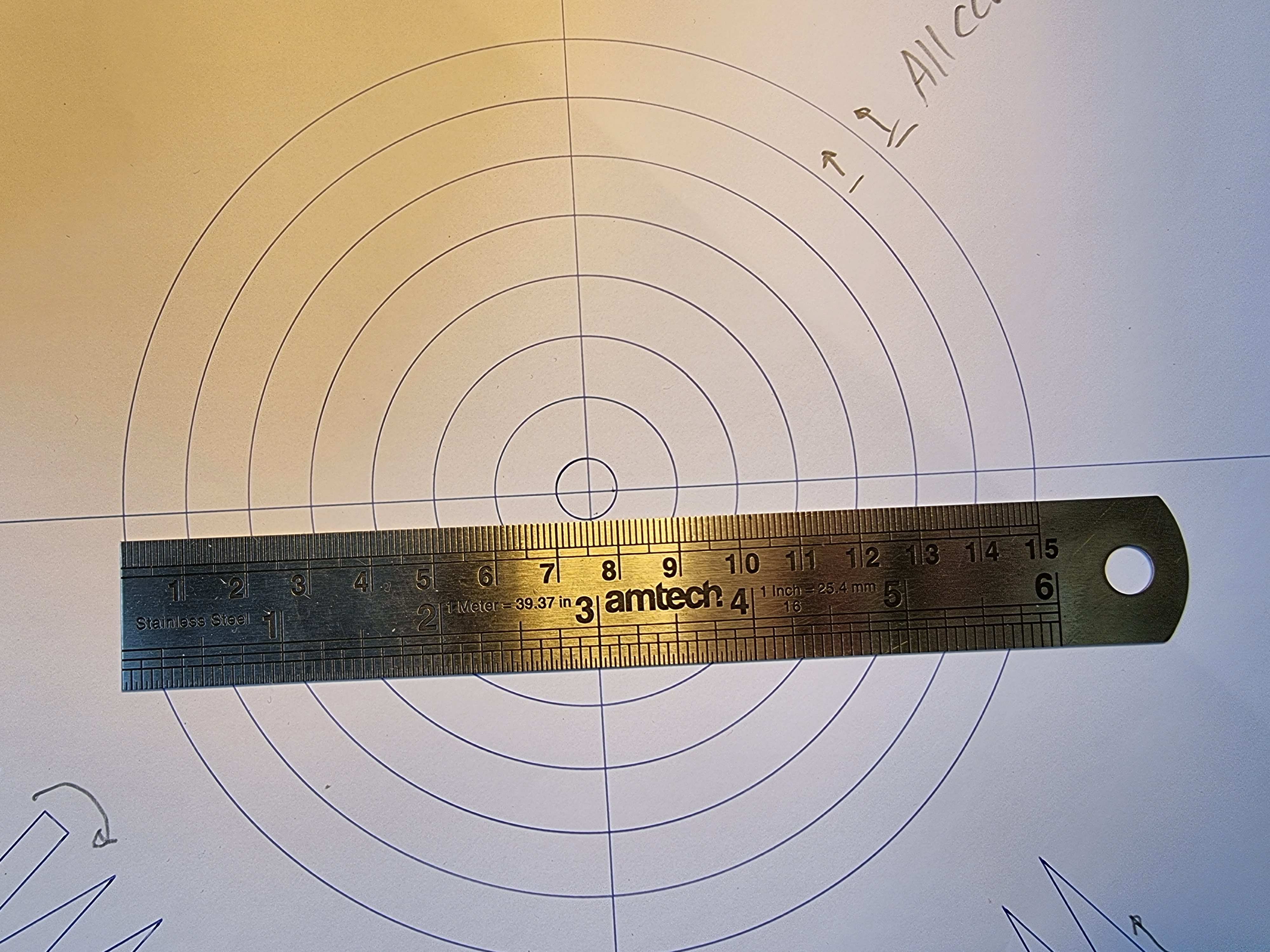
I have been working on the electronics and got the wiring to the point where I think it won’t catch fire, so it was time to test out the squareness of my Portable Primo. I am very pleasantly surprised how good it came out with no adjusting yet. I have dual endstops and set their positions to trigger at the same time when I push on the center of the gantry in question. I made a test pattern with a 30cm square and it is only off by less than 3mm (1%) comparing one diagonal to the other. Here are some photos.
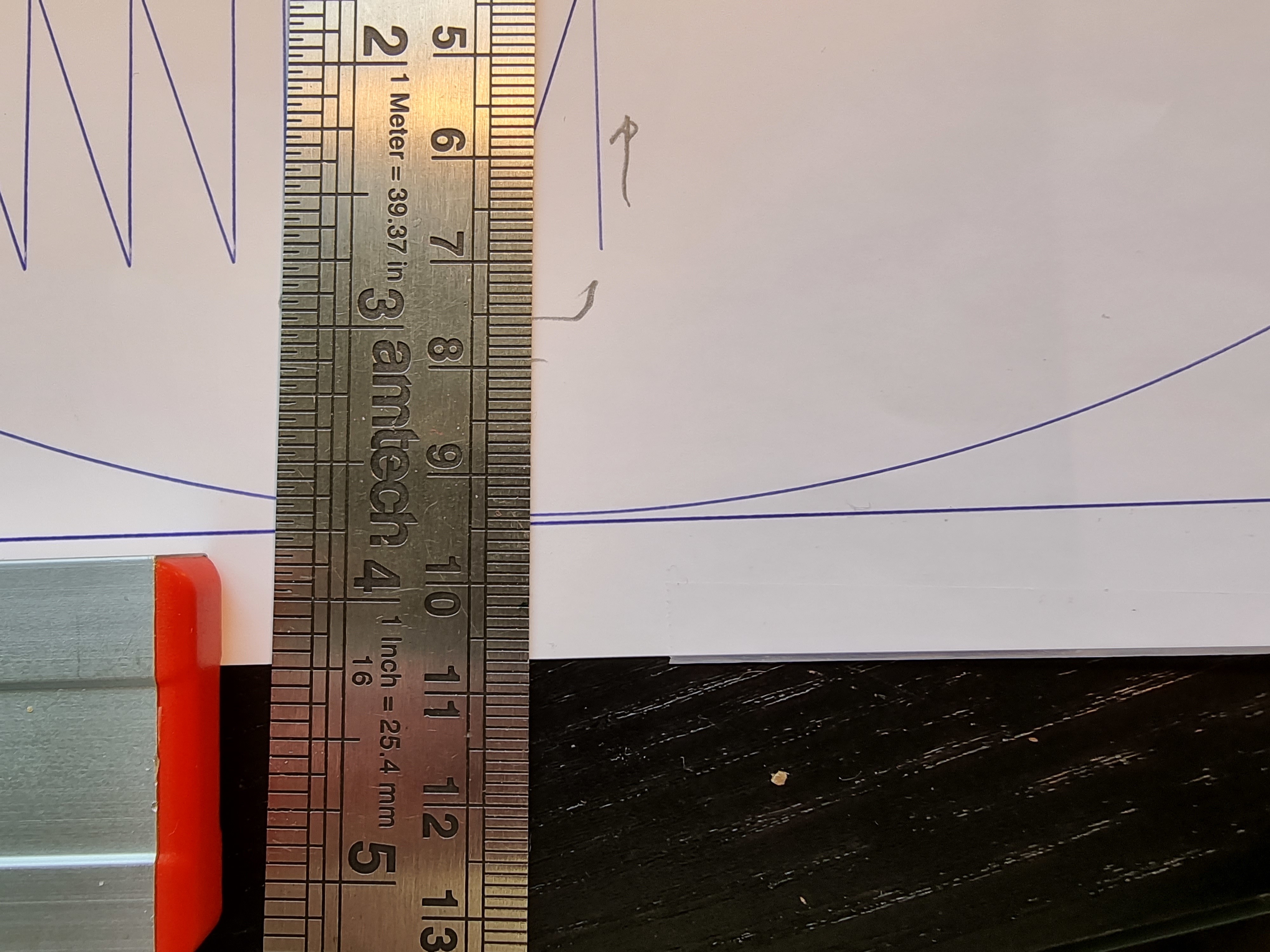
The Zig-zags are to check for backlash and I did not see any. Perhaps a better test for backlash was the tiny (3mm high) lettering: it drew the inside of the O one direction and the outside, the other, and they came out perfect.
I know there is a diagram somewhere but can’t find it. I usually just do a guess and check. Draw the square, check the diagonals, adjust one endstop and try again. If it gets better it is a little math to figure out the exact distance you need, if it is worse rest it and try the other one.
If your diagonals are off by 3mm I would adjust by half that as a quick and dirty.