If I understand the firmware correctly (which I am sure I don’t) I think the cleanest way to do this is to create a new state, like HOLD, but one that allows movement. Something like PAUSE_ALLOW_MOVEMENT. Sounds like another week of going down AI rabbit holes. First I need to decide which version to fork off of. I gotta say that my first venture into V4 did not go well. The changes were significant enough that I could not figure out where to make the necessary CORS mods to make it work with my UI. Has your work with FluidTouch required any of that or is it strictly Websockets?
Attached is the plan I had Claude Opus come up with yesterday after chewing on it awhile. The timing is wild. I was saving this for later after working through and testing my other changes.
plan-motionDuringFeedHold.prompt.md.zip (3.9 KB)
No, FluidTouch doesn’t have to worry about CORS. It’s just websockets. The new async web server has a CORS middleware instead. I didn’t test it other than that it compiles but I think these are the changes necessary:
jeyeager65/FluidNC at feature/cors
I haven’t really run into issues with FluidNC v4.0.2 yet. I know previous versions had a bunch of issues. I had to add an M61 to the M6 macro for my pen plotter, but that was due to a change in v3.9.5.
Also, note that in 4.0, you can have webpages load from the flash or SD card, and not just the index.html.gz. Before they downloaded but now they render in the browser.
http://fluidnc.local/flash/mycustomui.html
http://fluidnc.local/sd/mycustomui.html
I think I’m going to use 3.9.4 for the base and instead of modifying the FeedHold state, I’m going to create a new one called PAUSE…something. I’ll document all the changes for you and let you know how it goes, but I presume that the changes needed for 4.x will be significantly different. I just don’t trust V4 yet. I tried compiling the first V4 release and it wouldn’t work with either UI version. Wasted a day of my life. Finally, Mitch let me know that it was buggy and I should use the latest code. 
v4.0.2 is the first one that has a shot at being production ready but I’m still testing it. The earlier ones were not.
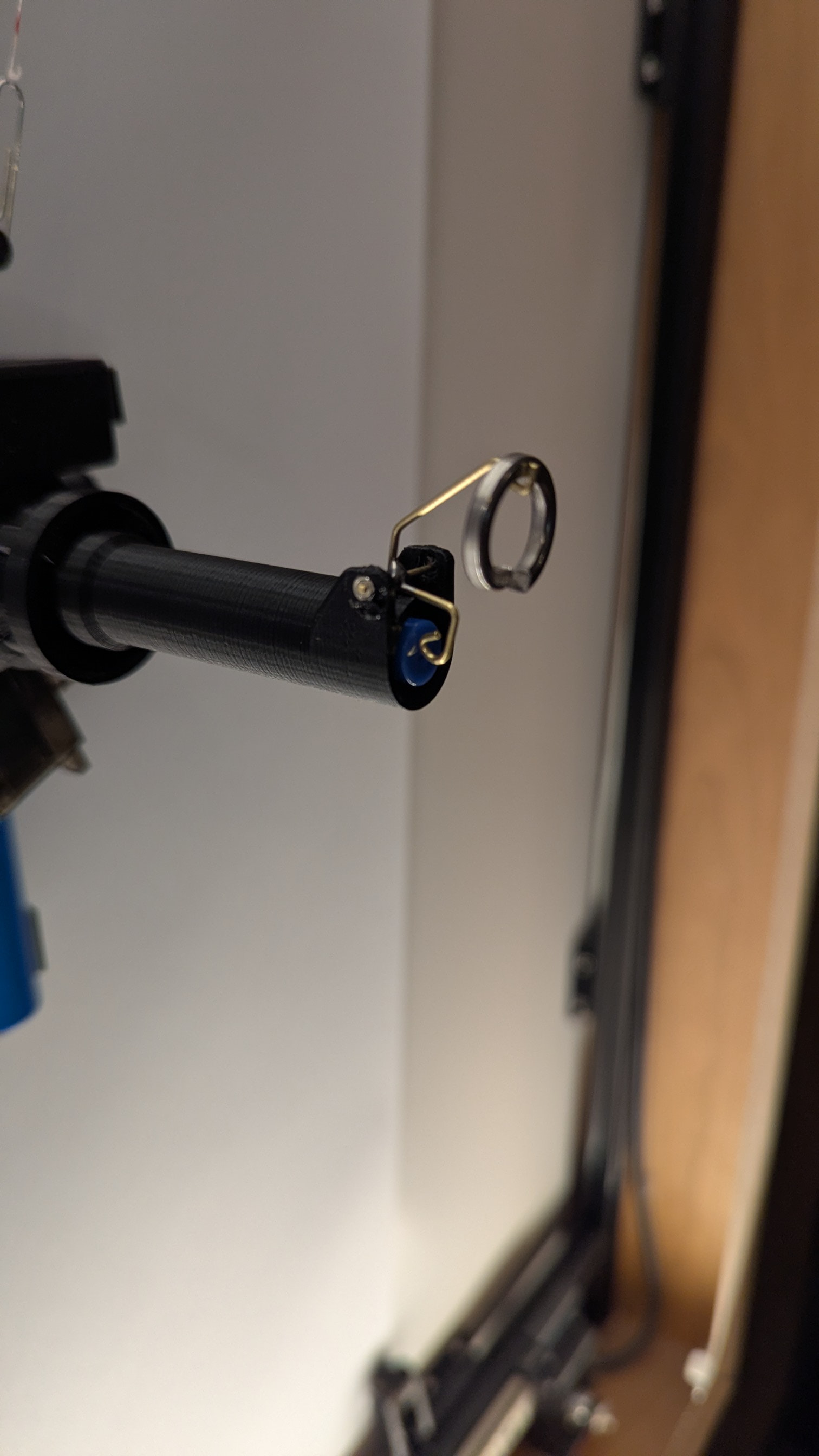
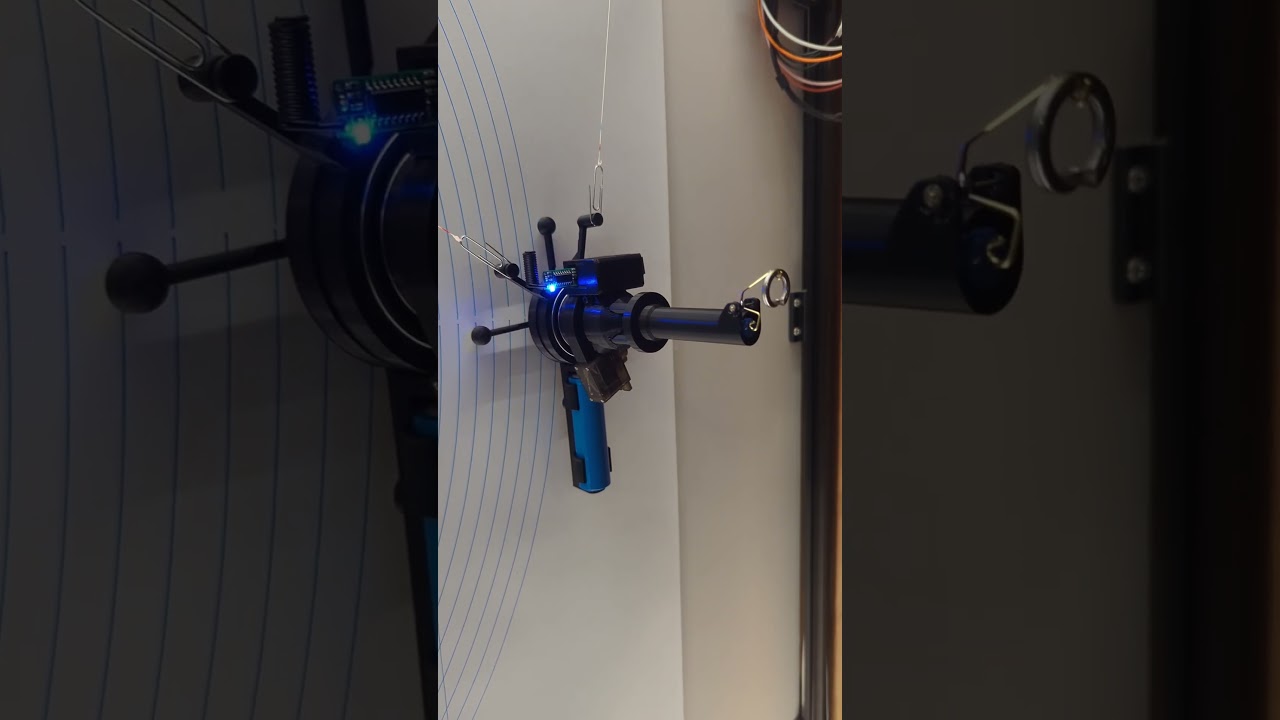
Jason,
How has Claude been working out for you? Does it send you down a lot of rabbit holes?
Claude has been working out fine for me. Sure it does dumb stuff sometimes. There is a learning curve to it. You definitely need to have some background knowledge in whatever you’re doing so you can redirect it before getting too far down a rabbit hole.
I thought I had things figured out but I guess I’ve been throwing softballs. I’ve bounced around, but I haven’t tried Claude yet for coding. Figuring out which AI to use seems to be just as difficult as figuring out how to best use them. Was using Copilot today and I think I’ve had enough of that. Among other things, it is fixated on some old repo of FluidNC that bdring still has on github. The config.yaml has a very different syntax now, so it is rife with bad info. No matter how many times I tell it to drop it, it keeps going back. And that’s just a minor frustration. I’m trying to fix some things in the WallPlotter kinematics section of the FluidNC firmware now and it is extremely frustrating. It says it can see the build I am using yet it just guesses when trying to fix bugs and add new features. Obviously the first thing it was taught was to compliment the user and make up excuses if asked why it is wrong so often.
From what I’ve read and experienced myself, for coding, Claude is in the lead. I usually use Claude Sonnet. I have used Claude Opus a couple times and it is better but that eats up tokens at 3x the rate.
Microsoft has made the term Copilot quite confusing. I use Claude via Github Copilot in Visual Studio Code, which lets you try a bunch of different models. Copilot built into Windows and generally Microsoft AI is pretty terrible.
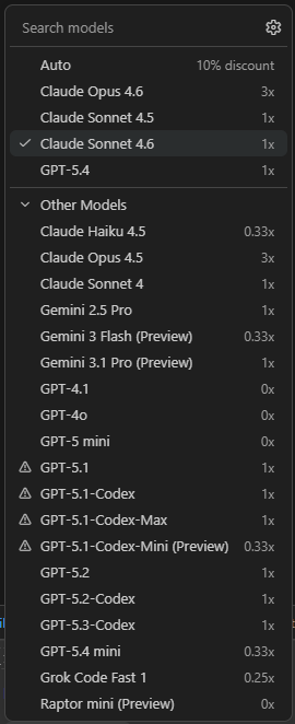
I assume with Claude that the token model is a pay as you go but if you shell out $20 per month you have access to the latest with no additional cost?
I’m using it via Github Copilot but you can also purchase it from Anthropic directly. I’m on the “Pro” plan which is $10/month which gets you a certain number of “premium” requests from agents like Claude. You can also setup a budget to let you go over and pay based on usage. I have had the “Pro+” plan a couple times which is $39/month but you get 5x the requests of “Pro” included.
GitHub Copilot · Your AI pair programmer
Anthropic has Claude plans at $20/month and up but it has some other features that way too. I haven’t quite figured it all out. In general, any paid monthly plan only has a certain amount of usage included.
GETTING THERE…
I thought I would share some insights before I started uploading 3d models, etc. I’m not planning on going into as much detail on this mod as I did on the original build. If you have any questions, just ask. If you are planning on making one of these, suggest you read this before you dive in.
Basics:
-
This is an add on to the frame of the Wall Mounted Pen Plotter. It doesn’t need any of the linear rails, motors, etc. from the original, just the 20x20 aluminum frame and the drawing surface. If you’re creative, you might not even need those.
-
Size is flexible. If you get the geometry settings (pulley locations, origin and drawing area) set correctly in the config.yaml, it should work with any custom size. The motor spools are designed to hold enough string for a canvas size of 765mm x 820mm. You might be able to fudge a little bigger, but if you want a significantly larger drawing area, you will need to print motor spools with more “threads”. A smaller canvas is not a problem.
Pens:
- I couldn’t get the ballpoints that I typically use to work with this. It simply doesn’t provide enough pressure for the ink to flow onto the paper. So, I designed it for the Pigma Microns which I use on the cartesian build. @orob did show some interest in making a dry erase version, so I will provide the model that accepts Expo Dry Erase markers (the Fine Point versions, not the fat ones). It will be untested, but it should work.
Options:
-
Wireless Pen Lift. You will be able to draw without adding this option. Many of these types of drawing machines out there have no pen lift. It obviously limits your drawing options but still works. The wireless pen lift will require some soldering skills and the ability to flash an ATtiny mcu. Technically you could make a much easier lift that has that ugly wire that drapes from the gondola over to the control board (like every other Polargraph I have come across), but there isn’t much challenge in that.
-
Homing. I don’t recommend this option unless you really want or need it. I didn’t come across any others out there that have the ability to home. The stock FluidNC firmware will not home a machine configured with “WallPlotter” kinematics. A modified version of the firmware is required. That should tell you something. If you have any questions about this, I would love to discuss it with you. I spent a week trying to understand it and figure out how to do it. I’m still working on it but am getting close.
FluidNC Firmware:
- WallPlotter Kinematics are not supported by the FluidNC project, but it is an option in the config, and I have been using it with very few problems so far. There is a very small paragraph in the Kinematics section of the Wiki that mentions it. So far, I have found one minor bug in the firmware that occurs when a “zero length” move is sent to the planner. I will provide a firmware build based on release 3.9.4 that fixes that bug as well as provides the ability to home.
Jackpot Controller:
- Should work fine with JP1 – JP3.
Build info to follow soon…
Cheers
The maslow works on the same principle (I have one as well) and it has been found to be optimal at 15 degrees off vertical for the router to have sufficient force to cut and low enough friction to move. Perhaps if you mounted the setup with a ball-point pen on an easel, it might work? Too bad your initial use setup didn’t work out like you hoped.
Thanks for sharing the process and the design! I’ll get on it hopefully soon.
i’ll look into how this works. I have an idea to try… perhaps coming to a thread near you.
It’s a common setup for pen plotters. They use a servo for Z. Connection is straight forward. Three wires from the servo to the controller: 5v, GND and the signal wire to a GPIO. The rest is done in the config.
For a wired connection, the gpio used for the servo signal is configured in the config.yaml to use PWM. FluidNC does all the magic. For my wireless, the 5v and GND come from the battery on the gondola. The gpio on the Jackpot is configured as a simple output pin (HIGH for pen up and LOW for down). That state is transmitted to the gondola. The ATtiny MCU on the gondola receives the HIGH/LOW state changes from the 433MHz receiver and does all the PWM magic (via one of its GPIOs) to move the servo that lifts and lowers the pen. Easy, peasy.
Build - Part I
Pulleys and Motor mounts
3d Models:
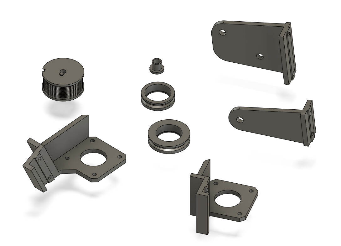
Here are the STL files:
frame_models.zip (364.6 KB)
Notes:
- I used 40lb braided fishing line for the string because it has little to no stretch. The pulleys are designed to use 8mm ID x 22mm OD x 7mm bearings and M6 x 20 button head socket cap screws with lock nuts.
- See pics for assembly and mounting. Take a close look at the pulley orientation. There is a back and a front to the wheels and the bushing needs to be inserted correctly as well.
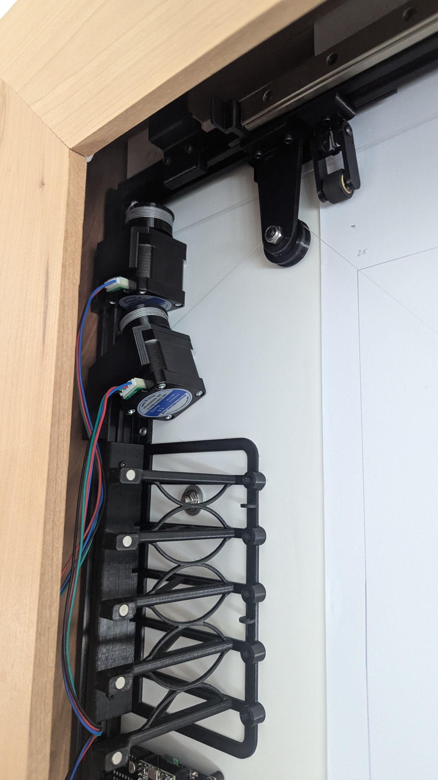
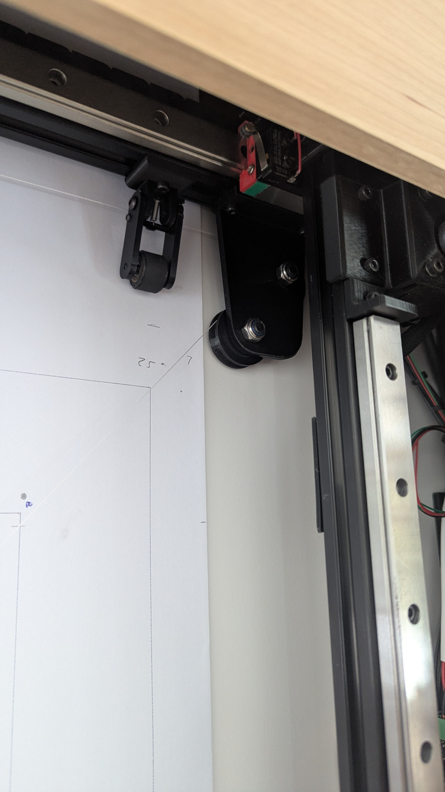
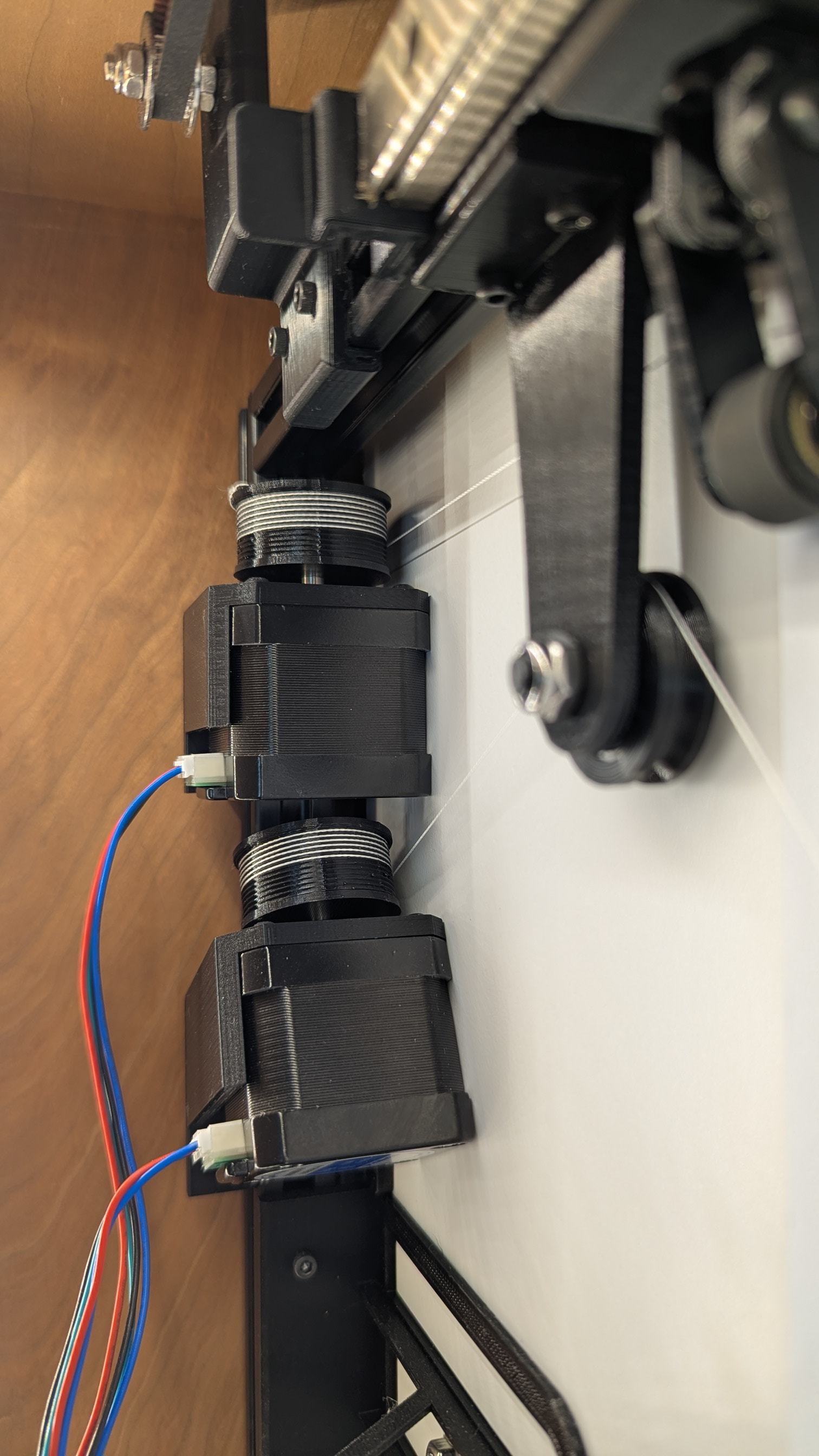
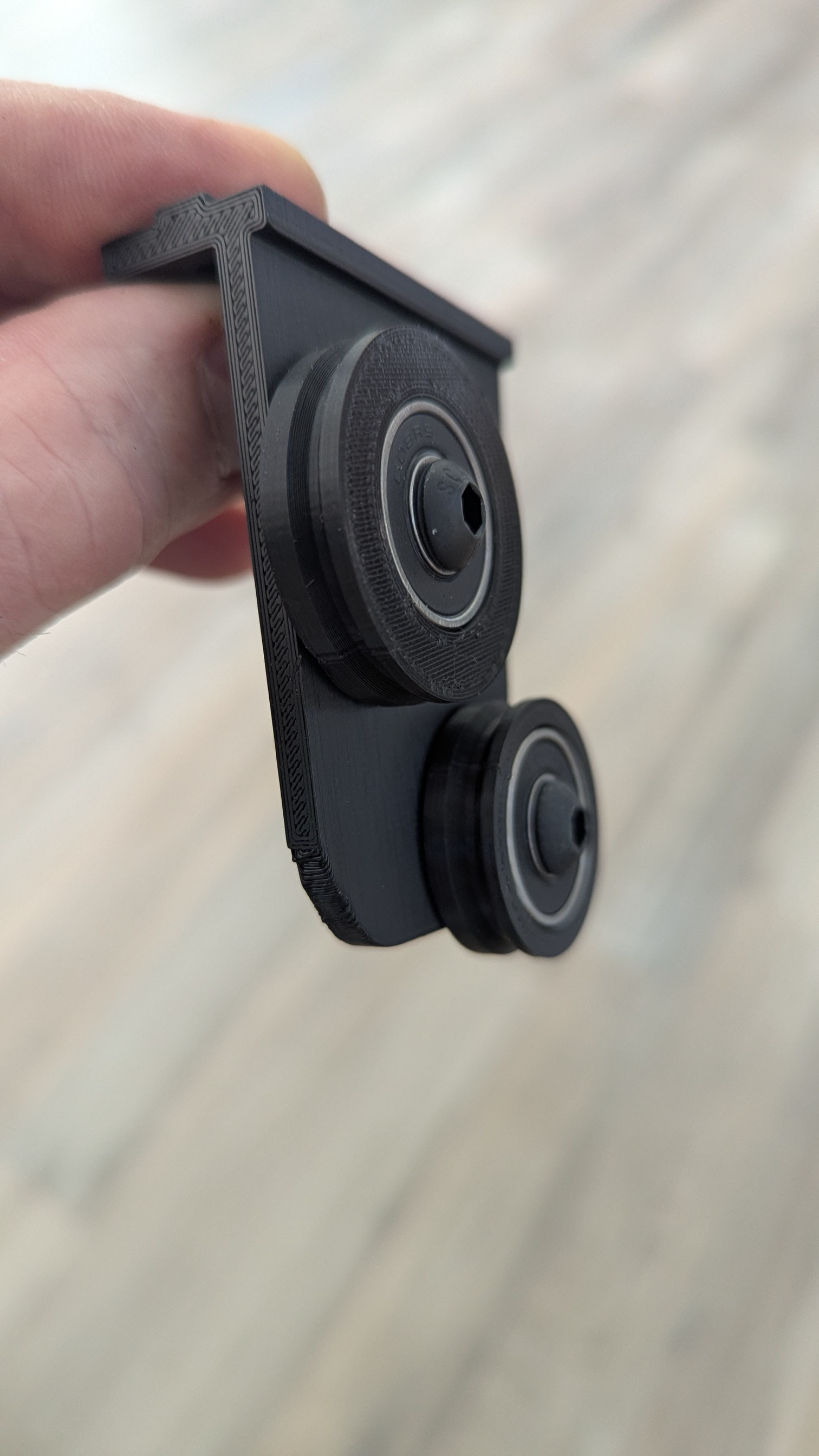
Kinematics
FluidNC has config settings for WallPlotter kinematics. There is very little documentation and it is not “supported”, but it does seem to work OK. Here is how you set it up…
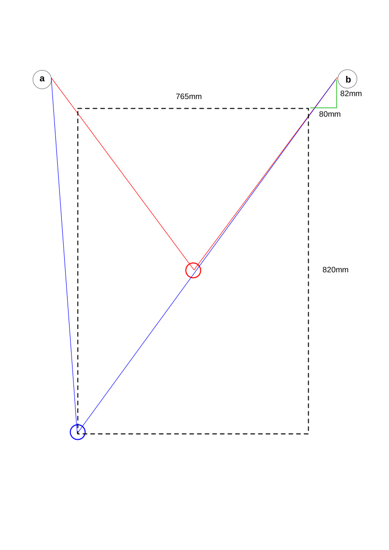
Refer to the above diagram (not drawn to scale) for an example of my setup. The dashed black line is the drawing area. The circles in the top left and right are the pulleys. I wanted the machine home (x0, y0) to be bottom left - refer to the blue lines in the diagram. The red lines are an example of machine home in the center. Here is the kinematics section of config.yaml:
MACHINE HOME: BOTTOM LEFT
kinematics:
  WallPlotter:
    left_axis: 0
    left_anchor_x: -80.000000
    left_anchor_y: 902.000000
    right_axis: 1
    right_anchor_x: 845.000000
    right_anchor_y: 902.000000
    segment_length: 1.000000
If you wanted the machine home to be in the center of your canvas (red lines) it would look like this:
MACHINE HOME: CENTER
kinematics:
  WallPlotter:
    left_axis: 0
    left_anchor_x: -462.500000
    left_anchor_y: 492.000000
    right_axis: 1
    right_anchor_x: 462.500000
    right_anchor_y: 492.000000
    segment_length: 1.000000
Notes:
- All measurements are made from the “anchor points” on the pulleys. If you use the center of the pulleys, the geometry will be a little off. I use the 2 o’clock position on the left pulley and 10 o’clock position on the right. See this post Steps per mm (Wallplotter kinematics) for a discussion.
- In my example the pulleys are symmetric in relation to the drawing area, but technically they don’t have to be. One can be horizontally offset more than the other. They do have to be at the same height however.
- It is important that the gondola is as close as possible to the home position described in the kinematics section when it is at machine x0, y0. More discussion on that in a later post.
- My pulley offsets are 80mm from the canvas sides and 82mm from the top. Technically they can be 0 and 0 but that would not work very well. I’d shoot for 100mm and 100mm if you have the space.
- Default segment_length is 5. The lower the number, the smoother the curves but you sacrifice speed. I have it set at 1.
Motor setup
Here is the motor setup in my config.yaml. Note that I am using slots B and C on the Jackpot board. B = left motor (x axis) and C = right motor (y axis). It is confusing to refer to them as x and y as they have nothing to do with x and y cartesian space, but I tried b: and c: in the yaml and it didn’t work. There may be some relationship with the “left_axis:” and “right_axis:” settings in the kinematics section, but I never really figured that out either. All I know is that these config examples work.
axes:
  shared_stepper_disable_pin: NO_PIN
  shared_stepper_reset_pin: NO_PIN
  homing_runs: 2
  x:
    steps_per_mm: 31.650000
    max_rate_mm_per_min: 5000.000000
    acceleration_mm_per_sec2: 50.000000
    max_travel_mm: 765.000000
    soft_limits: true
    homing:
      cycle: 2
      allow_single_axis: true
      positive_direction: false
      mpos_mm: 0.000000
      feed_mm_per_min: 250.000000
      seek_mm_per_min: 500.000000
      settle_ms: 0
      seek_scaler: 1.100000
      feed_scaler: 1.100000

    motor0:
      limit_neg_pin: 'gpio.25:low'
      limit_pos_pin: NO_PIN
      limit_all_pin: NO_PIN
      hard_limits: false
      pulloff_mm: 2.000000
      tmc_2209:
        addr: 3
        cs_pin: I2SO.19
        uart_num: 1
        step_pin: I2SO.18
        direction_pin: I2SO.17
        disable_pin: I2SO.16
        r_sense_ohms: 0.110000
        run_amps: 0.680000
        hold_amps: 0.250000
        microsteps: 16
        toff_disable: 0
        toff_stealthchop: 5
        use_enable: false
        run_mode: StealthChop
        homing_mode: StealthChop
        homing_amps: 0.680000
        stallguard: 5
        stallguard_debug: false
        toff_coolstep: 3

  y:
    steps_per_mm: 31.650000
    max_rate_mm_per_min: 5000.000000
    acceleration_mm_per_sec2: 50.000000
    max_travel_mm: 820.000000
    soft_limits: true
    homing:
      cycle: 1
      allow_single_axis: true
      positive_direction: false
      mpos_mm: 0.000000
      feed_mm_per_min: 250.000000
      seek_mm_per_min: 500.000000
      settle_ms: 0
      seek_scaler: 1.100000
      feed_scaler: 1.100000

    motor0:
      limit_neg_pin: 'gpio.33:low'
      limit_pos_pin: NO_PIN
      limit_all_pin: NO_PIN
      hard_limits: false
      pulloff_mm: 2.000000
      tmc_2209:
        addr: 3
        cs_pin: I2SO.22
        uart_num: 1
        step_pin: I2SO.21
        direction_pin: I2SO.20
        disable_pin: I2SO.23
        r_sense_ohms: 0.110000
        run_amps: 0.680000
        hold_amps: 0.250000
        microsteps: 16
        toff_disable: 0
        toff_stealthchop: 5
        use_enable: false
        run_mode: StealthChop
        homing_mode: StealthChop
        homing_amps: 0.680000
        stallguard: 5
        stallguard_debug: false
        toff_coolstep: 3
Notes:
- The homing settings are ignored by the stock version of FluidNC. They need to be valid values, but they are ignored. Same goes for the limit pins. I have “limit_neg_pin:” set because I have modified FluidNC to home a Wallplotter, but suggest you set these to NO_PIN for now. More on this later.
- The steps_per_mm: value (31.650000) is based on the diameter of the string spool. That may need some tweaking, but it is very close.
For the “start:” section of config yaml, set must_home to false. This may be ignored as well, but won’t hurt.
start:
  must_home: false
  deactivate_parking: false
  check_limits: false
Build - Part II
Gondola
3d Models:
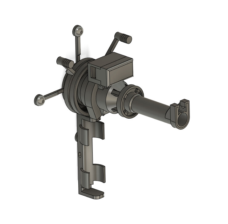
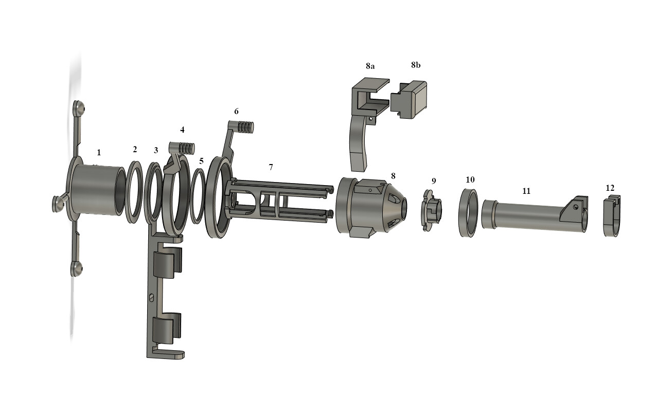
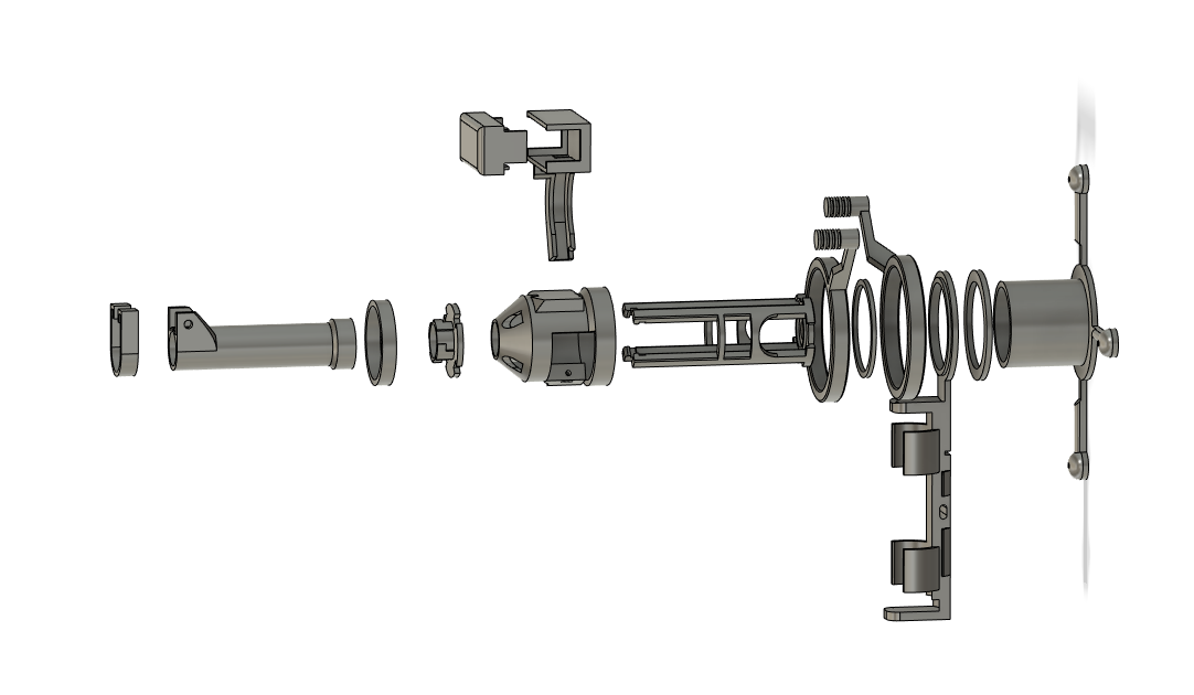
Here are the STL files:
gondola_models.zip (452.6 KB)
Notes:
- I print the gondola spider (1) at the highest quality. I find that the nylon bearing balls rotate better in their sockets at this setting.
- The gondola_cone (8) will likely be oriented upside down when added to your 3d printer’s build plate. I recommend printing it in that orientation using a brim for adhesion.
- Missing from the pictures above are four 1/4" Nylon bearing balls, two 30mm ID x 42mm OD x 7mm bearings, a 40mm x 16mm x .7mm spring, two 1mm bearings, and pen pressure lever. The optional pen lift components are a battery, a servo and the rf circuit. I will address these in a later post.
- Even if you aren’t going with the pen lift, you should still include the battery holder and a battery or weight equivalent for ballast.
- The four nylon bearing balls get pressed into the feet of the spider (1).
- The 30mm x 42mm bearings are pressed into the parts 4 and 6.
- There are two versions of part #7 (gondola_spring_arms) in the models zip. One is for a Pigma Micron pen, and the other is for an Expo fine tip dry erase marker. The spring must be inserted into the gondola_spring_arms before it is inserted into the gondola_cone.
- Pay close attention to the orientation of the gondola_spring_arms (7) in relation to the gondola_cone (8) during assembly.
- I will try to create a quick video of the assembly process when I get a chance.
Still to come:
- Pen lift schematics
- Gondola assembly video
- To home or not to home?
Impressive!!
Pen Lifter Circuits
Transmitter (Jackpot Expansion Port)
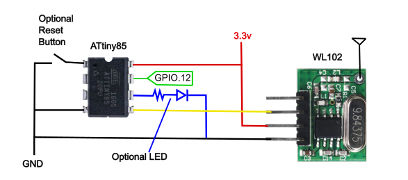
Notes:
- The WL102 uses 3.3v logic level on its DAT pin, as does the ESP-32 (GPIO.12) so we stick with that. The Jackpot Expansion port only has a 5v option, so you either need a 3.3v regulator or if you have a JP1, it is fairly easy to run a trace wire from the 3.3v output of the ESP-32 over to one of the unused pins on the expansion port. The circuit doesn’t draw much current, so the regulator on the ESP can handle it.
- I included an optional led that indicates PEN UP when lit. As shown, it is driven from a GPIO which will work but isn’t the best way to do it. I recommend driving the LED with a transistor if you have one. A 330 ohm resistor should be in the ballpark for whatever color LED you have.
- In an earlier picture, I show a transmitter plugged directly into the expansion port but I was unable to get that to work with any of the cheapo transmitter/receiver combos I had laying around so an ATtiny was necessary to make it work. You could of course use just about any microcontroller. I wanted the smallest one I could find for the receiver on the gondola and the ATtiny fit the bill, so I used the same on the transmitter.
- Note that you will need a way to program the ATtiny. I used a clone of the Sparkfun Tiny AVR Programmer.
- The antenna on the WL102 is optional. More discussion on that below.
Receiver (Gondola)
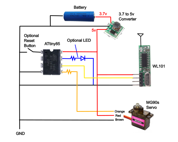
Notes:
- The servo needs (likes) 5v, as does the WL101 receiver, so we use 5v logic levels on the gondola. The battery I chose was 3.7v, so we need a converter. All these parts are available on Amazon.
- I use a 1.8K ohm resistor with the LED on this circuit due to the higher voltage.
- A 1K ohm resistor is used on the servo signal line (orange) to protect the ATtiny from glitches in the servo’s internal circuitry.
Transmitter Sketch:
// Polargraph - FluidNC Expansion Card Code (ATtiny)
//
// Configure GPIO-12 in FluidNC config.yaml as output
//
//    user_outputs:
//      ...
//      digital1_pin: gpio.12
//      ...
//
// GRBL Code:
//    Pen Up:    M62 P1
//    Pen Down:  M63 P1
//

#include <Arduino.h>
#include <VirtualWire.h>

const uint8_t PEN_PIN = 2;
const uint8_t LED_PIN = 1;    //OPTIONAL LED
const uint8_t TX_PIN = 0;

const uint16_t TX_SPEED = 4000;
const char *ON = "1";
const char *OFF = "0";

void setup() {

  pinMode(PEN_PIN, INPUT);

  pinMode(LED_PIN, OUTPUT);  // OPTIONAL LED

  // CONFIGURE VIRTUAL WIRE
  vw_set_tx_pin(TX_PIN);
  vw_set_ptt_inverted(true);
  vw_setup(TX_SPEED);

}

void loop() {
  uint8_t penState = digitalRead(PEN_PIN);

  const char *msg = (penState == HIGH) ? ON : OFF;
  digitalWrite(LED_PIN, penState ? HIGH : LOW);  //OPTIONAL LED
  vw_send((uint8_t *)msg, strlen(msg));
  vw_wait_tx();

  delay(20);
}
Receiver Sketch:
// Polargraph - FluidNC Pen Lifter on Gondola Code (ATtiny)
//

#include <Arduino.h>
#include <VirtualWire.h>

const uint8_t SERVO_PIN = 0;
const uint8_t RCV_PIN   = 1;
const uint8_t LED_PIN   = 2;  //OPTIONAL LED

// Servo pulse widths (microseconds)
const uint16_t PULSE_UP   = 1600;     //throw top - increase the difference for more throw
const uint16_t PULSE_DOWN = 1175;     //throw bottom - possible valuies 900–2100
const uint16_t frameTime  = 20000;
const uint16_t stepSizeSlow   = 50;     // speed - increase for faster use 2 - 60
const uint16_t stepSizeFast   = 60;     // speed - increase for faster use 2 - 60

uint16_t currentPulse = PULSE_UP;
bool penUp = true;   // remembers last state

void setup() {
    pinMode(LED_PIN, OUTPUT);  //OPTIONAL LED
    pinMode(SERVO_PIN, OUTPUT);

	//VISUAL BLINK ON START FOR OPTIONAL LED
    digitalWrite(LED_PIN, HIGH);
    delay(500);
    digitalWrite(LED_PIN, LOW);
    delay(500);
    digitalWrite(LED_PIN, HIGH);
    delay(500);
    digitalWrite(LED_PIN, LOW);
    delay(500);

    vw_set_rx_pin(RCV_PIN);
    vw_set_ptt_pin(255);  //originally: vw_set_ptt_inverted(true);
    vw_setup(4000);
    vw_rx_start();
}

void loop() {
    uint8_t buf[VW_MAX_MESSAGE_LEN];
    uint8_t buflen = VW_MAX_MESSAGE_LEN;

    // Update only when a new message arrives
    if (vw_get_message(buf, &buflen)) {
        if (buf[0] == '1') penUp = true;
        else if (buf[0] == '0') penUp = false;
    }

    // OPTIONAL LED indicator
    digitalWrite(LED_PIN, penUp ? HIGH : LOW);

    // Determine target pulse
    uint16_t targetPulse = penUp ? PULSE_UP : PULSE_DOWN;

    // Smooth ramping
    if (currentPulse < targetPulse) {
        currentPulse += stepSizeFast;
        if (currentPulse > targetPulse) currentPulse = targetPulse;
    } else if (currentPulse > targetPulse) {
        currentPulse -= stepSizeSlow;
        if (currentPulse < targetPulse) currentPulse = targetPulse;
    }

    // --- INTERRUPT-SAFE SERVO PULSE ---
    noInterrupts();                     // <‑‑ critical - disables VirtualWire during Servo Moves
    digitalWrite(SERVO_PIN, HIGH);
    delayMicroseconds(currentPulse);
    digitalWrite(SERVO_PIN, LOW);
    interrupts();                       // <‑‑ critical - re-enable VirtualWire

    delayMicroseconds(frameTime - currentPulse);
}
Sketch Notes:
- I use VS Code with Platformio as an IDE. The above code should work in Arduino IDE but you won’t need the first line ( #include <Arduino.h> ).
- If you need help programming an ATtiny, just ask. There are nuances involving USB drivers and clock speed (fuses).
- I used the VirtualWire libary because it is small. Otherwise it isn’t the best choice. It’s successor (RadioHead) is much more robust but uses almost all the memory available on the ATtiny. One problem with VirtualWire is that it takes over the clock (Timer0). This messes with things like millis(), delay() and timing in general.
- The transmitter sketch is ALWAYS transmitting. This may be problematic depending on your environment - I have 6 RF devices in my house that use the same frequency (433MhZ) and all of them were disabled when the transmitter was powered because the signals from their remotes were being trampled by the WL102. My first solution was to remove the antenna from the WL102. That worked fine because the gondola is only a few feet away, but I am in the process of testing out a sketch that only transmits for 5 seconds after a change in the pen state. You may wonder why I didn’t do that to begin with. It’s complicated. It was for me anyways. If you want more info, just ask.