Has anyone ever had an issue with the steps_per_mm changes not taking affect on a stepper motor? The new settings are being saved (they show up after fluidnc is rebooted), but the distance that the motor turns is unaffected. I have 2 motors and one does work as it should after changes, but the other doesn’t seem to be affected. I have swapped driver boards as a sanity check, but no change there. I suppose I should elaborate a bit…
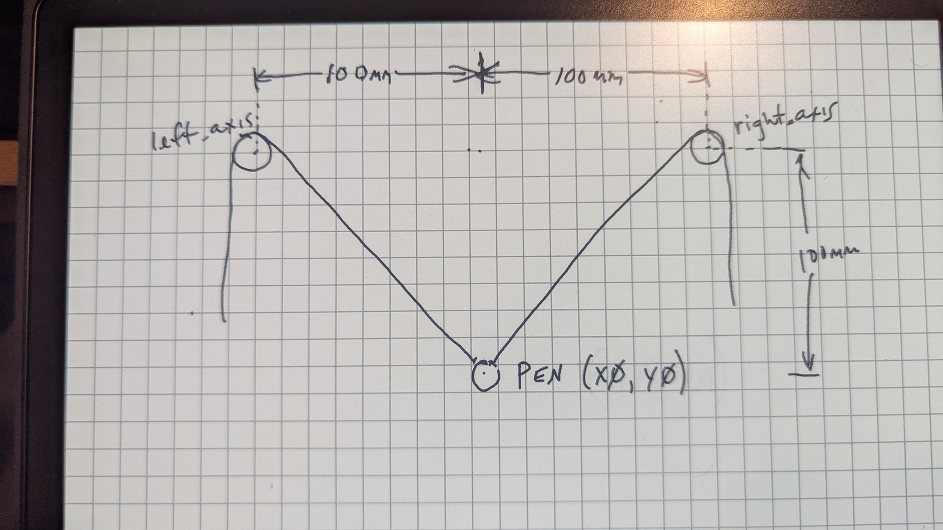
I am using “WallPlotter” (Polargraph) kinematics. This mode isn’t supported by the fluidnc guys but they do offer it as an option in the settings. Maybe it’s a firmware deal? It’s just weird. There is a left and right motor in the top corners configured as left_axis and right_axis. Everything is identical in the “axes:” sections of the motors, but only the right one is affected by the steps_per_mm setting. It’s driving me nuts!!!
My guess is that something in the kinematics definition is “overriding” the second motor with the settings from the first, as if it were a cloned parallel axis, but this is only a guess.
Thanks for chiming in Tom. I can’t wrap my head around it. The lack of documentation and the fact that they don’t support it makes me think that they started down that path but abandoned it. I’m definitely chasing my tail at this point. In addition to a translation that is close but not quite (gets a little skewed the closer it gets to the motor points in the upper corners), there is a crazy bug that happens when you send it to its current location. For instance:
G01 X100 Y00 (goes to x100 y100 as it should), then if you send the same command G01 X100 Y100, it goes to x-143 y2.7. Then the best part, when you send it back to the origin from there G01 X0 Y0 it goes back to x100 y100 then immediately to x0 y0. I’m kind of disappointed because I really wanted to use FluidNC for this and my AI assured me it would work perfectly .
This kinematics does not use homing. You must manually move the pen to the 0,0 position as defined by your config settings and then reset the firmware. In the example below, you would move the pen to the center on X and 100mm below the anchors.
Also, how does your config.yaml compare to the example on the FluidNC Wiki?
Yeah, I think I have that sorted. One thing that I am not sure of is what exactly those anchor points are. For instance, the string from the motors is routed via pulleys located at top left and right. So, are the anchor points the center of the pulleys? My pulleys have a radius of 12.5mm and the string is routed on the “inside” of the pulleys. So, it would seem important to the geometry translation, as it would be possible to design a system where the string is routed to the outside of the pulleys. Am I describing that clearly or do we need a pic?
My understanding is that I use those settings to define the origin of the drawing area. So, in that example, the origin is 100mm below the anchor points and centered between them (they are 200mm apart). I am in the ballpark using the example, but I can’t get it calibrated to my satisfaction. AI seems to think the anchor points are the center of the pulleys, but I would think that pulley diameter would have a say in the translation geometry.
Yes… Adding to the original. Just wanted to make it more interesting to watch. It will be capable of drawing using both modes. I’ll try to come up with a picture….
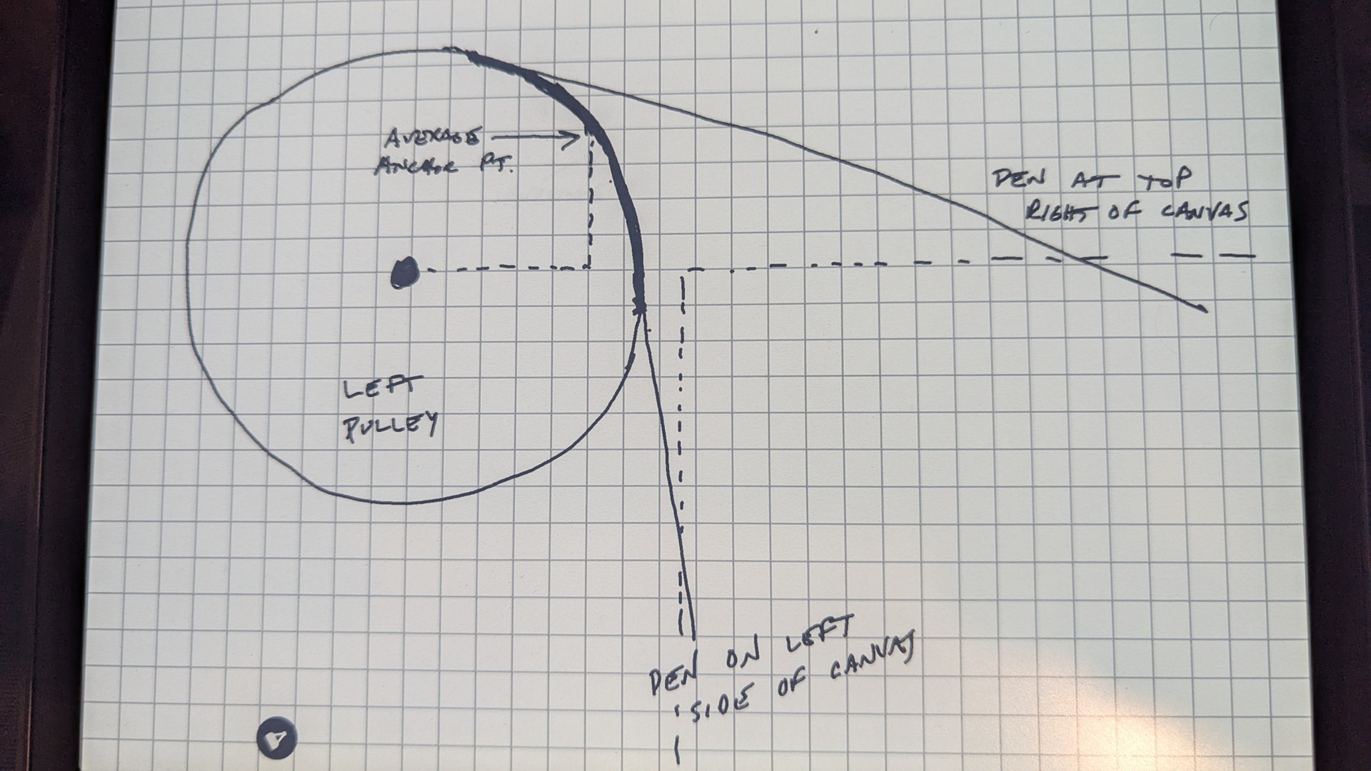
Here is my crude drawing that represents the example that Jim referenced. The underlying issue with this type of design is that there is no way of homing the machine, so it is done manually. The docs don’t specify, but in this diagram, the assumption is that the anchor points are in the center of the left and right axis pulleys. So, to home the machine using the settings referenced by Jim, you move the pen to the spot shown in the diagram and restart Fluidnc. The question is, are the anchor points actually in the center of the pulleys, or are they affected by the diameter of the pulleys?
After a few tests and some pondering during a long walk with my furry best friend, I came to the conclusion that the translation in the firmware is flawed. The geometry is pretty basic - take a point (x,y) in the cartesian coordinate system and draw lines from the top left and right corners of the drawing area (anchor points) to (x,y). Do some math to calculate the line distances and move the left and right motors accordingly. The problem is that the math only works if the anchor points are fixed. Since there is no provision to enter a pulley radius in the firmware, it must assume fixed anchor points (zero radius pulleys). So, the greater the radius of the anchor pulleys, the greater the error in the translation, which is technically only accurate at the origin. Using the center of the pulleys as anchor points is probably the worst thing that you can do (thanks AI). I think the answer is to determine an average location based on the tangential point range at which the string comes off of the pulleys (which is still not entirely accurate but maybe acceptable) or modify the firmware to account for the pulley radius for perfect accuracy.
Feels like maybe they settled on “just use pulley centers” as an abstraction to get things running, then never got around to “add pulley diameter” to the kinematic calculations.
Yes, I think that’s a good assumption. I don’t think there is anyone using one of these to create mechanical drawings, so accuracy isn’t a priority. After a lot of tweaking and trial and error, I have found some settings that are surprisingly accurate. I decided that the average anchor point is about the 2 o’clock position in that darker area in my diagram above. Using that, I have achieved accuracy less than 1mm in the bottom 3/4 of the canvas area. Once the pen is in the top 1/4 of the canvas, the tangential point at which the string leaves the pulley is closer to 12 o’clock and is significantly deviated from the chosen anchor point at 2 o’clock. It is still well within tolerances for drawing pictures.
You can use an approximation of the location the wire comes off the pulley. It will be close to correct most of the time.
The maslow kinematics have accuracy issues whenever you get close to either pulley. Whenever the direction of gravity is perpendicular to one of the strings, the gravity isn’t doing enough to keep that string straight.
That doesn’t mean it won’t work. But it means you need to temper your expectations. It should be repeatable in the center or near the bottom. But the top is going to be rough. So don’t do a high resolution chevron pattern. But if you did the head of a lion, it would probably draw pretty well.