PCB Component Repairs

No worries, it definitely didn’t immediately come across like that, I just couldn’t figure out what you were referring to so my last option was that it was a bit tongue-in-cheek.

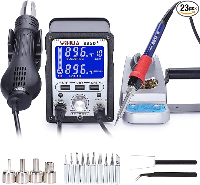
The rest of that comment looks good to me. I haven’t had a play with the Pinecil but people seem to like it. I’ve seen things like the Fanttik iron and it also looks reasonable. With all of those options I’d rather see a little more variety in tip size but ultimately that’s only because I’d be wanting to find a single one that works for me, not because I think you actually need dozens of options. Out of the ~10 Hakko tips we have, 99% of the time I use 2 different ones.

The other thing is that the body of the tip seems quite narrow. That’s not a problem itself but does mean that the temperature sensing and power will need to be a bit better as there’s not as much thermal mass to counteract it. If it’s working for you and making good looking joints without being weird then that’s fundamentally the goal! I’ve said it above but fundamentally once you’ve got the skills then damn near anything will work, it’s just about how easy it makes the process for you and how much finesse it requires to get a good result. Whatever it is, it’ll likely still be way better than the old-school style separate tip/heater with the curie point temperature settings or whatever. Those are remarkably garbage. It’s also often one of those things that you don’t notice until you go to something better and then have to go back!

The solder link goes to the iron again so I’m not sure what the solder is. 0.8mm is a good middle-of-the-road size. That’d be around the size that I use the most often for most things. Similar thing with that flux. I prefer the precision of a syringe for application because I’m typically using it on small stuff and you really don’t need much, but you could also potentially apply it with a stainless steel pick or something quite easily, or the wood stem of a cotton swab, etc.

Soldering wires to end stops is definitely a use case that I don’t run into much. Whenever I’ve ended up in that position I much prefer using crimped faston connectors instead of direct soldering because it’s easy to have too much heat melt/deform the microswitches. Given the way the microswitches are constructed, the position of the pin defines a lot of the internal geometry and how they work/where they trigger etc so bending the pins with heat or having them shift can affect their function more than I’d like. That’s just a process control thing, though. If you can get them soldered without excess heat going into them then it’s a case of whatever works!

1 Like

I think those are intended to swirl the air around the thing you’re heating, specifically for heat-shrink and low-melt butt splices etc. The shielding is a side effect.

Like I said above, give one a try and see if it improves things for you. We use them in some cases but I find the extra hot mass on the tip leads to me just burning myself or melting things more often, so I seldom bother putting it on.

1 Like

Looks like my old iron, only mine didn’t have those fancy vent holes.

2 Likes

Interesting technique!

2 Likes

Sure hope you didn’t hold it the same way she is :rofl:

3 Likes

There’s a pretty significant problem with that picture…

Yeah, that picture is staged. No soldering was taking place. Hopefully no burns either.

1 Like

Omg!!! That pic!!!

3 Likes

How did I miss this thread! I had an abnormal stack of jackpots with a few bad components. I upgraded my microscope from,


Amazon.com to


Amazon.com man!

Not only is it set up way better to use your hands for other things it works crazy good, and is super clear. Highly recommended.

Turned on my trusty 7-8 year old hot air station, and the element popped. Had a hard time trying to figure out which replacement element and the air pump was kinda busted, full blast or nothing, so I picked up


Amazon.com, it is very nice replaces my old station well, much smaller, better iron, better air. They both also have like a snooze and auto off feature, it is very very nice to have. Sometimes you get distracted and knowing they cool down by themselves is a great piece of mind and I also find myself taking my time and being more careful because I do not feel the need to rush the setup.

I popped off a few esp32 5v regulators and a bunch of the jackpot tiny input diodes, very easily.

The only downside I see is I wish the LCD on the microscope was further back, I will probably make a new mount for it and move it back like 6"-8". Heck maybe even a nice little electronics workbench is due.

4 Likes

Man you missed out on the Vevor Microscope a while back. I know several of us picked one up. I want to say it was around $15 and it works awesome! Haven’t tried to use it for soldering (although I should lol) but it works great for inspecting endmills LOL.

Went and found the old thread…

I had grand plans for a “electronics” section on my new work benches, but it became like any other flat surface around here and you cant even see it anymore :man_facepalming: One of these days I will clean it up and set it up how I want, and hurry up and post pics before its all lost again :rofl:

4 Likes

Not only that — she now has vent holes in her fingers!

2 Likes

Oh shoot!

3 Likes

Yep what a deal. I’m still thinking that was a mistake on somebody’s part at Vevor, because they changed the price pretty quickly to something more in line with that one that Ryan linked to. But if it was a mistake, to their credit they honored the sales orders and shipped the units! I have used mine a handful of times, and it comes in very handy.

3 Likes

Mistake or not I am glad I got one while the deal was there!

1 Like

I haven’t used it for soldering. But we did use it for some splinter extraction and it worked great. My son had a metal splinter that neither of us could see until we tried the scope.

5 Likes

Splinter removal. Now that’s a great use for it!!! Hopefully I will remember that next time that comes up LOL

3 Likes

Good idea, Occasionally I get the invisible ones that drive me nuts for a couple days.

2 Likes

did someone say microscope, this was kinda cool.

I spent some time, I was trying to figure out where they got 60 bucks from, as It does not add up to that to me.

this post is better:

1 Like

True, we haven’t been in much of a build phase at work so the last use for the Mantis viewer was pulling an aluminium splinter out lol.

Edit: Which it kinda sucked at, to be frank. I’d have preferred to use my actual microscope.

1 Like

So, @bitingmidge sent me the controller and it arrived late last week. I spent a bit of time looking over the board and probing around at things. What I thought looked like a dead FET and diode in the photo was actually just the red glue-spots from the components being mounted on the bottom side. Both the FET and diode tested fine on a diode range, as did all the other discrete diodes, the bridge rectifier, the fuse, the NTC inrush resistor, the MOV, etc. Just to put everyone’s mind at ease, I checked the electrolytic caps closely and with an LCR meter. All 4 showed the correct capacitance and reasonable ESR values, which was somewhat of a surprise given I was measuring them in circuit. Either way, I can’t see anything that would indicate that these caps are getting any reasonable amount of ripple current and they’re long-life 105degC caps so wouldn’t expect an issue there.

During the probing around, I couldn’t find a continuous trace from the phase input to the bridge rectifier. It turns out the incoming phase runs to the fan’s motor connector and back, presumably so it can go through a thermal fuse/cutout of some kind. I just bridged across that with a piece of solid-core hookup wire.

I ganged up a couple of bench power supplies and applied 60V to it with no noteworthy result. The DC link came up as expected but it wasn’t enough to start it switching.

I then tried running it on 230V via an isolation transformer (critically important if you’re going to be poking around at mains voltage electronics, in my opinion). It started making the periodic clicking noise that’s common when power supplies fail to start and go into ‘hiccup’ mode. An isolated HV probe on the FET showed that it was switching cleanly for a few hundred us every half a second or so. I probed around a bit more and found what was likely the extra-low voltage supply connection. It showed a few hundred mV rise on every hiccup but nothing more which led me to conclude that something was likely shorting out the ELV supply.

I grabbed the thermal camera and had a look around. Spotted a single hot spot that was separate from the part of the board with the switch-mode power supply on.

IR_00231
The lower right is where the SMPS components are. The upper left is the unexpected hot-spot. Ignore the temperature datum in the middle, I forgot to turn it off and it’s in Fahrenheit… Blech.
IR_00234
Underside of the board showing the SMPS in the top right with the hottest components being the MELF shunt resistors for the switching path. The bottom left hot spot is the the warm part of the plane under the unexpected hot spot.

IR_00232
On closer inspection it was a large ceramic cap, connected between a large trace and a copper pour. The heat is localized enough that it’s definitely the cap getting warm, not something else around it.

I probed the connections either side and found a bunch of common connections to other parts of the board, as well as a smaller cap next to it leading me to conclude that it was probably just a voltage rail storage cap.


I moved the big electrolytic out of the way and removed the cap. The red arrow shows where it was, didn’t grab a before photo.

IR_00237
I powered it back up and the board beeped once, no more hiccup noises and the thermal camera shows lots of other parts of the board getting warm as expected. You can see the controller for the secondary step-down circuit, a choke and the microcontroller as the warm spots in the top left. They show up pretty bright but in reality they’re at around 35-40 degrees C, so about where I’d expect them. I probed the pads from where I had removed the cap and there was +24V stable there, as expected.


I powered everything down, discharged the DC link cap through a resistor and then replaced the ceramic cap with a 10uF 35V X7R from my inventory. Powered it up again, made sure everything still looked fine. Powered it down, removed the soldered link on the fan supply connector, cleaned up the tops of the components that were mounted to the heat spreader plate, gave the thermal pads a check over and quick clean and then reassembled the whole thing. Ready to go back for testing!

6 Likes

Good troubleshooting methodology!

You just have to love IR cameras for troubleshooting.
I’m really curious about that single failed cap on a LV DC rail. It had to be a cap that was failing to a low resistance short, which is curious.

Did you examine the failed cap at all to see if there are any signs of what happened to it?

I would have suspected those aging electrolytics way before I would have suspected an SMT ceramic cap.

Hopefully this goes back and has years more service.

Repair, reuse, repurpose, recycle. Repair being the besrt possible outocome.

3 Likes