I have a BigAss Fan. Several of them actually, and they are very very good as far as ceiling fans go.
Yesterday, one of them flatlined. I noticed the light was a bit dim, so cranked it up and all function went away.
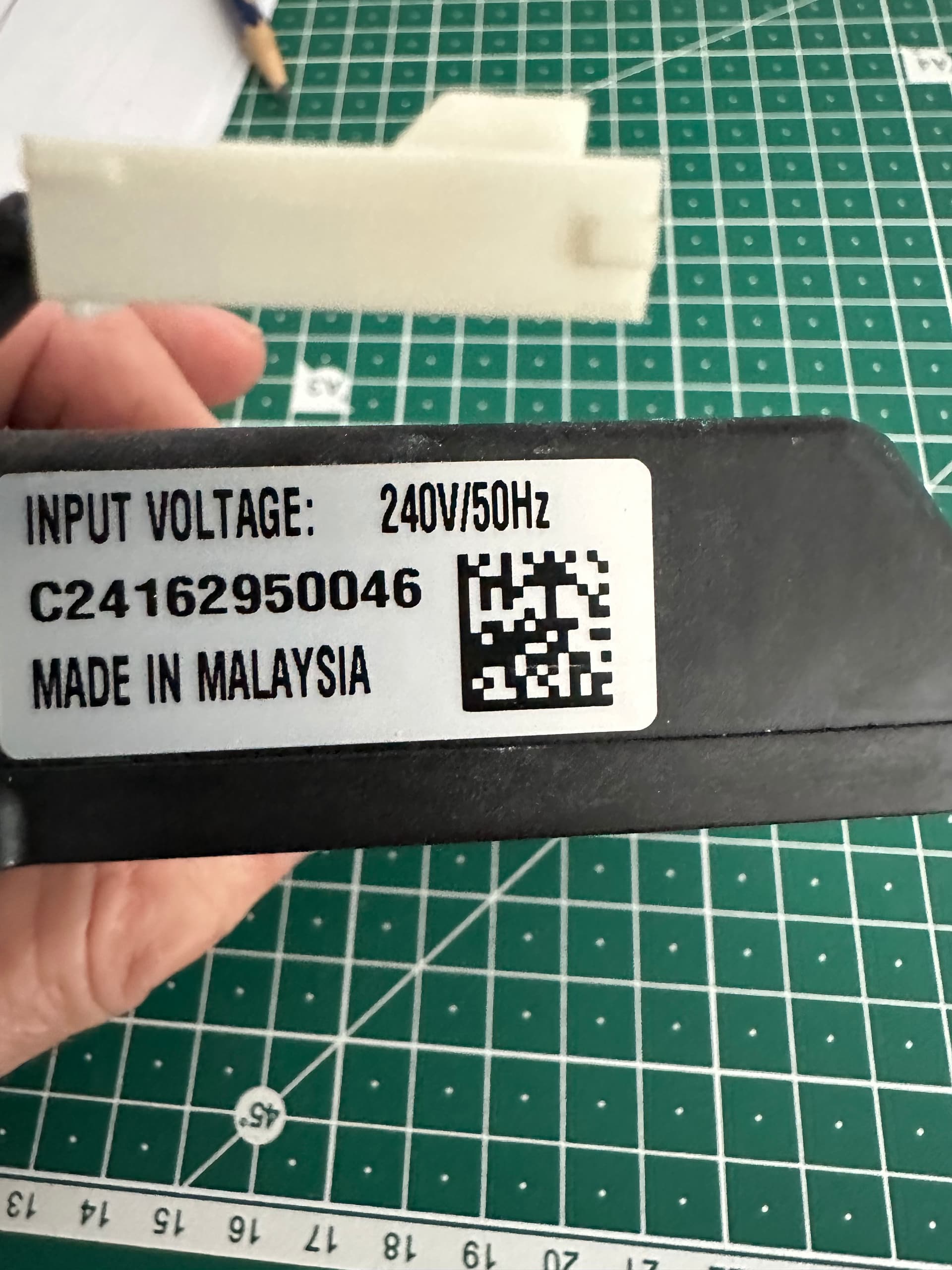
240v supply is OK, my GUESS is that one component in the power supply has gone to sleep.
I phoned the supplier, who were friendly, and very helpful right up to the point where they discovered they hadn’t made that model for eight years and there are no parts available.
I’ve found a company which will repair electronics - a PCB is $100 for diagnostics and there’s a 3-6 month wait unless I pay an “express” fee of $300.
I’ve pretty much figured out where the wires are going, and if it wasn’t playing with 240v on one end, I’d have a crack, but I wonder if anyone can point me in a direction of just how to start? Or should I just stay away from it all together?
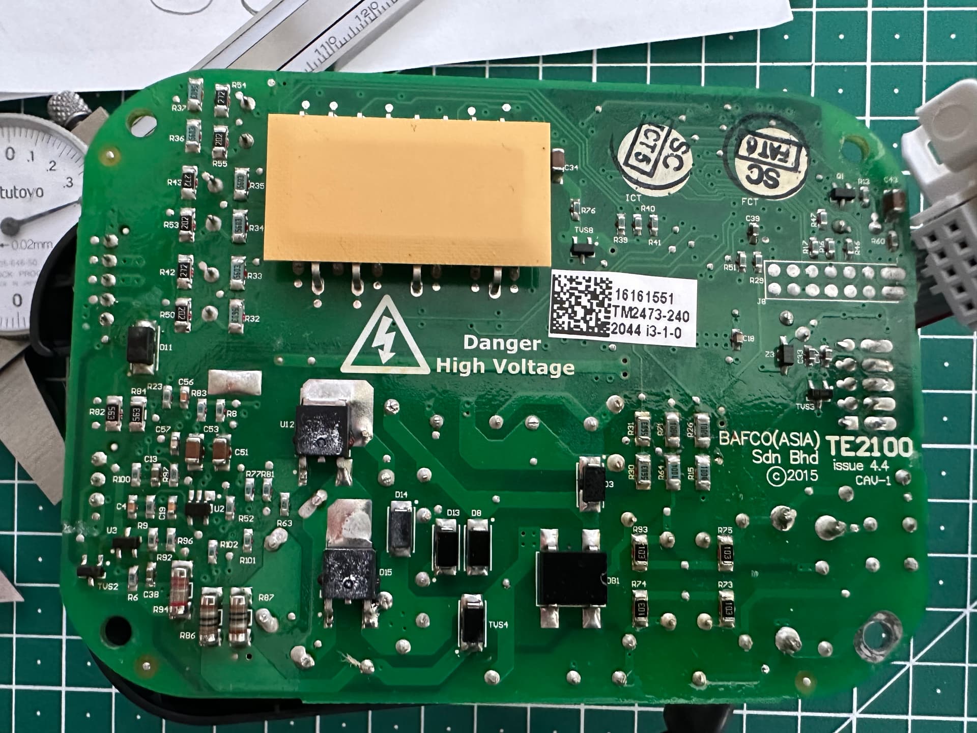
That’s a surprisingly nice looking little board, actually.
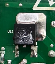
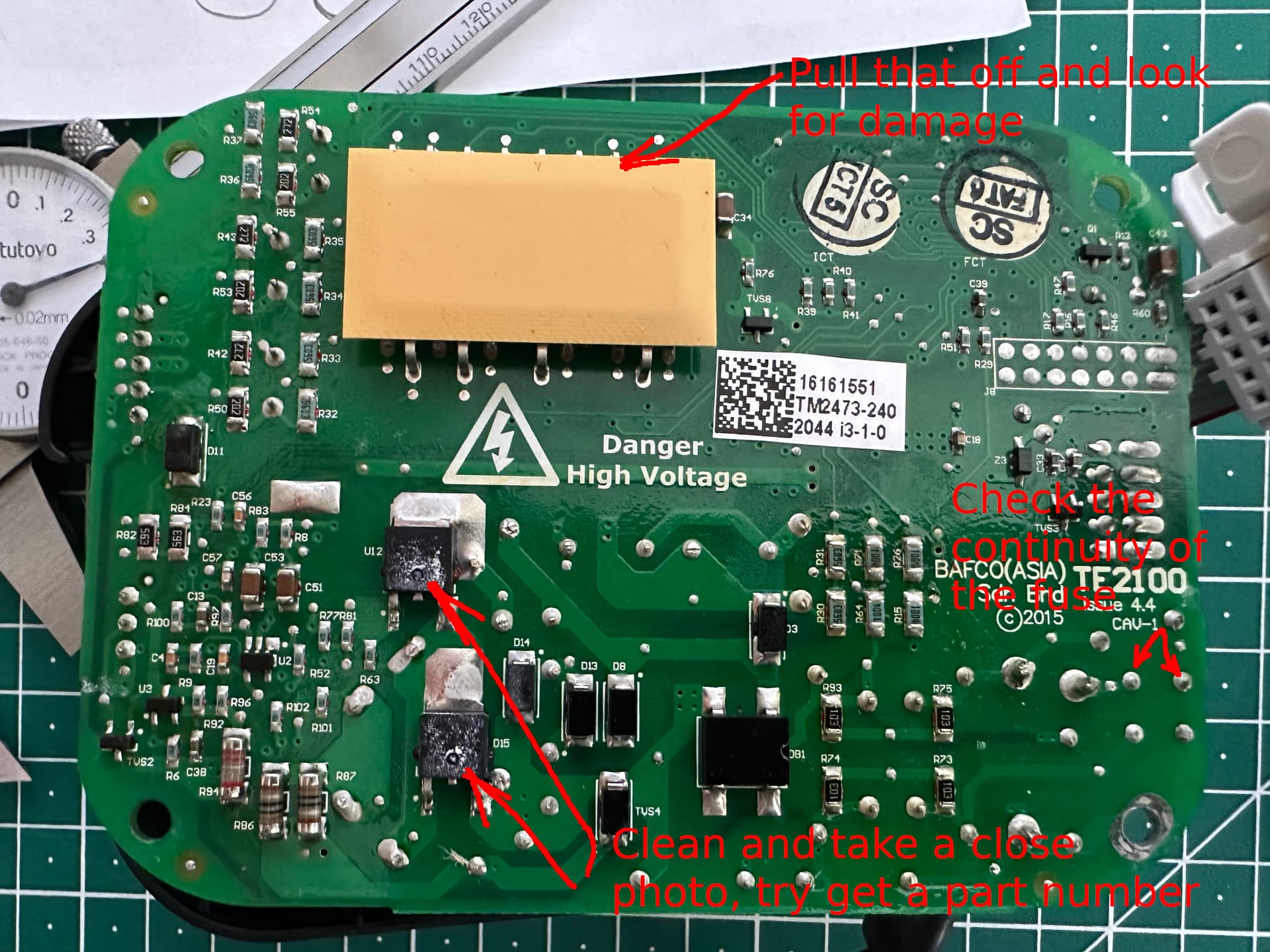
U12 looks dead, to me. (Edit: so does D15)
You can see where the package is bulging out the sides. Given the layout of traces around it, it’s a MOSFET or IGBT. That part and the diode D15 below it will be the main power semiconductors, so they’re always what will die. It’s quite possible that D15 died ‘softly’ which then cause U12 to die energetically when it next turned on.
There’s also something odd under that thermal pad at the top of the photo, can you remove that and take a look for anything damaged?
I think that electronics repair is generally something that isn’t viable as a business these days, at least outside of situations that have published clear repair documentation. It’s simply too time consuming and too complex in most cases with it being too likely that it’s an unsolvable issue due to it being something firmware related or a complex failure.
What’s the unit actually doing? It might be possible to replicate it with something else off-the-shelf…
240V electronics isn’t ‘that’ dangerous, but I’d never recommend anyone poking around with mains without using some precautions. I personally use isolated probes and an isolating transformer, where possible. With care you can use just one of those items but you’ve gotta be careful about blowing up your scope or bypassing the isolation using the scope probes and potentially making a situation that’s more dangerous than when it was on the mains in the first place! It takes a bit of care and attention to do in a way that isn’t hazardous.
The easiest approach is usually to just take a look and identify things that are clearly damaged, like U12. Then check things that can be easily tested like diode testing D15. Replacing those parts and trying again has a solid 50/50 shot of it coming back to life. If there is another fault somewhere it’ll just die again, though.
Edit: There’s also a fuse, F1 as well as a MOV that would be easy checks.
You could also try asking them if they have any repair documentation that could be shared? Even a schematic would make life much easier in terms of repair potential.
Failing that, worst case I’m happy to take a poke around at it and try save it if it’s not super urgent.
Potentially, although I suspect it’d be a little tricky.
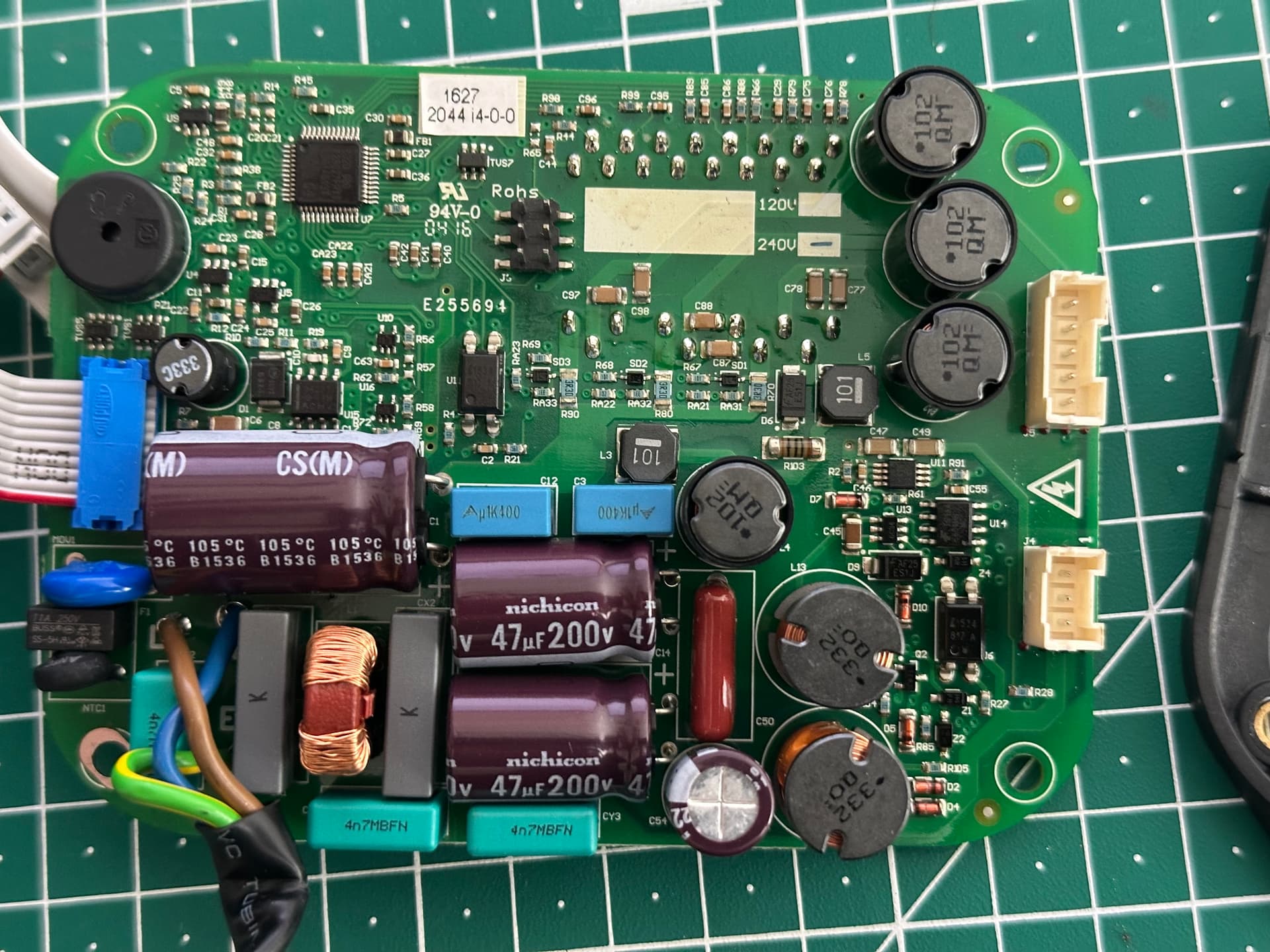
That board is quite a lot more complicated than a typical fan speed controller. Most of those are triac based dimmers and assume the fan motor is a typical shaded pole AC motor.
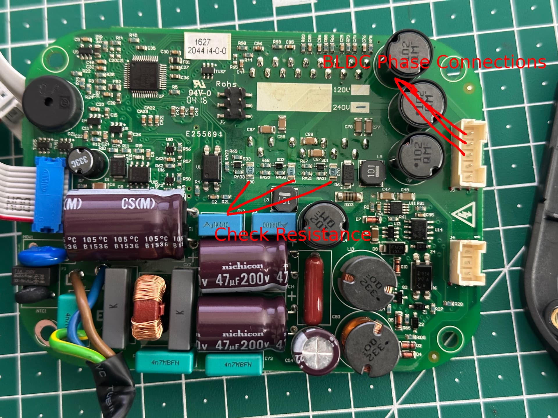
In this case, it’s converting it to DC and then the output has quite a lot of connections which makes me think brushless DC motor. I’m guessing that crazy package IC that’s under the thermal pad is probably some kind of dedicated BLDC controller or 3-phase intelligent power module or something weird like that. The phases will be going through those 3x inductors before hitting the 5pin connector. I’m not entirely sure why it’d need 5 pins, typically that’d be 3 wires or 6 wires but maybe there’s thermal feedback or something.
Still, a BLDC controller isn’t exactly hard to come by, either.
I’d also just take a close look and see if you can see anything else burned, misshapen or whatever. If there’s anything that looks suspicious then get a decently lit close up photo of it and post it up.
I think I’ve identified what would be the 3 connections for the motor windings. You could measure the impedance between each pin on the connector going to the motor (1 to 2, 2 to 3, 1 to 3) and verify they’re all the same. That’ll tell you that the motor should be ok, at least.
I’d give it decent odds that replacing those 2 damaged looking components and potentially the fuse will make it do something, at least, assuming that weird power module thing isn’t damaged.
All the parts in that range are mains voltage capable, so I think it’s likely that the BLDC motor is running via the inverter off the rectified mains and the dead parts are probably just a buck converter for the aux supply.
That means that potentially if you were feeling frisky you could try to figure out the aux supply voltage and power it up from a bench power supply to see if something’s dead in the logic section which is what killed the power supply or whether the power supply just died due to overheating/thermal grease drying out etc.
Also the board is conformal coated from the looks so it might take a bit of aggression to get it to probe nicely.
This would be my goto solution. Now that you know more (after some awesome research), do you know what it is doing? Is it just a power supply? Or a motor controller?
It’s clearly an AC-DC stage then a 3 phase inverter. It doesn’t seem to have enough extra componentry on the phases to be a sensorless BLDC controller. There are extra pins that could be providing position sensing so it could be a sensor BLDC controller. It could also just be a straight up 3-phase AC induction motor controller.
It looks like some of the designs have lights which would make sense for some of the extra pins.
Then there’s some kind of other part with a ribbon cable that I’m guessing is for a screen and some buttons to control it all.
In terms of replacing it outright, the biggest thing would be figuring out what kind of motor it is. Then it should be able to be replaced with a simple controller if needed.
These things look pretty awesome. Them being BLDC motors means they’re almost infinitely speed controllable in a way that stays cool, efficient and silent while a shaded pole fan can’t speed control reliably at low speeds, gets noisy and isn’t efficient.
I think it’s probably one of those things where you’re seeing both the incredible value for money of a massed produced product that has been optimized to within an inch of its life compared to a top quality moderate volume product that’s kind of selling into a niche market.
It’s kinda like comparing cars. Something that costs 10x as much doesn’t have 10x as much ‘stuff’ in it or 10x as much engineering that has been done on it. Hell, some of the most expensive cars in the world have significantly less engineering done to them! It’s that they sell fewer of them so the amortized cost is so much more, etc.
@jono035@jeffeb3 and everyone else who has contributed thus far.
Thank you all so much - of course I chose a time when I was away from the forum for a day, but will be back with detailed responses later today - for now -
The fans were (and probably still are) significantly better than anything else on the market at the time. For a start the blades are actually aerodynamically engineered rather than being bits of flat hardboard - so in terms of moving air, they are super efficient and absolutely silent because of the lack of tip vortices - ie no fan “woosh” (more on that later).
As some have noted the motors are DC and again, silent.
I will mark up some pics later, but for now - the controller is controlled by what I think is an IR remote (I will check) there is space to add a wifi module, which I haven’t done. There is no direct mechanical control.
The connectors that Jono has marked BLDC phase connections I think are the ones that connect to the motor - five speeds, plus an oscillating “woosh” mode which is supposed to emulate the variability of an actual breeze. There’s a timer too, and I presume that all of that happens in the board somehow.
The smaller connector beside it I guess is to connect to the built-in light (which is a dimmable LED)
The ribbon connector at the other end of the board goes to a series of LED’s which indicate the fan speed or mode.
I really can’t stay at the moment, but will be back in a few hours to digest all you have written above, Again, thanks to you all!
Likely all of that is within the controller which is the black square thing with a lot of pins at the top left of one of the photos.
Yeah, it looks separate and low current enough that this would make sense.
No hurry. It was a little strange to get no response for so long but as you can see, it nerd-sniped me pretty hard anyway so I was getting close to trying to draw out a schematic for it before I decided that wasn’t likely to be helpful!
As I said above, my guess is that it’s likely repairable enough to be worth a try.
From Aus that wasn’t possible (I tried) but will write to the US headquarters today.
A bit out of order now, but that’s an interesting proposition - It needs a few separate bits to make it go, but we can locate them in the ceiling. Maybe could be controlled by one of those 32 wifi thingos ( ) - if we break down what it’s doing - there’s an AC-DC converter, a speed controller (and on/off switch) for the fan, and a controller -on/off and dimmer for the light. There’s an array of LED’s to indicate what’s happening, but with a wifi controller in theory there’d be an interface for that.
But I am way ahead of myself, although with a lot of help from you guys I’m certainly prepared to give that a go if all else fails.
I will learn to do that this evening!
I was blown about about then… seriously??? You could probably fix this blindfolded underwater!!
I am reasonably confident, but lack the gear - but I will scratch around to see what I can do - I am really keen to go as far as I can with this.
Yes they are - I’ve summed them up in the post above and will comment again at the end of this post.
As explained above yes, light is incorporated in the centre of the fan - presumably running at the same voltage as the motor.
One of the reasons that I have them.
Pretty much a perfect summary.
Basic ceiling fans can be bought very cheaply - they are the ones where you can’t feel any air movement at low speed and when you crank them up you think they are doing a great job because of the noise from the air cavitation, but the reality is they aren’t moving much air at all, although arguably they are doing a great job of disturbing it.
If anyone is interested, there’s a lot of engineering info buried in the BigAss site regarding improving the efficiency of air conditioning (massively) by efficiently mixing the air in the space being conditioned. Enormous savings in running costs can be achieved in commercial installations, and in residential spaces you end up with a much better regulation of temperature.
In our case, so we can whine about how hot and humid it is, the AC mostly doesn’t go on until the indoor temp is around 29, but even without it, the fans just silently tick over all day every day - unless you’ve experienced a quality fan at work, you won’t understand just how inefficient the cheapies are! BUT the are EXPEN$IVE.