You added a spiral antenna?
2 Likes
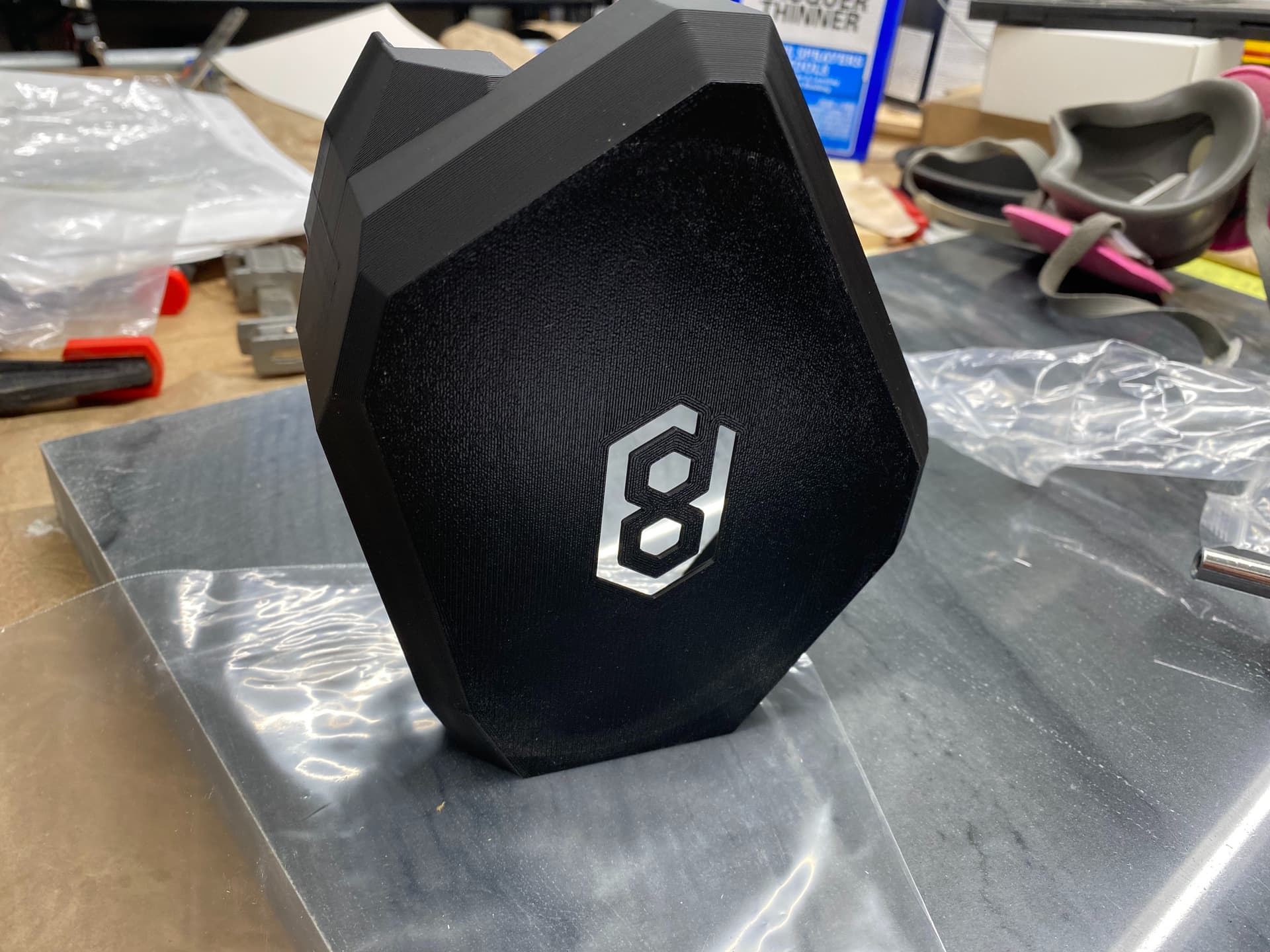
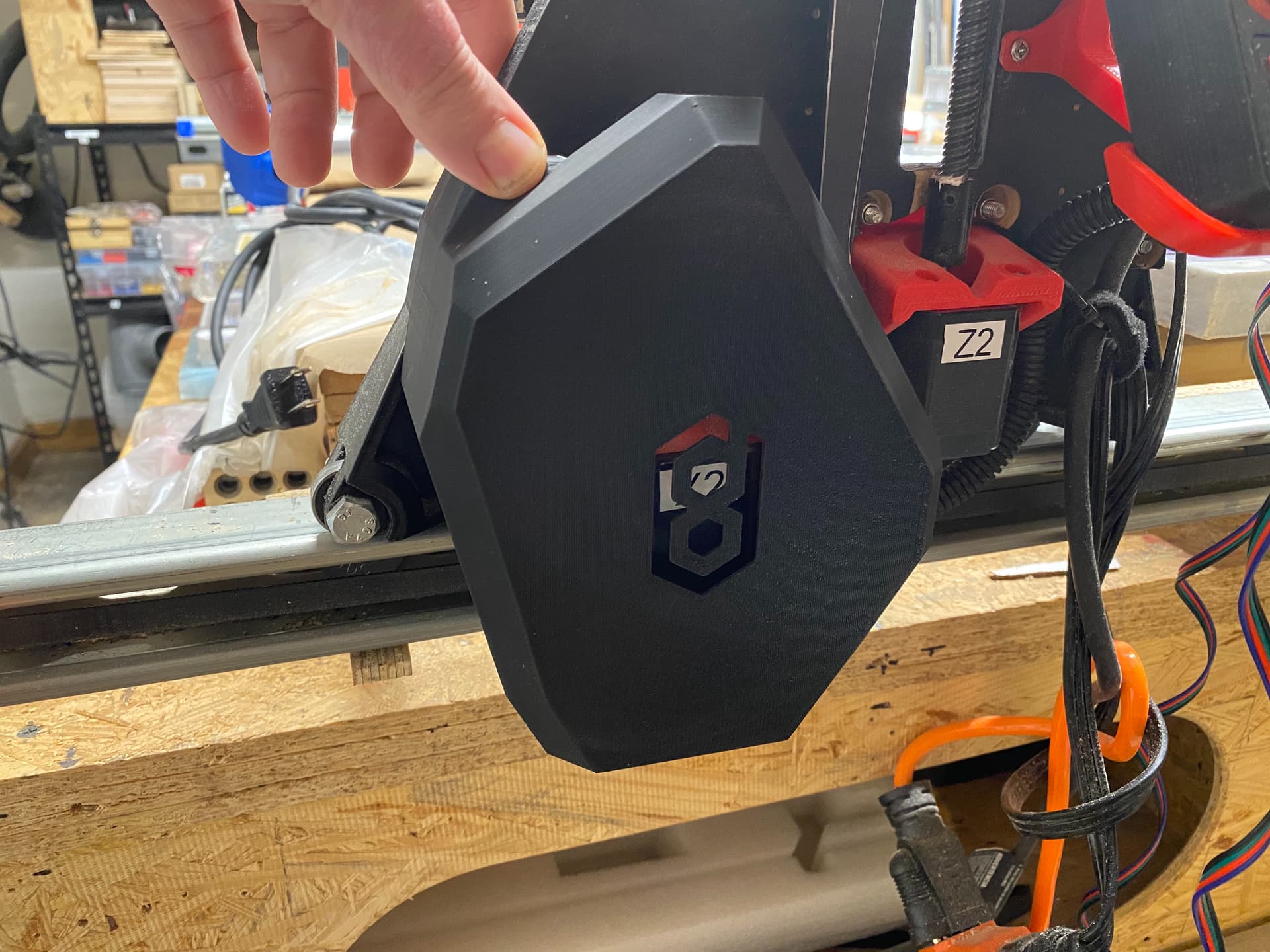
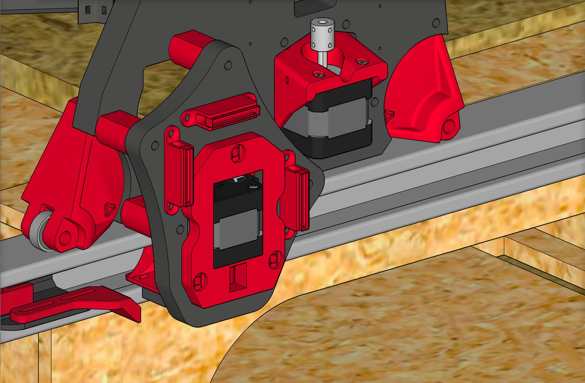
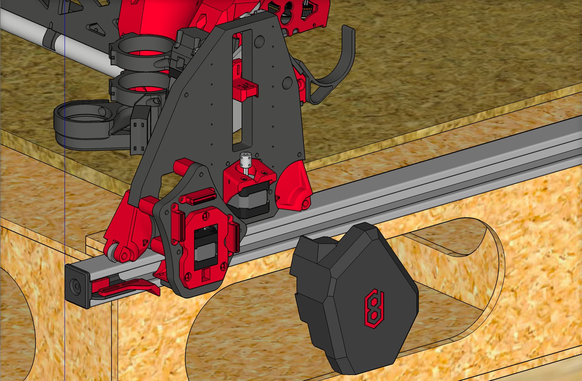
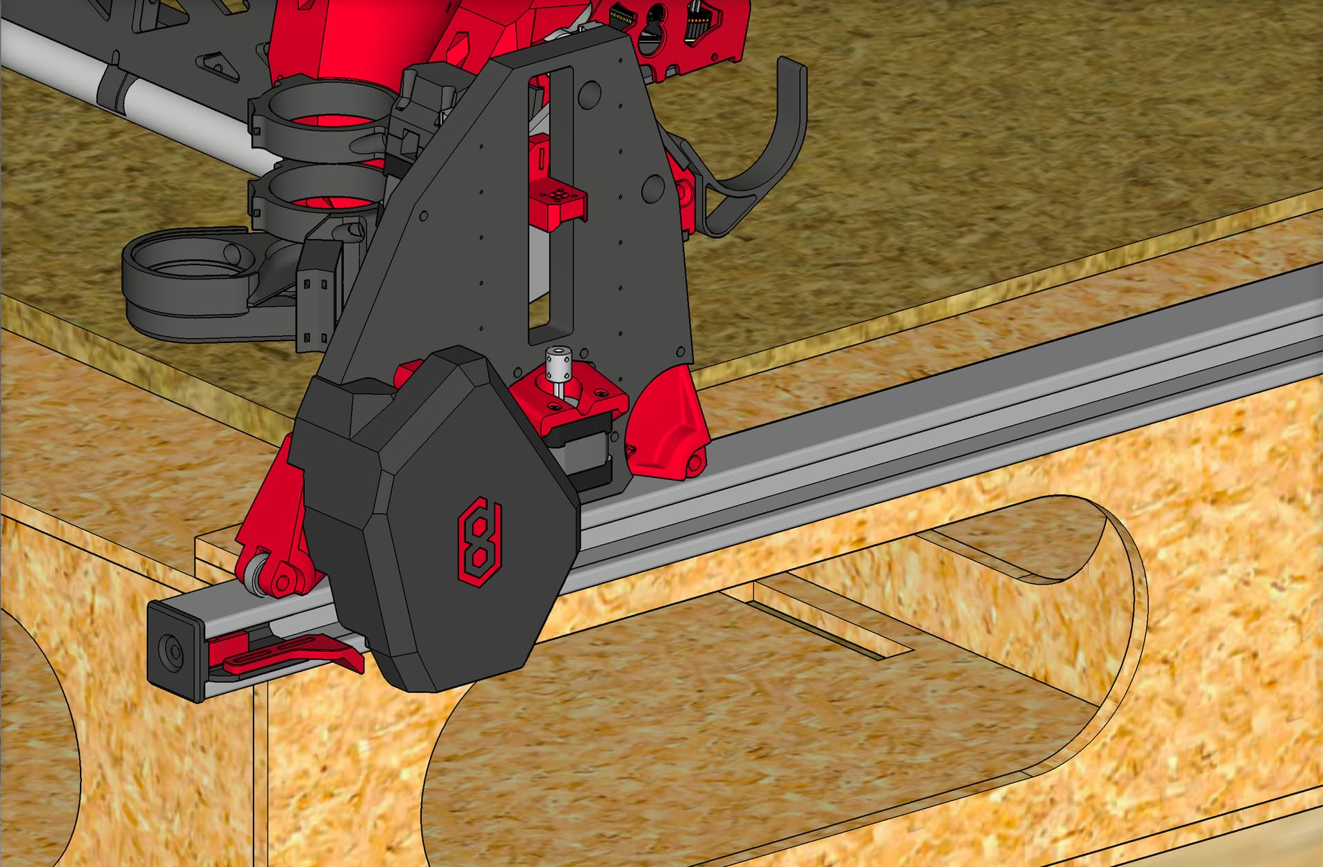
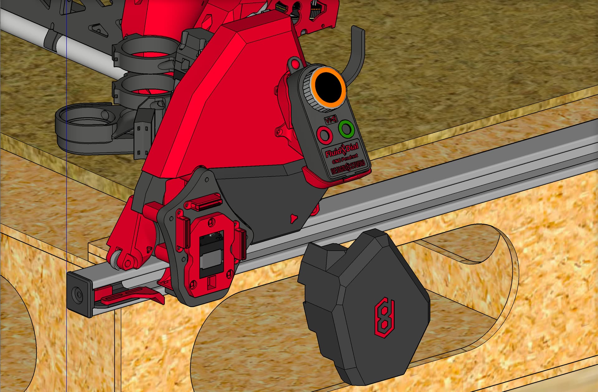
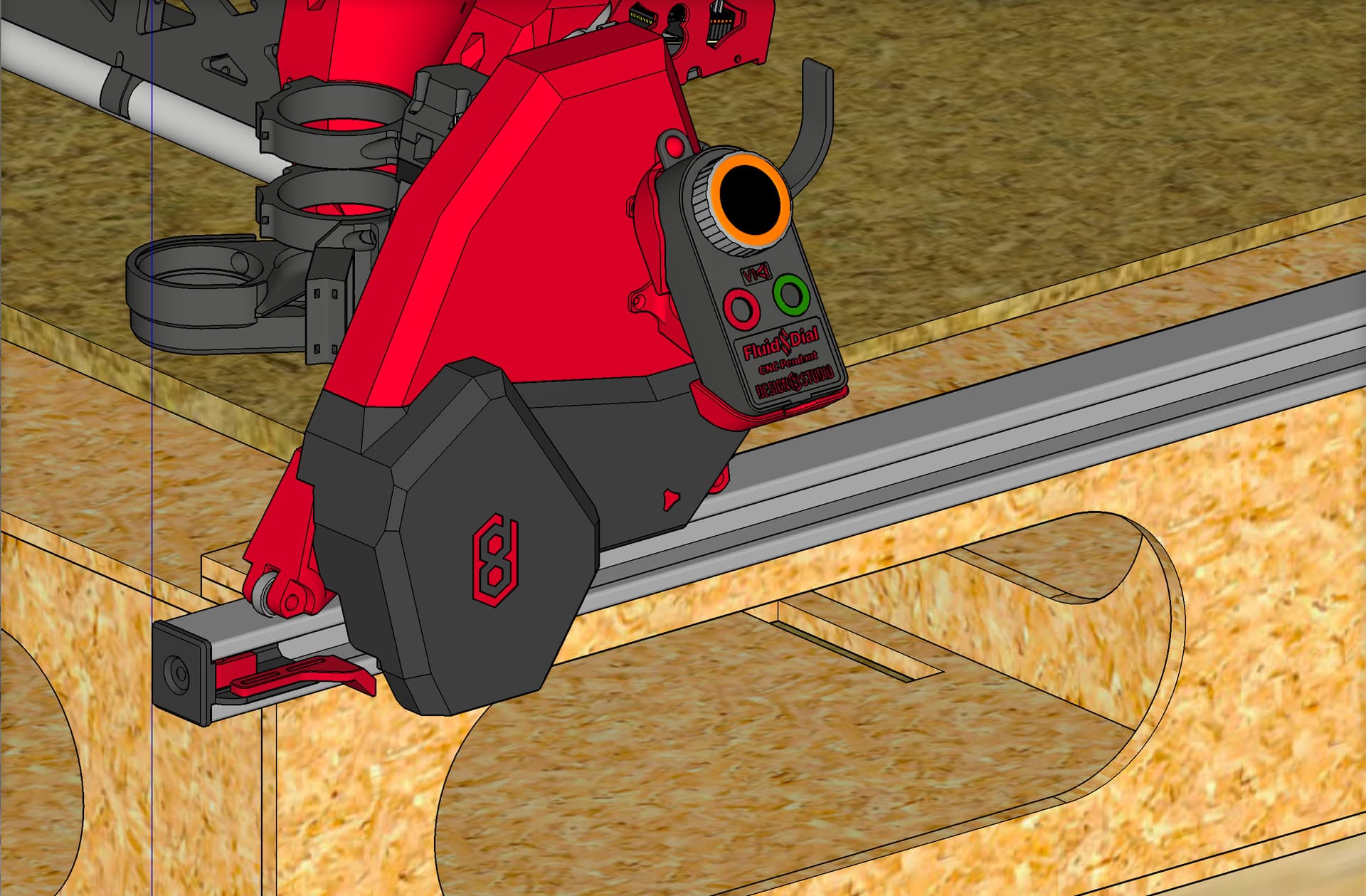
Spiral pendant holder.
1 Like
Wow, this is bonkers. You sir, are a madman. ![]()
![]() Appreciate it.
Appreciate it.
Now go for your star wars fenders! ![]()
3 Likes
12.5mm
I’m reserving the right to make extended Z plates in the future!
(This will never happen)
2 Likes
Doug that looks amazing - it really takes your machine to the next level!
Can you make your printer go faster please? I’m seriously anxious about this!
Ahh, I’m sorry about that. For those building the “standard” model, this should not be an issue at all.
This, I am sure is an example of the “hurrieder I go the slower I get”. Technically it’s not possible, because every part is a boolean subtract from the previous, but in this case I was really steaming and taking shortcuts and it looks as though I have overlooked a step. Have you repaired it or do you want me to make the correction?
If anyone has combined a standard height, with Doug’s rails - give us a shout and between us we’ll mash up that bottom cover with the stock “fenders”.
I repaired it on my end!
1 Like
Absolutely. one thing to note: the new add-on fender for the Y Extend plate, now does double duty in also filling in where the bottom fender used to cover the front. The bottom is now shorter, only coming over to meet the new add-on fender. The main front clip also got shortened by 25 mm.
All clips for both the left and right sides, including new mini clips for the add on fender for Y extend plate:

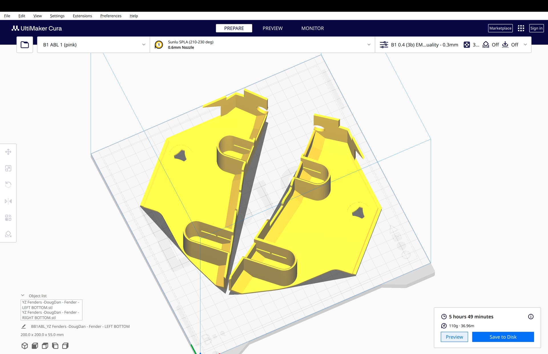
Both bottom fenders for both sides. Note they are shortened:
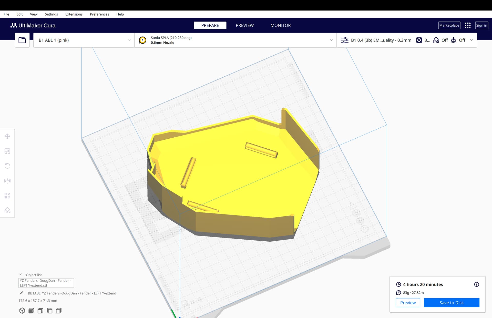
Left side, new add-on fender for Y extend plate:
Same, but no Design8Studio icon:
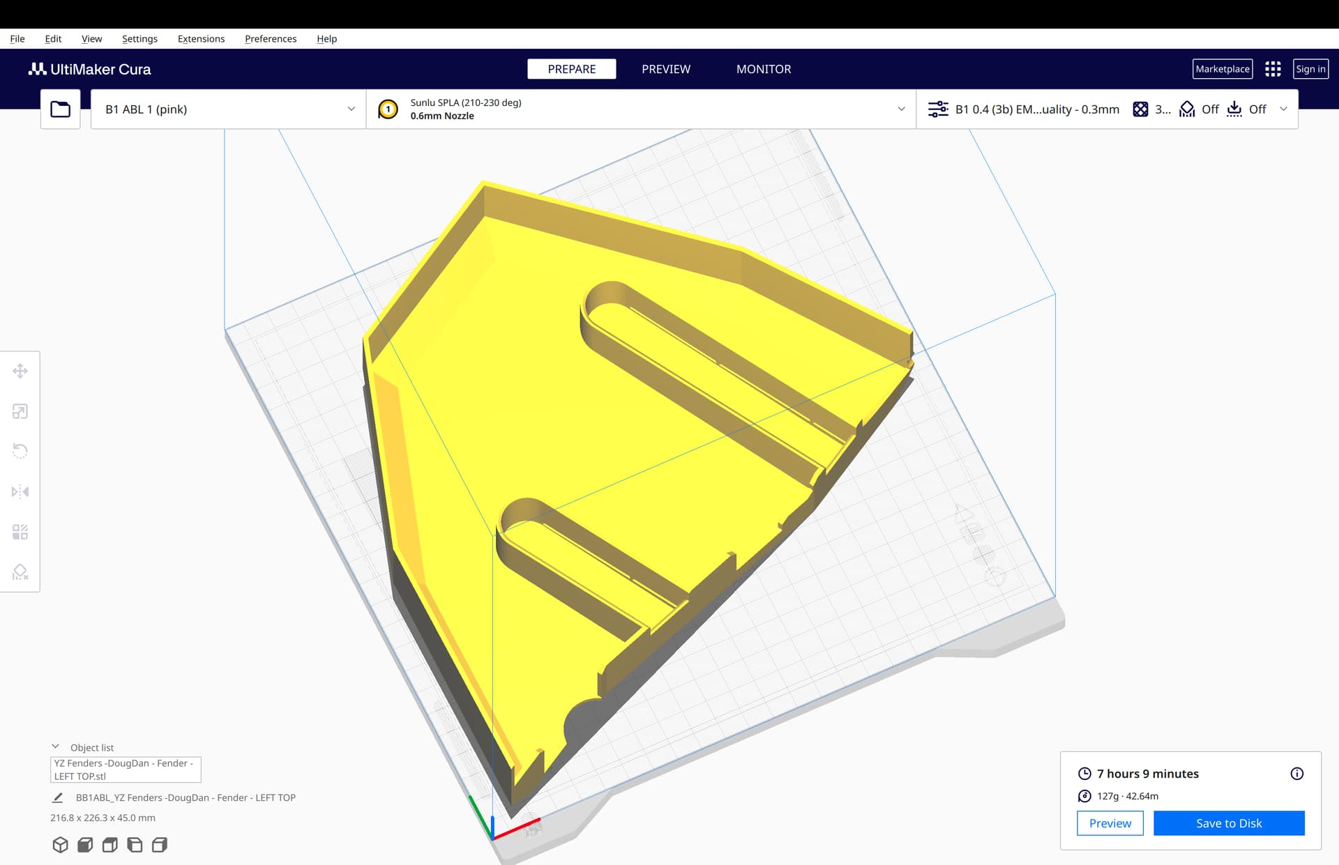
Left side, top fender:
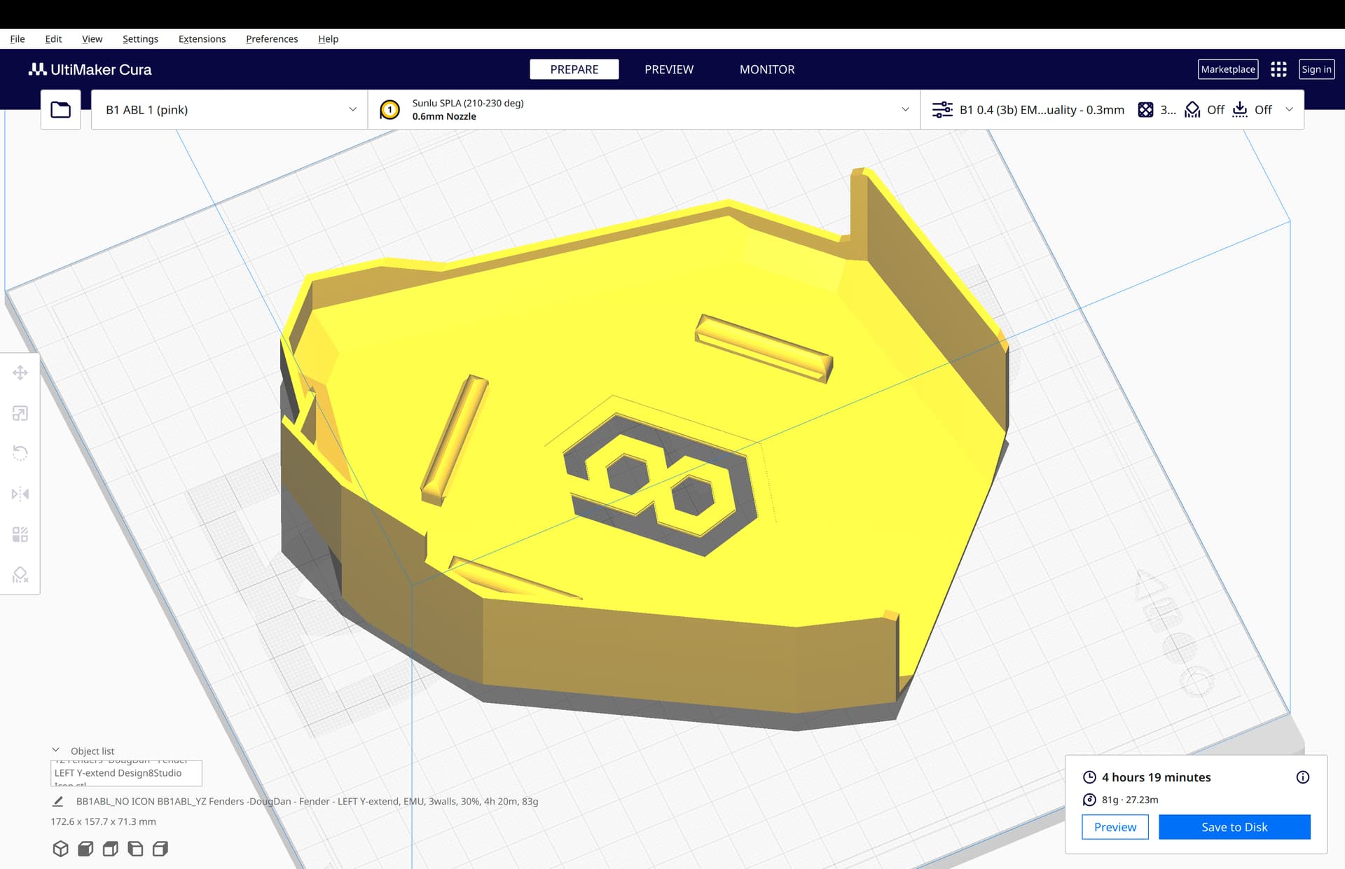
Right side, new add-on fender for Y extend plate:
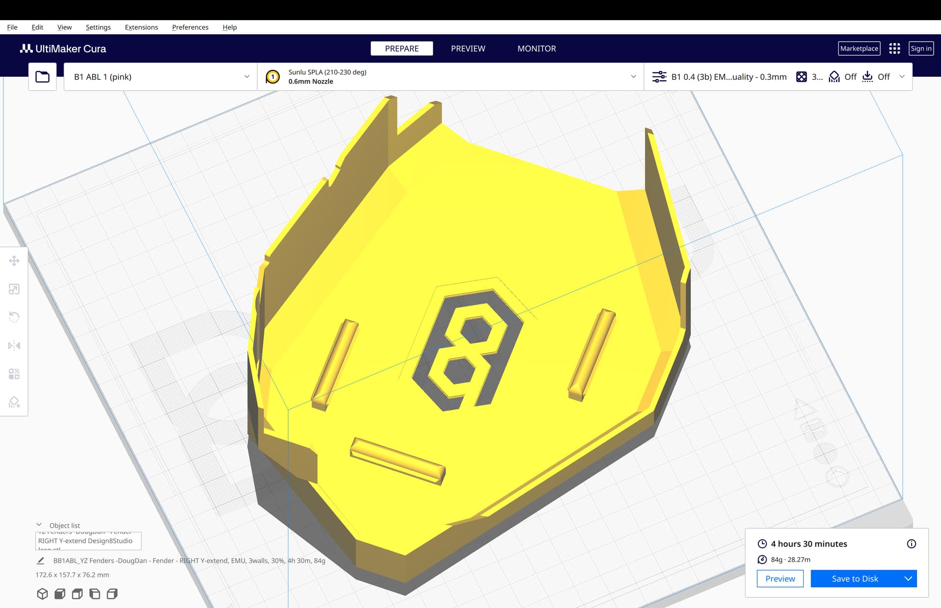
Same, but no Design8Studio icon:

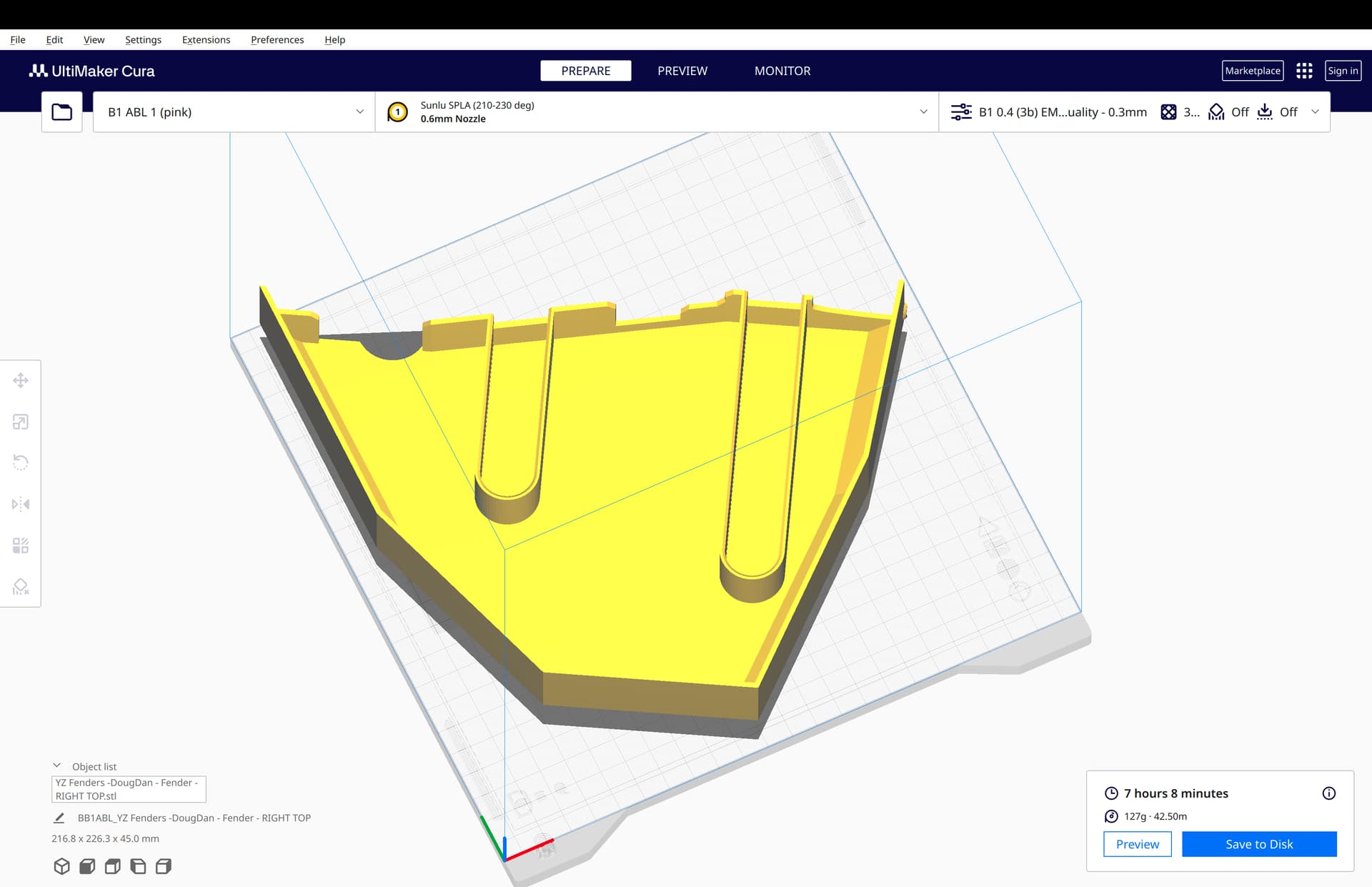
Right side, top fender:
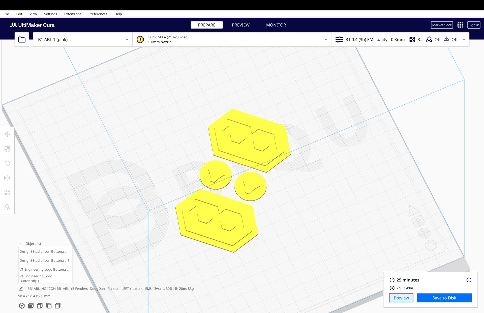
V1E and Design8Studio icon butons:
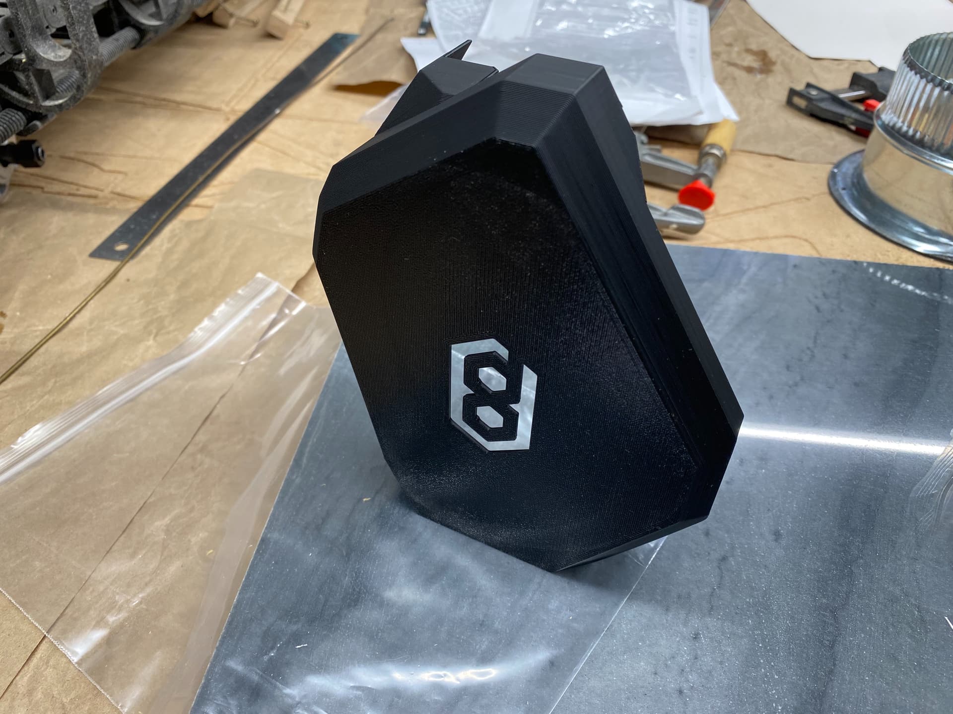
I’ve only gotton one part printed so far. I need to get the lead out and get a faster printer built!
I’m tackling the right side first. Here’s the one part I have printed. Fit seems good so far. Did realize one allowance needs opened up more. Will aim to save this part by making a cut to accomplish that, as well as modifying the source file.
Pics: Right side, add-on fender for Y-extend plate:
1 Like
Looks great.
1 Like
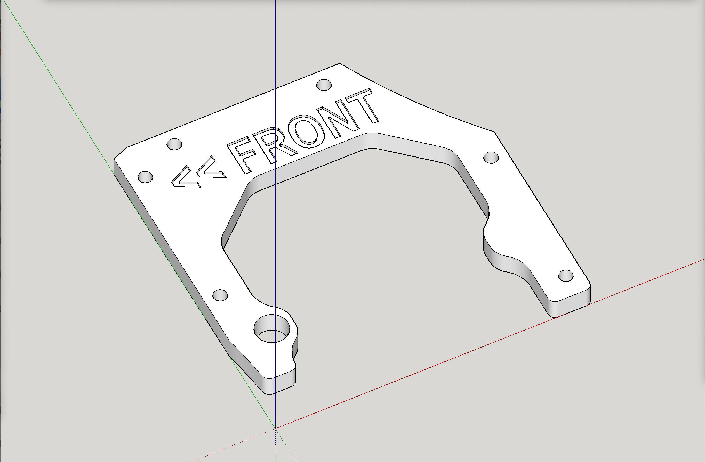
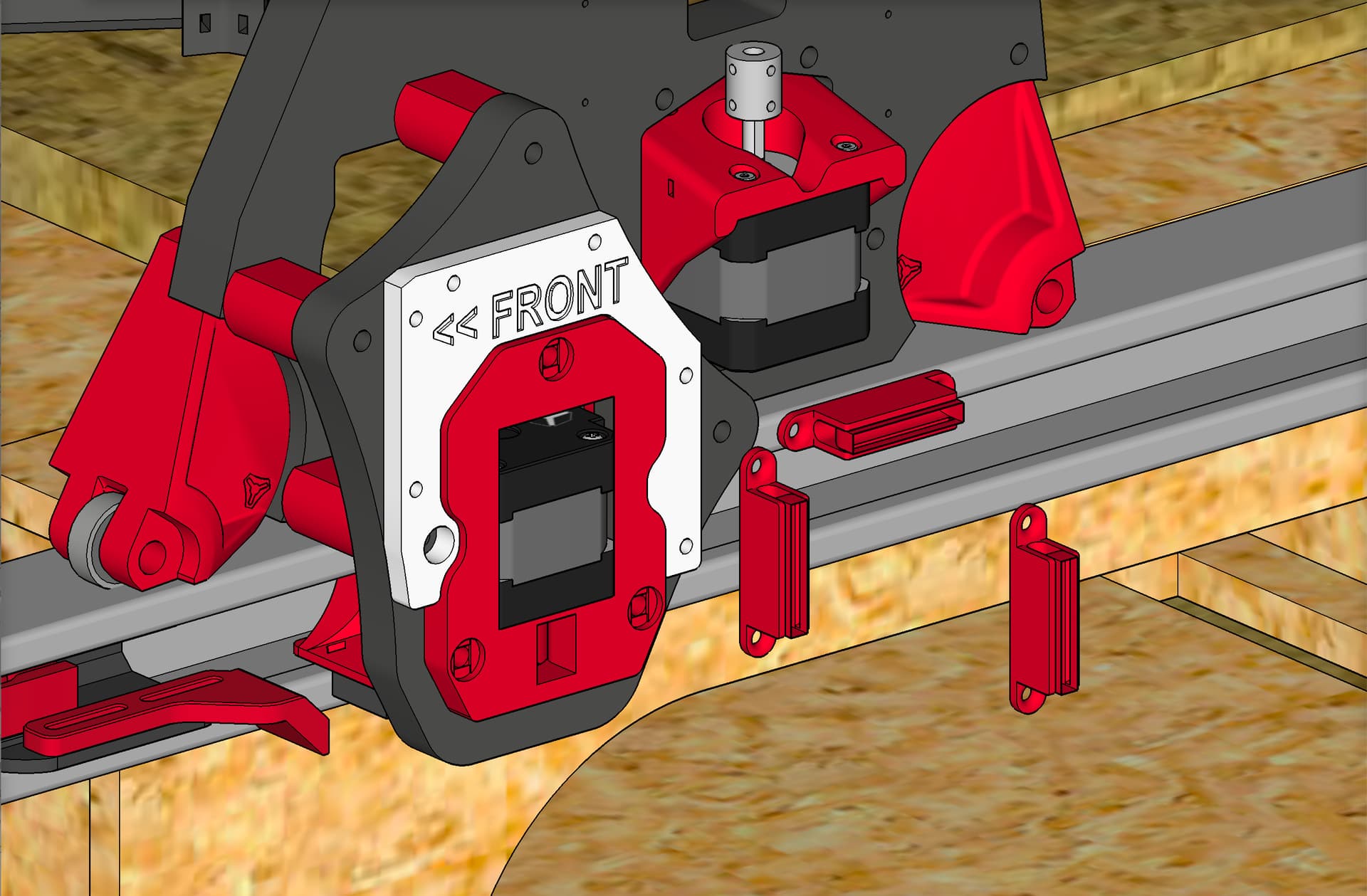
I whipped up this printable Pre-drilling Template for both Y-Extend Plates. Goal is to ensure the proper placement of the clips, with no muss or fuss.


I just snapped pics and recorded some video of me using the pre-drilling template, and installing the mini-clips and attaching the new add-on fender for Y-extend plate — and wow, both the template and the clips are working splendidly. I could not be more pleased.
1 Like
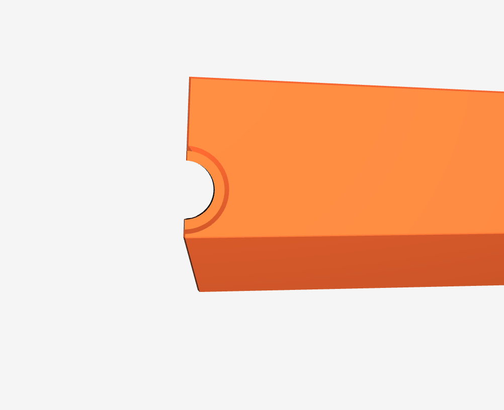
One idea to consider. If the round exit hole for wiring (at the back) was evenly split across the divide line between the top and bottom, it would probably print without supports. As it is, the hole on the bottom, has an overhang that requires supports.
Ahh, sorry Doug, that’s a once- off - it’s a function of your slightly different shape and I didn’t move it when I change it all - on the original that’s exactly what happens. It’s why in my assembly instructions I make a point of feeding the top and bottom panels onto the clips at once - if you don’t the wiring will get stuck one way or the other!
I can easily move it on your model if you don’t have that under control for now.
The other little discrepancies I knew about - that one is just a product of getting it to you without my usual check.
1 Like
Ah, that makes sense. You are the man!
How much width do they add onto the y axis?
There is no “stick out” so to speak that extends beyond the existing footprint of the LowRider. If this is not what you were asking about, please explain more.
1 Like
For all who are doing this, consider printing the clips in TPU or something with some flex to it. On my newly designed “mini clips” for the add-on fender for the Y-Extend plate for my Hidden Belts Mod, I printed them in PLA, and I was able to get 2 installs and 2 removals before the fins on the clips broke. On the big original clips, I printed in PLA, and I was able to get 1 install and the first removal showed broken fins on the clips.
hi doug are you going to post your stl on printables have the same
mod rail on my lr3
1 Like
Yes. I am assuming that Peter ( @bitingmidge ) is OK with that. It would be considered a remix for sure, even though some of it is original new work.
2 Likes
Since the flexing ability of the clips would be more robust if they were printed with the layer lines running the other way, I think will explore a way to print them standing up. For the big clips, it might mean printing them in sections that glued onto a base that’s been printed in the former orientation.
Speaking of which, to do the above trick, I would need a clip “base” and a clip “fins” for each mini clip, and for the long main original clips, each would need a “base” and probably 3 “fins” sections.
I am planning to make the Back Base bidirectional (can work for left or right side), as well as doing the same for the Front Base, and also, I plan to make the 3 “fins” sections for each to be all exactly alike, for ease of assembly. That would require adding the little openings present in one of the sections, to be present in all (and making sure they are dimensioned to work in either direction). Also, since the back clip has one section that is sloped so that it’s about 0.9 or so shorter on one end, I would need to make the whole thing shorter by that amount, so everything becomes uniform and bidirectional. This would mean the Back Base has no right or left constraint, and no top/bottom constraint, and similarly the “Fins” that get glued to it have no such constraints. Same would go for the front set of base and fins. All parts can go anywhere, left, right, top, center, bottom… all uniform.
Since the original has clips of equal length, it may conceivably be possible for the original to have even more uniformity, with any clip being able to serve front, back, left, or right.
UPDATE: I think I’ve sussed out a way to make 3 “fin” parts that can work universally in either the top, middle, or bottom positions, and regardless of which way they are rotated before being glued in place on the base. It does mean that all the screw holes need to be the same size (the 2 added screw holes for attaching to MDF or plywood were larger, and I’m reducing them to match the others). It also means all the holes either have, or don’t have, the nut capture slots. I’m currently doing it both with and without them. Note: the approach has, on the universal fin parts, more holes than any one needs, so there are holes where needed. The specific needed holes are on the base, so on the fin parts, the needed holes “go through” the base, and the unneeded ones don’t. Because that seemed like it might be complicated to explain, I also came up with an alternative that has two “outer” fin prints and one “middle” fin print, and each only has needed holes. ![]()
6mm (1/4") on both sides.
I think I’ve broken and printed clips in every way possible!
The best solution for me was to print them with five perimeters - this makes the transition to the curve almost solid - I am curious to see if TPU would work.
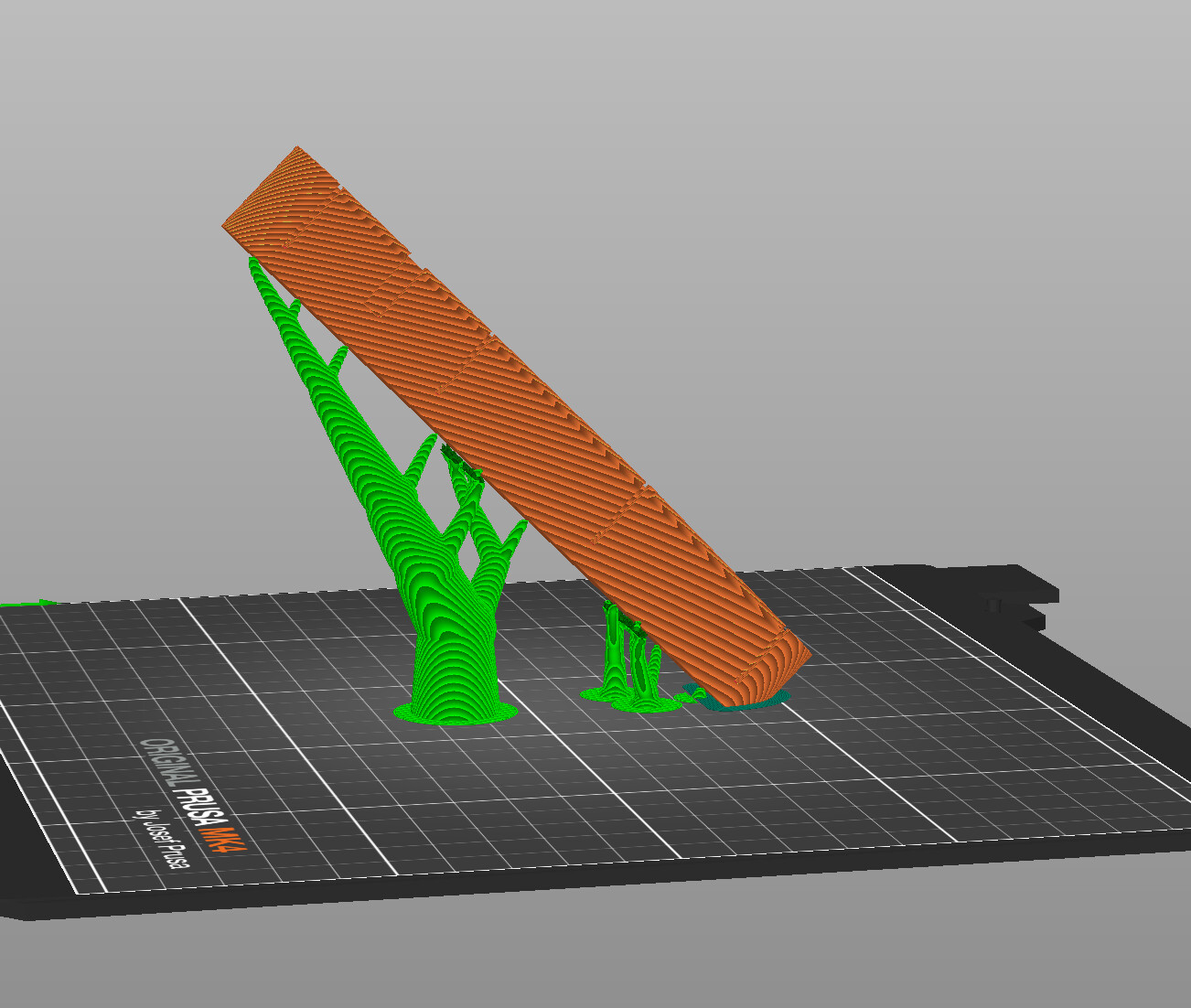
Rather than printing them vertical, I think 45° to horizontal is a much better solution. I think that will give a much better print than vertically without supports or messing around with mulitple parts. Your’s are a little more problematic than the standard version because they are shorter due to the width of your plates.
Once you have them printed and installed they are fine - I haven’t broken a clip in place, but I’ve snapped quite a few with clumsy fingers doing up screws.
I’ve set it up to use organic supports as a test, but can easily incorporate a break-away fin to speed printing up.
1 Like